Transcription
International Journal of Engineering Research & Technology (IJERT)ISSN: 2278-0181Vol. 2 Issue 11, November - 2013FSM & Handshaking Based AHB to APB Bridge for High SpeedSystemsProf. Ravi Mohan Sairam1 Prof. Sumit Sharma2 Miss. Geeta Pal31Head of the Department (M.Tech)Shri Ram Institute of Technology, Jabalpur 482002 (M.P) India2Head of the Department (Electronics & Communication)Shri Ram Institute of Technology, Jabalpur 482002 (M.P) India3Master of Engineering IV Semester (VLSI)Shri Ram Institute of Technology, Jabalpur 482002 (M.P) India1 IntroductionIntegrated circuits have entered the era of System-ona-Chip (SoC), which refers to integrating allcomponents of a computer or other electronic systeminto a single chip. It may contain digital, analog,mixed-signal, and often radio-frequency functions –all on a single chip substrate. With the increasingdesign size, IP is an inevitable choice for SoC design.And the widespread use of all kinds of IPs haschanged the nature of the design flow, making OnChip Buses (OCB) essential to the design. Of allOCBs existing in the market, the AMBA bus systemis widely used as the de facto standard SoC bus.ARM announced availability of the AMBA 4.0specifications. As the de facto standard SoC bus,AMBA bus is widely used in the high-performanceSoC designs. The AMBA specification defines an onchipCommunication standard for designing highperformance embedded microcontrollers. The AMBA4.0 specification defines five buses/interfaces.IJERTAbstractMicroprocessor performance has improvedrapidly these years. In contrast memorylatencies and bandwidths have improvedlittle by using advanced microcontroller busarchitecture with its advanced highperformancebus.TheAdvancedMicrocontroller Bus Architecture (AMBA) isa widely used interconnection standard forSystem on Chip (SoC) design. In order tosupport high-speed pipelined data transfers,AMBA supports a rich set of bus signals,making the analysis of AMBA-basedembeddedsystemsachallengingproposition. The goal of this work is tosynthesize and simulate complex interfacebridge between Advanced High performanceBus (AHB) and Advanced Peripheral Bus(APB) known as AHB2APB Bridge. Toachieve high performance proposedarchitecture is FSM based pipelined APBto-AHP Bridge and Vice-versa. This alsoinvolves the Back notation for Synthesized ofBridge module and to perform Functionaland Timing Simulation using Xilinx ISE.IJERTV2IS110601 Advanced extensible Interface (AXI)Advanced High-performance Bus (AHB)Advanced System Bus (ASB)Advanced Peripheral Bus (APB)Advanced Trace Bus (ATB)AXI, the next generation of AMBA interface definedin the AMBA 4.0 specification, is targeted at highperformance; high clock frequency system designsand includes features which make it very suitable forhigh speed sub-micrometer interconnection.www.ijert.org2799
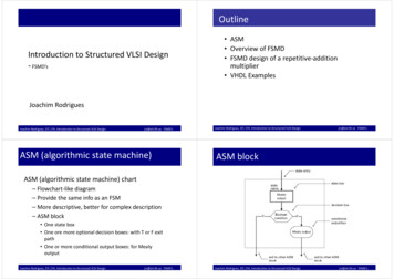
International Journal of Engineering Research & Technology (IJERT)ISSN: 2278-0181Vol. 2 Issue 11, November - 20131. Low power2. Latched address and control3. Simple interface4. Suitable for many peripheralsThese changes to the APB also make it simpler tointerface it to the new Advanced High-performanceBus (AHB).IV. OPERATION OF AHB2APB BRIDGEThe AHB2APB interfaces AHB and APB. It buffersaddress, controls and data from the AHB, drives theAPB peripherals and return data along with responsesignal to the AHB. The AHB2APB interface isdesigned to operate when AHB and APB clocks havethe any combination of frequency and phase[8].TheAHB2APB performs transfer of data fromAHB to APB for write cycle and APB to AHB forRead cycleA. Features of AHB2APB BridgeInterface between AMBA high performance(AHB) and AMBA peripheral bus (APB)provides latching of address, controls andsignals for APB peripherals. Supports forfollowingAPB compliant slaves and peripherals.Peripherals which require additional wait states.Figure 2. Pin details of AHB2APB Bridgebus[2],datatheIJERTAdvanced high-performance bus (AHB)AHB is a new generation of AMBA bus, which isintended to address the requirements of highperformance synthesizable designs. It is a highperformance system bus that supports multiple busmasters and provides high-bandwidth operation.AMBA AHB [6] implements the features required forhigh-performance, high clock frequency systemsincluding:1. High performance2. Pipelined operation3. Multiple bus masters4. Burst transfers5. Single-cycle bus master handover6. Non-tri state implementation7. Wider data bus configurations (64/128bits).Bridging between this higher level of bus and thecurrent ASB/APB can be done efficiently to ensurethat any existing designs can be easily integrated. AnAMBA AHB design may contain one or more busmasters typically a system would contain at least theprocessor and test interface. However, it would alsobe common for a Direct Memory Access (DMA) orDigital Signal Processor (DSP) to be included as busmasters. The external memory interface, APB Bridgeand any internal memory are the most common AHBslaves. Any other peripheral in the system could alsobe included as an AHB slave. However, lowbandwidth peripherals typically reside on the APB.B. Advanced System Bus (ASB)The AMBA ASB is for high-performance modules. Itis an alternative system bus suitable for use wherehigh-performances features of AHB are notrequired.ASB also supports the efficient connectionof processors, on-chip memories and off-chipexternal memory interfaces with low-powerperipheral macro cell functions.1. Features of ASB:2. Burst transfers3. Pipelined transfer operation4. Multiple bus masters.5. Advanced peripheral bus (APB)The Advanced Peripheral Bus (APB) is part of theAdvancedMicrocontrollerBusArchitecture(AMBA) hierarchy [7] of buses and is optimized forminimal power consumption and reduced interfacecomplexity. The AMBA APB should be used tointerface to any peripherals which are low-bandwidthand do not require the high performance of apipelined bus interface. The latest revision of theAPB ensures that all signal transitions are onlyrelated to the rising edge of the clock.This improvement means the APB peripherals can beintegrated easily into any design flow.Features of APB:IJERTV2IS110601B. AHB ResponseThe sub-module AHB Response sequences the waythat the AHB2APB responds to AHB requests. Validcommands are forwarded to control transfer foraction. Invalid commands are not forwarded and anerror message is generated. It operates on AHBCLOCK and RESET. The control Transfers block inFig. 3 transfers AHB control signal to the APBaccess with appropriate delays inserted to map thepipelined AHB protocol to the two cycle APBprotocol. It ensures that only one request is presentedto the APB access while it is processing a request. Itoperates on AHB CLOCK and RESET.APB BusThe APB access generates the control signals on theAPB for read and writes cycles. It operates on APBCLOCK and RESET. The APB Bridge is the onlybus master on the AMBA APB. In addition, the APBBridge is also a slave on the higher-level system bus.The bridge unit converts system bus transfers intoAPB transfers and performs the following functions:Latches the address and holds it valid throughout thetransfer.Decodes the address and generates a peripheral select(PSEL). Only one select signal can be active during atransfer.Drives the data onto the APB for a write transfer.www.ijert.org2800
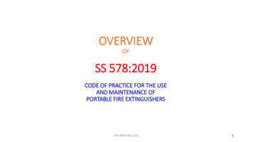
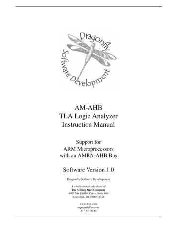
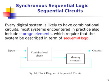
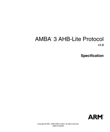
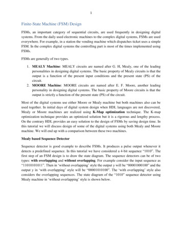
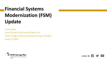
International Journal of Engineering Research & Technology (IJERT)ISSN: 2278-0181Vol. 2 Issue 11, November - 2013Drives the APB data onto the system bus for a readtransfer.1.2 AXI HANDSHAKE MECHANISMAPB4 SLAVE 0AXI4 MASTERAXI4-LITE T0 APBBRIDGEIn AXI 4.0 specification, each channelhREADY signals for handshaking. The sour whenthe control information or data destination assertsREADY when it can a information or data. Transferoccurs only VALID and READY is asserted. Casesof VALID/READ handshaking. Note asserts VALID,the corresponding control in must also be available atthe same time. Indicate when the transfer occurs. Atransfer the positive edge of clock. Therefore, theregister input to sample the READY signal.APB4 SLAVE 1APB SLAVE 15Figure1-Block Diagram1.1 SIGNAL CONNECTIONThe bridge uses:AMBA AXI-Lite signals as described in the AMBA.AXI-Lite 4.0 protocol specification.AMBA APB signals as described in the AMBA APB.4.0 protocol specification.IJERTV2IS110601The APB bridge buffer addres,,control and datafrom AXI4-lite ,and drives the APB peripherals andreturns data and response signal to the AXI4-lite.itdecodes the address using an internal address map toselect the peripherals.the bridge is designed tooprerate when the APB and AXI4-lite haveindependent clock frequency and phase.for everyAXI channel, invalid commonds are not forwardedand an error response generated.thay is once andperipheral acess does not exists ,the APB bridge willgenerate DECERR as response through the responsechannel.(read or write).and if the target peripheralexists,but asserts PSLVERR, it will give a SLVERRresponse.IJERT Generates a timing strobe, PENABLE, for thetransfer.Figure 2 - Signal Connectionwww.ijert.org2801
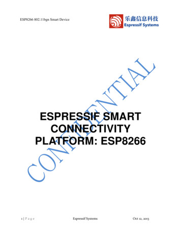
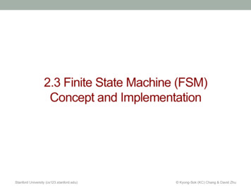
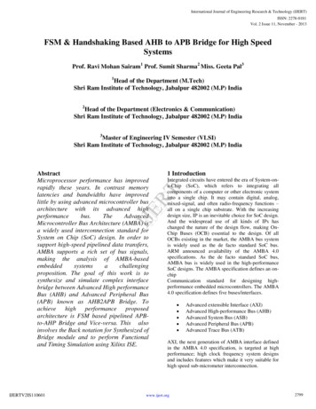
International Journal of Engineering Research & Technology (IJERT)ISSN: 2278-0181Vol. 2 Issue 11, November - 2013clock and synchronous clock and the asynchronousrespectively.ec2 thBTMTBF c1 fclk fdata2.2SYNCRONISERDesigners can use special metastable hardened flopsfor increasing the MTBF. Synchronizer flop is usedfollowing the signal DB. So, instead of themetastable signal DB being used in the functiondownstream. the stable signal DB2 is used in thelogic downstream[8]. In the AXI4-Lite to APBbridge, we use synchronizer block designs forcommunicate between the AXI and APB clockdomain.IJERT3. FINITE STATE MACHINEA finite state machine is a mathematical abstractionsometimes used to design digital logic or computerprograms.It is a behavior model composed of a finitenumber of states, transitions between those states,and actions, similar to a flow graph in which one caninspect the way logic runs when certain conditionsare met. The state transition diagram is a picture ofour state machine model. Figure. 5 is the statetransition diagram of our FSM.The state machine operates through the followingstates:IDLE. This is the default state of the FSM. SETUP.When a write transfer request is asserted, the FSMmoves into the SETUP state.SETUP. When a read transfer request is asserted, theFSM moves into the SETUP state.ENABLE. The enable signal, PENABLE, is assertedin the ENABLE state. READ ACCESS. The enablesignal, PENABLE, is asserted in the ENABLE state.HRESP. When the AXI read data channel is notready for receiving signal RRESP, then stay inHRESP state. States HRESP and ENABLE areadded, because the APB is not pipelined, wait statesare added during transfers between the APB and AXIinterface states HRESP and ENABLE are added,because the APB is not pipelined, wait states areadded during transfers between the APB and AXIinterface. System Verilog source code sample of theenumerated type encoded FSM is given below.Figure 3-Handshake Mechanism 2 .CLOCK DOMAIN CROSSINGA clock domain crossing (Cis) when a signal crossesfrom one clock to another. If a signal does not assertlong may appear asynchronous on Metastabilityhappens when setup/hold time window. Sync into ahigher clocked domain registering the signal througha source domain, thus holding detected by the higherSynchronizing a signal travers in more cumbersome.This typical clock domain with a form of domain tothe source domain, detected.2.1 METASTABILITYMetastability cannot be another metastable signalenabled sign. The metastability ousting the meantime between mtbf Where C1 and C2 are constantused to build the flip-flop metastable output, andIJERTV2IS110601 www.ijert.org2802
International Journal of Engineering Research & Technology (IJERT)ISSN: 2278-0181Vol. 2 Issue 11, November - 2013various read and write transfers It shows that whenboth read and write requests are active, read is givenmore priority.Before Static Timing Analysis (STA), it is necessaryto inform the EDA tools that ACLK and PCLK aretwo asynchronous clock domains:Figure 6 Typical Read and Write TransferArea ReportNumberofSlicesNumber of SliceFlip FlopsNumber of 4input LUTsNumber of IOsNumberofbonded IOBsIOB Flip FlopsNumberofGCLKs5out of7680%3out of15360%10out of15360%111110out of14078%181out of425%Timing reportMinimum periodIJERTMinimum input arrival timebefore clockMaximum output requiredtime after clockMaximumcombinationalpath delayFigure 5-FSM State Diagram5.928ns(MaximumFrequency: 168.691MHz)6.943ns10.702ns10.134nsAccording AXI specification, the read the readaddress channel, write address channel and write datachannel are completely independent. Each channelhas a set of forward signals and a feedback signal forhandshaking. A read and a write requests may beissued simultaneously AWVALID/WVALID andARVALID are asserted high simultaneously) fromAXI4-Lite, the AXI4-Lite to APB bridge will givemore priority to the read request than to the writerequest. That is, when both write and read requestsare valid, the write request is initiated on APB afterthe read is requested on APB4 SIMULATIONS AND IMPLEMENTATIONThe timing diagram shown in Figure below.illustrates theAXI4-Lite to APB bridge operation forIJERTV2IS110601www.ijert.org2803
International Journal of Engineering Research & Technology (IJERT)ISSN: 2278-0181Vol. 2 Issue 11, November - 2013IJERT5. CONCLUSIONIn this study, we provide an implementation of AXI4Lite to APB bridge which has the following features:1. 32-bit AXI slave and APB master interfaces.2. PCLK clock domain completely independent ofACLK clock domain.3. Support up to 16 APB peripherals.4. Support the PREADY signal which translates towait states on AXI.5. An error on any transfer results in SLVERR asthe AXI read/write response.6. REFERENCES[1] ARM,"AMBA Protocol Specification 4.0",www.arm.com, 2010.[2]Ying-ZeLiao,"SystemDesignandImplementation of AXI Bus", National Chiao TungUniversity, October 2007.[3] Clifford E. Cummings, "Coding And ScriptingTechniques For FSM Designs With SynthesisOptimized, Glitch-Free Outputs," SNUG (SynopsysUsers Group Boston, MA 2000) Proceedings,September 2000.IJERTV2IS110601[4] Clifford E. Cummings, “Synthesis and ScriptingTechniques for Designing Multi-AsynchronousClock Designs,” SNUG 2001[5] Chris Spear, "SystemVerilog for Verification, 2 ndEdition"Springer,www.springeronline.com, 2008.[6] Lahir, K., Raghunathan A., Lakshminarayana G.,“LOTTERYBUS:anewhigh-performancecommunication architecture for system-on-chipdeisgns,” in Proceedings of Design AutomationConference, 2001.[7] Sanghun Lee, Chanho Lee, Hyuk-Jae Lee, “Anew multi-channel onchip-bus architecture forsystem-on-chips,” in Proceedings of IEEEinternational SOC Conference, September 2004.[8] Martino Ruggiero, Rederico Angiolini, FrancescoPoletti, Davide Bertozzi, Luca 86[9] Benini, Roberto Zafalon, “Scalability Analysis m on System-on-Chip, 2004. Lukai Cai,Daniel Gajski, “Transaction level modeling: anoverview,” in Proceedings of the 1st IEEE/ACM/IFIPinternational conference onHardware/software codesign and system synthesis,October 2003.[10] Min-Chi Tsai, “Smart Memory ControllerDesign for Video Applications,” Master thesis:National Chiao Tung University, July 2006.www.ijert.org2804
downstream. the stable signal DB2 is used in the logic downstream[8]. In the AXI4-Lite to APB bridge, we use synchronizer block designs for communicate between the AXI and APB clock domain. 3. FINITE STATE MACHINE A finite state machine is a mathematical abstraction sometimes used to design digital logic or computer