Transcription
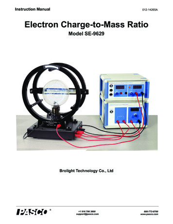
Instruction Manual012-14265AElectron Charge-to-Mass RatioModel SE-9629Brolight Technology Co., Ltd
Table of ContentsEquipment List - - - - - - - - - - - - - - - - - - - - - - - - - - - - - - - - - - - - - - - - - - - - - - - - - - - - 1Limited Warranty and Limitation of Liability - - - - - - - - - - - - - - - - - - - - - - - - - - - - - - - - 2Safety Information - - - - - - - - - - - - - - - - - - - - - - - - - - - - - - - - - - - - - - - - - - - - - - - - - 2Introduction - - - - - - - - - - - - - - - - - - - - - - - - - - - - - - - - - - - - - - - - - - - - - - - - - - - - - - 3Background Information - - - - - - - - - - - - - - - - - - - - - - - - - - - - - - - - - - - - - - - - - - - - - 4Principle of the Experiment - - - - - - - - - - - - - - - - - - - - - - - - - - - - - - - - - - - - - - - - - - - 4Installation and Maintenance - - - - - - - - - - - - - - - - - - - - - - - - - - - - - - - - - - - - - - - - - - 4Experiment Procedure - - - - - - - - - - - - - - - - - - - - - - - - - - - - - - - - - - - - - - - - - - - - - 10Appendix A: General Specifications - - - - - - - - - - - - - - - - - - - - - - - - - - - - - - - - - - - - 13Appendix B: Teacher’s Notes - - - - - - - - - - - - - - - - - - - - - - - - - - - - - - - - - - - - - - - - 14Appendix C: Technical Support - - - - - - - - - - - - - - - - - - - - - - - - - - - - - - - - - - - - - - - 15Appendix D: Product End of Life Disposal Instructions - - - - - - - - - - - - - - - - - - - - - - - 15 ii
Instruction Manual012-14265AElectron Charge-to-Mass RatioSE-96292.1.4.3.5.7.6.Equipment ListIncluded EquipmentModelElectron Charge-to-Mass RatioSE-962911.e/m TubeSE-965112.Helmholtz Coils and BaseSE-962623.Mirrored ScaleQuantity14. Tunable DC (Constant Voltage) Power Supply II, 12 V / 100 V / 200 VSE-964415. Tunable DC (Constant Current) Power Supply, 3.5 A / 6.3 VSE-962216. Connecting cable, 850 mm, redEM-9740Set of 57. Connecting cable, 850 mm, blackEM-9745Set of 5Connecting Cable for PASCO 850 Universal Interface (not shown)UI-52182Power Cord (not shown)2012-14265A1
SE-9629Electron Charge - t o- M ass R at ioRecommended Equipment for Alternate Data Recording MethodModel850 Universal InterfaceUI-50001PASCO Capstone SoftwareUI-54001High Current SensorPS-21931QuantityLimited Warranty and Limitation of LiabilityThis Brolight product is free from defects in material and workmanship for one year from the date of purchase. This warrantydoes not cover fuses, or damage from accident, neglect, misuse, alteration, contamination, or abnormal conditions of operationor handling. Resellers are not authorized to extend any other warranty on Brolight’s behalf. To obtain service during the warranty period, return the unit to point of purchase with a description of the problem. THIS WARRANTY IS YOUR ONLYREMEDY. NO OTHER WARRANTIES, SUCH AS FITNESS FOR A PARTICULAR PURPOSE, ARE EXPRESSED ORIMPLIED.BROLIGHT IS NOT LIABLE FOR ANY SPECIAL, INDIRECT, INCIDENTAL OR CONSEQUENTIAL DAMAGES OR LOSSES, ARISING FROM ANY CAUSE OR THEORY. Since some states or countries do not allow the exclusionor limitation of an implied warranty or of incidental or consequential damages, this limitation of liability may not apply to you.Safety InformationWARNING: To avoid possible electric shock or personal history, follow these guidelines. 2Clean the equipment only with a soft, dry cloth.Before use, verify that the apparatus is not damaged.Do not defeat the power cord safety ground feature.Plug into a grounded (earthed) outlet.Do not use the product in any manner that is not specified by the manufacturer.Do not install substitute parts or perform any unauthorized modification to the product.Line and Current Protection Fuses: For continued protection against fire, replace the line fuse andthe current-protection fuse only with fuses of the specified type and rating.Main Power and Test Input Disconnect: Unplug instrument from wall outlet, remove power cord,and remove all probes from all terminals before servicing. Only qualified, service-trainedpersonnel should remove the cover from the instrument.Do not use the equipment if it is damaged. Before you use the equipment, inspect the case. Payparticular attention to the insulation surrounding the connectors.Do not use the equipment if it operates abnormally. Protection may be impaired.When in doubt,have the equipment serviced.Do not operate the equipment where explosive gas, vapor, or dust is present. Don't use it underwet conditions.Do not apply more than the rated voltage, as marked on the apparatus, between terminals orbetween any terminal and earth ground.When servicing the equipment, use only specified replacement parts.012-14265A
Electron Ch arg e-to-Mass R a ti oEl e c t ri c a l S y m b o l s Use caution when working with voltages above 30 V AC rms, 42 V peak, or 60 V DC. Suchvoltages pose a shock hazard. To avoid electric shock, do not touch any bare conductor with hand or skin. Adhere to local and national safety codes. Individual protective equipment must be used toprevent shock and arc blast injury where hazardous live conductors are exposed. Special note: If a dangerous voltage is applied to an input terminal, then the same voltage mayoccur at all other terminals.Electrical SymbolsAlternating CurrentDirect CurrentCaution, risk of danger, refer to the operating manualbefore use.Caution, possibility of electric shockEarth (ground) TerminalProtective Conductor TerminalChassis GroundConforms to European Union directives.WEEE, waste electric and electronic equipmentFuseOn (Power)Off (Power)In position of a bi-stable push controlOut position of a bi-stable push controlIntroductionThe e/m apparatus (Electron Charge-to-Mass Ratio) provides a simple method for measuring e/m, the charge to mass ratio ofthe electron. The method is similar to that used by J.J. Thomson in 1897. A beam of electrons is accelerated through a knownpotential, so the velocity of the electrons is known. A pair of Helmholtz coils produces a uniform and measurable magneticfield at right angles to the electron beam. This magnetic field deflects the electron beam in a circular path.012-14265A3
SE-9629Electron Charge - t o- M ass R at ioThe e/m apparatus also has deflection plates that can be used to demonstrate the effect of an electric field on the electron beam.This can be used as a confirmation of the negative charge of the electron, and also to demonstrate how an oscilloscope works.A unique feature of the e/m tube is that the socket rotates, allowing the electron beam to be oriented at any angle (from 30degrees) with respect to the magnetic field from the Helmholtz coils. You can therefore rotate the tube and examine the vectornature of the magnetic forces on moving charged particles.Background InformationIn 1887, J. J. Thomson showed that the mysterious cathode rays were actually negatively charged particles — he had discovered the electron. In the same year he measured the specific charge (e/m) of the cathode ray particles, providing the first measurement of one of the fundamental constants of the universe. The specific charge is defined as the charge per unit mass of theparticle. Thomson discovered that the value of e/m was independent of the gas used and also independent of the nature of theelectrodes.Principle of the ExperimentIn the e/m tube, the electrons move along a circular path in a uniform magnetic field. The tube contains helium gas at a preciselyset pressure. The gas atoms are ionized along the length of the circular path due to collisions with electrons. As a result, they areexcited and emit light, thereby indirectly making the circular pathof the electrons visible. The radius of the path can then be measured directly with a ruler. Since the accelerating voltage U of theelectron gun and the magnetic field B are known, it is possible tocalculate the specific charge of an electron e/m from the radius ofthe circular path r.An electron moving with velocity (v) in a direction perpendicularto a uniform magnetic field (B) experiences a Lorentz force (F) ina direction perpendicular to both the velocity and the magneticfield, F e v BrFvBwhere e is the charge on an electron.This gives rise to a centripetal force on the electron in a circularpath with radius (r), where F m·v2/r, and m is the mass of anelectron.Thus e·B·r m·v. The velocity (v) depends on the accelerating voltage (U) of the electron gun: v2 2 U e/m. Therefore, thespecific charge of an electron is given by:e2U --- ----------2 2mB rIf we measure the radius of the circular orbit in each case for different accelerating voltages U and different magnetic fields B,then, according to equation, the measured values can be plotted in a graph of B2r2 against 2U as a straight line through the origin with slope e/m.Installation and MaintenanceWARNING:Avoid touching the glass bulb of the e/m Tube. Touch only the plastic part below the glass bulb.4012-14265A
Electron Ch arg e-to-Mass Ra ti oIns tal l the e/m T u b e o n t h e P l a t f o r mInstall the e/m Tube on the Platform The e/m tube has a number of pins in its base. The platform has asocket on top that has holes that match the pins on the e/m tube.The number and arrangement of pins and holes means that the e/m tube can fit into the socket in only one way. Holding the e/m tube by its base, align the pins on the tube withthe holes in the socket and push the e/m tube into the socket.Make sure that the tube is firmly in place. Note: The tube is a thin-walled, evacuated glass bulb. Handle withcare. Do not expose the tube to any mechanical stress or strain.BulbBasePinse/m Tube SpecificationsFilling gasheliumPressure:10-1 pascals (Pa)Filament Voltage6.3 V ACAccelerating Voltage 250 V DCDeflecting Voltage 150 V DCNote: Replace the e/m tube with the same type: Model SE-9651 e/m Tube for SE-9629.012-14265A5
SE-9629Electron Charge - t o- M ass R at ioInstall the Helmholtz Coils on the Platform Use the screws from the mountinghardware to fasten the two Helmholtzcoils onto the platform so that theterminals on the coils face toward theoutside. Fasten the three support rods from themounting hardware between the twoHelmholtz coils.Install the Mirrored Scale on a Helmholtz Coil Loosen but do not remove the screws atboth ends of the Mirrored Scale. Mount the Mirrored Scale on one of theHelmholtz Coils so that the mirror reflectstoward the e/m tube coil. Tighten the screws on the ends of theMirrored Scale to hold it in place on thecoil.PlatformMirrored ScaleHelmholtz CoilsSupportRod6012-14265AMounting HardwareScrew
Electron Ch arg e-to-Mass Rati oConnect Cables and CordsConnect Cables and Cords110 - 120 V or 220 - 240 VPlease make sure that you select theright setting according to your ACvoltage level.The product is shipped with thesetting on 230 V. Make sure to checkthe setting.Note: Before connecting any cords or cables, be sure that all power switches on thePower Supplies are in the OFF position and all voltage controls are turned fullycounterclockwise.1.On the Tunable DC (Constant Voltage) Power Supply II, connect the positive terminal of the 200 V DC output to thepositive terminal (anode) labeled “Accelerating Voltage” on the Platform (red sockets) and connect the negative terminalof the 200 V DC output of the power supply to the negative terminal (cathode) on the platform (black sockets).2.On the Tunable DC (Constant Current) Power Supply, 3.5 A / 6.3 V, connect both terminals of the 6.3 V AC output to theterminals labeled “Filament” on the Platform (red sockets).3.Connect the Helmholtz Coils in series with the Tunable DC (Constant Current) Power Supply, 3.5 A / 6.3 V. On the powersupply, connect the positive terminal of the 3.5 A output to the red terminal on the front Helmholtz Coil. Connect theblack terminal of the front Helmholtz Coil to the black terminal of the back Helmholtz Coil. Finally, connect the red terminal of the back Helmholtz Coil to the negative terminal of the 3.5 A output on the power supply. Note: Before connecting the power cords, please check that the setting for the input voltage range (110 – 120 V or 220 –240 V) matches the local AC voltage. For the two power supplies, connect a power cord between the port on the backlabeled “AC POWER CORD” and an appropriate electrical outlet.DANGER:High Voltage is applied to the e/m Tube. Avoid contact with any part of the body. Only use safety equipment leads (shrouded patch cords) for connections. Make sure that the power supplies are OFF before making the connections. Make sure that the power supplies are OFF before installing or replacing the e/m Tube.012-14265A7
SE-9629Electron Charge - t o- M ass R at ioCables and CordsSpecificationPower CordLength: 1.5 m, 16 A / 250 VConnecting Cable, Red (EM-9740)Length: 0.85 m, 10 A / 300 VConnecting Cable, Black (EM-9745)Length: 0.85 m, 10 A / 300 VNote: Replace the cables and power cords with the same type.Fuse ReplacementWARNINGTo reduce the risk of electricshock or damage to the instrument, turn the power switch OFFand disconnect the power cordbefore replacing a fuse.The fuse is inside atray. Open thecover to removethe fuse. Disconnect the power cord from the instrument. Open the fuse cover and remove the fuse. (The fuse is inside a tray. Use a smallscrewdriver or other tool to pry the tray open.) Replace the fuse(s). Use the same type of fuse (250 V T2A). Reconnect the power cord and turn on the instrument. If the problem persists, contact PASCO Technical Support for service.Note: Replace the burned fuses with new fuses of the same type.(One spare fuse is included inside the Fuse Cover Tray.)8012-14265AFuse Cover TrayPryhere
Electron Charge-to-Mass Ratio Tunable DC (Constant Voltage) Power SupTunable DC (Constant Voltage) Power Supply IIVoltage RangeSwitchVoltmeterPowerSwitchPASCO 850UniversalInterfacePortsVoltageAdjustOutput0 - 100 V0 - 200 V Voltmeter: Displays the accelerating voltage across the e/m tube. Voltage
4. Tunable DC (Constant Voltage) Power Supply II, 12 V / 100 V / 200 V SE-9644 1 5. Tunable DC (Constant Current) Power Supply, 3.5 A / 6.3 V SE-9622 1 6. Connecting cable, 850 mm, red EM-9740 Set of 5 7. Connecting cable, 850 mm, black EM-9745 Set of 5 Connecting Cable for PASCO 850 Universal Interface (not shown) UI-5218 2 Power Cord (not .