Transcription
1
CONTENTSCHAPTER 1OVERVIEW . 31.1.REQUIRED BACKGROUND . 31.2.SYSTEM REQUIREMENTS . 41.3.ALTERA SOC FPGA . 41.4.SOURCE CODE . 6CHAPTER 2QUARTUS PROJECT . 72.1.DE1-SOC GHRD . 72.2.CREATE A QUARTUS PROJECT . 92.3.COMPILE AND PROGRAMMING. 11CHAPTER 3C PROJECT . 133.1.HPS HEADER FILE. 133.2.MAP PIO LED ADDRESS . 143.3.LED CONTROL . 153.4.MAIN PROGRAM . 163.5.MAKEFILE AND COMPILE . 173.6.EXECUTE THE DEMO . 182
Chapter 1OverviewThis tutorial is meant for any SoC FPGA starters who wants to know more about how to use theHPS/ARM to communicate with FPGA. The “My First HPS-FPGA” project is used to demonstratethe implementation details. This project includes one Quartus project and one ARM C Project and itdemonstrates how HPS/ARM program controls the ten LEDs connected to FPGA.Before reading this tutorial, developers need to get familiar with those skills included in: DE1-SoC Getting Started Guide.pdf My First Fpga.pdf My First HPS.pdf1.1. Required BackgroundThis tutorial pre-assumed the developers have the following background knowledge: FPGA RTL Design Basic Quartus II operation skill Basic RTL coding skillBasic Qsys operation skillKnowledge about Altera Memory-Mapped Interface C Program Design Basic Altera SoC EDS(Embedded Design Suite) operation skill Basic C coding and compiling skillSkill to Create a Linux Boot SD-Card for DE1-SoC with a given image fileSkill to boot Linux from SD-Card on DE1-SoC3
Skill to cope files into Linux file system on DE1-SoC Basic Linux command operation skill1.2. System RequirementsBefore starting this tutorial, please note that the following items are required to complete thedemonstration project: Altera DE1-SoC FPGA board, includes Mini USB Cable for UART terminalMicros SD-Card, at 4GBMicros SD-Card Card Reader A x86 PC Windows 7 Installed One USB PortQuartus II 13.1 or Later Installed Altera SoC EDS 13.1 or Later InstalledWin32 Disk Imager Installed1.3. Altera SoC FPGAIn Altera SoC FPGA, the HPS logic and FPGA fabric are connected through the AXI (AdvancedeXtensible Interface) bridge. For HPS logic to communicate with FPGA fabric, Altera systemintegration tool Qsys should be used to design the system. The system must include Altera HPScomponent. From the AXI master port of the HPS component, HPS can access those Qsyscomponents whose memory-mapped slave ports are connected to the master port.4
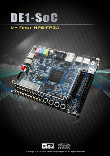
The HPS contains the following HPS-FPGA AXI bridges: FPGA-to-HPS Bridge HPS-to-FPGA BridgeLightweight HPS-to-FPGA BridgeFigure 1-1 shows a block diagram of the AXI bridges in the context of the FPGA fabric and theL3 interconnect to the HPS. Each master (M) and slave (S) interface is shown with its data width(s).The clock domain for each interconnect is shown in parentheses.Figure 1-1 AXI Bridge Block DiagramThe HPS-to-FPGA bridge is mastered by the level 3 (L3) main switch and the lightweightHPS-to-FPGA bridge is mastered by the L3 slave peripheral switch. In the Quartus of thisdemonstration, HPS-to-FPGA bridge is used for ARM/HSP to control the LEDs connected toFPGA.The FPGA-to-HPS bridge masters the L3 main switch, allowing any master implemented in theFPGA fabric to access most slaves in the HPS. For example, the FPGA-to-HPS bridge can accessthe accelerator coherency.All three bridges contains global programmer view GPV register. The GPV register control the5
behavior of the bridge. Access to the GPV registers of all three bridges is provided through thelightweight HPS-to-FPGA bridge.1.4. Source CodeThe demonstration source codes include a Quartus project and a C project. They are located in thefolder:CD-ROM\Demonstration\SOC FPGA\my first hps-fpgaThe Quartus Project is located in the sub-folder “fpga-rtl” and the C project is located in thesub-folder “hps-c”. In this tutorial, developer are expected to establish these projects from scratch.6
Chapter 2Quartus ProjectThis chapter introduces how the MY First HSP-FPGA Quartus project is created based on theDE1-SoC GHRD (Golden Hardware Reference Design) Quartus project. Based on the GHRDQuarturs project, a PIO component for controlling LED is added, and a connection between theslave port of the PIO component and the master port of HPS component is established.2.1. DE1-SoC GHRDDE1-SoC GHRD Quartus project is located in the DE1-SoCSystem CD folder:CD-ROM\Demonstration\SOC FPGA\DE1 SoC ghrdFor developers who wish HPS and FPGA can communicated with each other, they can develop anew project based on the golden Quartus project. This golden project includes all required pindeclares for both HPS and FPGA. Note, the pin declare of HPS only needs to specify pin directionand IO standard. Pin location is not required for the pin declare of HPS. The golden project alsoincludes basic Qsys system which already includes a HPS component. The HPS component hasbeen well-configured according to hardware design of DE1-SoC HPS.Developers can open the GHRD’s Qsys system by opening the GHRD Quartus project, and clickingthe menu item “Tools Qsys” in Quartus II. When Qsys tool is launched, it will ask user to select atarget Qsys system file. In this case, please select the Qsys file “soc system.qsys”. Figure 2-1shows the content of soc system.qsys Qsys system. It contains hps 0 HPS component.7
Figure 2-1 hps 0 HSP Component in Qsys System of DE1-SoC GHRDFigure 2-2 shows the lightweight HPS-to-FPGA AXI Master port of the HPS component.Developers can connect this port to any memory-mapped slave port of components which developerwish to access from HPS/ARM.Figure 2-2 AXI Master Port of HPS component8
2.2. Create a Quar tus ProjectThis section will show how to add a PIO component in Qsys and connect the PIO component to theHPS component. The PIO component is used to control the ten red LEDs connected to FPGA. First,please copy the DE1-SoC GHRD Quartus project to local disk. Open the project and open the Qsyssystem file “soc system.qsys”.In the Library dialog of Qsys tool, enter ‘pio’ search key as shown in Figure 2-3. When “PIO(Parallel I/O)” appears, select it. Then, click “Add ” to add the PIO component to the system.Figure 2-3 Find and Add PIO ComponentWhen PIO dialog appears, please change Width to 10, make sure “Output” Direction is selected,and change the Output Port Reset Value to 0x3ff as shown in Figure 2-4.9
Figure 2-4 Configure PIO ComponentWhen the PIO component is added into the system, please connect the h2f lw axi master AXImaster port to the s1 slave port of the PIO component as shown in Figure 2-5. By the way, pleasechange PIO component name to pio led, change the Clock Input to clk 0, export the Conduitsignal as pio led external connection, and connect the Reset Input to system reset. Note, theBase address of pio led PIO component is very important. The ARM program will access thecomponent according to this base address. In this demonstration, the base address is fixed at0x0000 0000. The ARM program developer should remember this base address or use a givenLinux shell batch file to extract the address information to a header file hps 0.h. The detailprocedure will be described in the next chapter.Figure 2-5 Create Connection Between HPS and PIO componentIn the Qsys tool, click menu item “Generate HDL Example ” can find the new interface signalpio led external connection export for the added pio led PIO component as shown in Figure2-6. Developer can click ‘Copy’ to copy the content to a clipboard, then paste thepio led external connection export signal to Quartus top and connect it to the LEDR port asshown in Figure 2-7. Before closing the Qsys tool, please remember to click the menu item“Generate Generate ” to generate source code for the system.10
Figure 2-6 pio led Interface of SystemFigure 2-7 Initialize .pio led external commection export in u0 soc system2.3. Compile and ProgrammingNow, developers can start the compile process by clicking the menu item “Processing StartCompilation”. When the compilation process is completed successfully, soc system.sof isgenerated. Developers can use this file to configure FPGA by Quartus Programming through theDE1-SoC on-board USB-Blaster II.11
Because .tcl files of SDRAMM DDR3 controller for HPS had been executed in GHRD Quartusproject, so developers can skip these projects. If developers’s Quartus project is not developedbased on the GHRD Quartus project, please remember to execute the .tcl files, as show in Figure2-8, before executing ‘Start Compilation’. The TCL Scripts dialog can be launched by clicking themenuitem“Tools TCLScripts ”. qsys system name parameters.tcland qsys system name pin assignments.tcltclfilesshouldbeexecuted,where qsys system name is the name of your Qsys system. Run this script to assign constrains tor theSDRAM DDR3 component.Figure 2-8 TCL file for SDRAM DDR3 of HPS12
Chapter 3C ProjectThis chapter introduces how to design an ARM C program to control the pio led PIO controller.Altera SoC EDS is used to compile the C project. For ARM program to control the pio led PIOcomponent, pio led address is required. The Linux built-in driver ‘/dev/mem’ and mmapsystem-call are used to map the physical base address of pie led component to a virtual addresswhich can be directly accessed by Linux application software.3.1. HPS Header Filepio led component information is required for ARM C program as the program will attempt to control thecomponent. This section describes how to use a given Linux shell batch file to extract the Qsys HPSinformation to a header file which will be included in the C program later.The batch file mentioned above is called as generate hps qsys header.sh. It is located in the samefolder as my first hps-fpga Quartus project. To generate the header file, launch Altera SoC EDScommand shell, go to the Quartus project folder, and execute generate hps qsys header.sh bytyping ‘./generate hps qys header.sh” followed by ENTER key. A header file hps 0.h is generated.In the header file, the pio led base address is represented by a constant PIO LED BASE as showin Figure 3-1. The pio led width is represented by a constant PIO LED DATA WIDTH. Thesetwo constants will be used in the C program demonstration code.13
Figure 3-1 pio led information defined in hps 0.h3.2. Map pio led AddressThis section will describe how to map the pio led physical address into a virtual address which isaccessible by an application software. Figure 3-2 shows the C program to derive the virtual addressof pio led base address. First, open system-call is used to open memory device driver “/dev/mem”,and then the mmap system-call is used to map HPS physical address into a virtual addressrepresented by the void pointer variable virtual base. Then, the virtual address of pio led can becalculated by adding the below two offset addresses to virtual base. Offset address of Lightweight HPS-to-FPGA AXI bus relative to HPS base address Offset address of Pio led relative to Lightweight HPS-to-FPGA AXI busThe first offset address is 0xff200000 which is defined as a constant ALT LWFPGASLVS OFST inthe header hps.h. The hps.h is a header of Altera SoC EDS. It is located in the folder:Quartus Installed Folder\embedded\ip\altera\hps\altera hps\hwlib\include\socalThe second offset address is 0x00000000 which is defined as PIO LED BASE in the hps 0.hheader file which is generated in above section.The virtual address of pio led is represented by a void pointer variable h2p lw led addr.Application program can directly use the pointer variable to access the registers in the controller of14
pio led.Figure 3-2 pio led information defined in hps 0.h3.3. LED ControlC programmers need to understand the Register Map of the PIO core for pio led before they cancontrol it. Figure 3-3 shows the Register Map for the PIO Core. Each register is 32-bit width. Fordetail information, please refer to the datasheet of PIO Core. For led control, we just need to writeoutput value to the offset 0 register. Because the led on DE1-SoC is low active, writing a value0x00000000 to the offset 0 register will turn on all of the ten red LEDs. Writing a value 0x000003ffto the offset 0 register will turn off all of ten red LEDs. In C program, writing a value 0x000003ff tothe offset 0 register of pio led can be implemented as:*(uint32 t *) h2p lw led addr 0x000003ff;The state will cast the void pointer to a uint32 t pointer, so C compiler knows write a 32-bit value0x000003ff to the virtual address h2p lw led addr.15
Figure 3-3 Register Map of PIO Core3.4. Main ProgramIn the main program, the LED is controlled to perform LED light sifting operation as shown inFigure 3-4 . When finishing 60 times of shift cycle, the program will be terminated.Figure 3-4 C Program for LED Shift Operation16
3.5. Makefile and compileFigure 3-5 shows the content of Makefile for this C project. Because the program will include thehps.h provided by Altera SoC EDS, so the Makefile should include the following path:“ {SOCEDS DEST ROOT}/ip/altera/hps/altera hps/hwlib/include”In the makefile, ARM cross-compile also be specified.Figure 3-5 Makefile contentTo compile the project, type “make” as shown in Figure 3-6. Type “ls” to check the generatedARM execution file “my first hps-fpga”.Figure 3-6 ARM C Project Compilation17
3.6. Execute the DemoTo execute the demo, please boot the Linux from the SD-card in DE1-SoC. Copy the execution file“my first hps-fpga” to the Linux directory, and type “chmod x my first hps-fpga” to addexecution attribute to the execute file. Use Quartus Programmer to configure FPGA with thesoc system.sof generated in previous chapter. Then, type “./my first hps-fpga” to launch the ARMprogram. The LED on DE1-SoC will be expected to perform 60 times of LED light shift operation,and then the program is terminated.For details about booting the Linux from SD-card, please refer to the document:DE1-SoC Getting Started Guide.pdfFor details about copying files to Linux directory, please refer to the document:My First HPS.pdf18
This tutorial is meant for any SoC FPGA starters who wants to know more about how to use the HPS/ARM to communicate with FPGA. The "My First HPS-FPGA" project is used to demonstrate . In Altera SoC FPGA, the HPS logic and FPGA fabric are connected through the AXI (Advanced eXtensible Interface) bridge. For HPS logic to communicate with .