Transcription
HEC-RAS 2DFlood ModellingTutorial
HEC-RAS 2D Flood Modelling TutorialCivil Site Design and HECRAS 2D Flood ModellingHECRAS version 5 and later includes functionality to analyse waterflows moving across a surface. this is known as 2D flood modellingand provides more accurate modelling of water movement across asurface than 1d (or section based) flood modelling.If you are using Civil Site Design, you now have functionality to workwith HECRAS input and output files via the Export HECRAS 2D andImport HECRAS 2D commands.For this example, we’ll use HECRAS to undertake a 2D flow analysis ofan existing creek abutting an existing car park being considered forexpansion. The existing creek flow performance is to be maintainedfollowing the new works, and enhancement of the creek flow may berequired if flooding is occurring downstream.A peak flow of 10m3/s must be managed in the creek.The Tutorial Data SetThe tutorial data is installed with the software installation to the following location(Note: the HEC-RAS menu must be ticked on for inclusion during install):Civil 3D: C:\CSS Training Data\Civil Site Design\HEC-RAS\HECRAS 2D Tutorial – Start.dwgCAD: C:\CSS Training Data\Civil Site Design\HEC-RAS\HECRAS 2D Tutorial – Start - CAD.dwgThis drawing file includes a surface and is located in the MGA-55 Coordinate system.At this stage, there is no surface associated with the data set. This can be remediedusing Model Viewer. To do this: Start the ribbon command Roads Tab Select Panel Model Viewer. This will start Model Viewer and populatethe existing surface name into the Toggle Display formUnder Base Surface, click on the picklist dropdown forStyle and select Image from Satellite (Aerial Photo) The Satellite Setup formwill display. Firstly click onthe button, selectAustralia MGA-55.prj fromthe list and click OK. Click on Confirm SatelliteData to see the imagery available under the surface location. Roll the mouse to zoom out but 3 steps only (the more zoom out, theless quality) and click the Accept button top left. Click OK to exit the Toggle Display form. An image is associated with thesurface in Model Viewer.2
HEC-RAS 2D Flood Modelling TutorialFor AutoCAD and Civil 3D users, an image is also inserted in the drawing.For BricsCAD users, an image is saved to the –Data folder. When inserted into the drawing it will automaticallyposition itself correctly.Exporting Terrain Data to HECRASThe Export HECRAS 2D command will take the combination of your design and existing surfaces and share themacross to HECRAS as a single geotiff file. The goetiff describes the surface extents and elevations for HECRAS. Thecommand can be run directly from the ribbon interface, or can be run from inside Model Viewer.If you opt to run the command from the CAD ribbon interface, the Toggle Display form will display for you toconfirm what surface data to bring across to HECRAS - you can opt to just include the existing surface conditions,or you could send across a combined surface containing the existing surface as well as your design surfaces. Thiswould enable you to analyse pre and post development conditions. If you run the command from inside ModelViewer, you get the benefit of directly reviewing the surface before export across to HECRAS.In the Export HECRAS 2D command you need to specify a location and name for the geotiff you are exporting, aswell as a grid spacing. Set a grid spacing that matches the accuracy of the data you have, to ensure you don't loseinformation and, conversely, you don't include unnecessary data.Once you have a geotiff file you can use this to generate terrain data in HECRAS.Steps:1. If you closed Model Viewer, click on the ribbon command Roads Tab Select Panel Model Viewer. Thiswill start Model Viewer.3
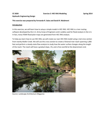
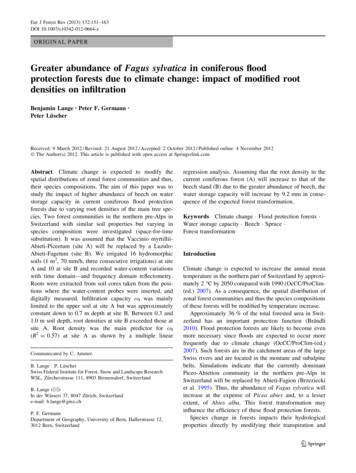
HEC-RAS 2D Flood Modelling Tutorial2. If required, confirm the settings via Toggle Display. If the previous steps are complete, the surface andimage required to be analysed in HECRAS should already by shown.Note: in the above image the exaggeration has been set to 5 to accentuate the shape of the terrain.Exaggeration must be set to 1 before exporting3. Click on the Analyse Tab HECRAS 2D Panel Export buttonIn the Export form you confirm the location, name and grid size of the file to export.4. Leave the Grid Spacing to the default of 15. Note the path to the output HECRAS file, then click Export to create a HECRAS input file.4
HEC-RAS 2D Flood Modelling TutorialImport and Analysis in HECRASAfter starting your HECRAS project and establishing the units and setup, you need to open RAS Mapper andcreate a terrain. You will firstly set up a projection, or coordinate system, for your data.HECRAS Project Setup6. Click on File New. Select a location and name for the new project.7. Click on Options Unit System to confirm the units (this example is using Metric units).HECRAS RAS Mapper8. From the HEC-RAS interface, select GIS Tools RAS Mapper or else click on the RAS Mapperbutton.The RAS Mapper form will display with a menu at the top and a list of layers along the side. The first task is topopulate the Terrain layer using the .tif created by Civil Site Design. Optionally, a Map Layer can be included forthe aerial photo.Assigning a ProjectionBefore creating a terrain, a projection must be set. This is controlled by a projection file, extensIon .prj. Sometypical Australian and other country specific .prj files are contained in the Civil Site Design Settings folder, in theVisualisation and then Projections folders. There is also a website where you can generate .prj files by typing inyour location.9. From the Ras Mapper form, click on Tools Set Projection for Project.For this example, a .prj has been provided in the same directory as the tutorial drawing: C:\CSS Training Data\CivilSite Design\HEC-RAS10. Navigate to the above folder location and openAustralia MGA-55.prj. This assigns the Projection.After selecting the .prj file click OK to apply theprojection.5
HEC-RAS 2D Flood Modelling TutorialAdding a TerrainWhen you open the Terrain form and create a new Terrain, you will have an opportunity to load a terrain file here you can use the exported file from Civil Site Design to generate the terrain data for HECRAS.11. Click on Tools New Terrain12. Click on to add a new data source for the terrain. Navigate to the output location of the .tif and openthat fileThis data will be used to create a Terrain – in HECRAS the terrain is saved as a file with extension .hdf.13. Click on Create to import the Terrain.14. Note under the Terrains layer is a new layer. Make sure that Terrains is ticked on, then right click onTerrain and choose Zoom to Extents to see the full extents of the terrain model in RAS Mapper.6
HEC-RAS 2D Flood Modelling TutorialAdding an Aerial PhotoWith RAS Mapper you can also include imagery and other geospatial data.15. Right click on Map Layers and follow the Map Data Layers flyout to select Add Existing Layer.When prompted to select a file, use the file type dropdown at the bottom right to select Other (*.*).Selecting a .jpg file will then insert it into HECRAS so long as it is accompanied by a world file (.jgw filecontains the spatial location for a .jpg file).16. Select the image file output during step 5 above or C:\CSS Training Data\Civil Site Design\HECRAS\VisSatellite.jpgTick on the image to display it in RAS Mapper. Right click on the image name to edit the Image DisplayProperties – a transparency can be assigned here.7
HEC-RAS 2D Flood Modelling TutorialAfter importing data into RAS Mapper, it will become available in the HECRAS Geometry Editor. In here you canassign flood data along the boundaries, establish the model grid size for flood analysis, edit the surface breaklines,assign different surface Manning's n values and more.Close RAS Mapper.Creating the 2D Flow Area17. From the HEC-RAS interface, click on View/Edit Geometric DataA new form will display entitled Geometric Data. The surface will initially display with the colours representingelevations. To show the aerial photo, click onand tick on to display the Map Layer you added.8
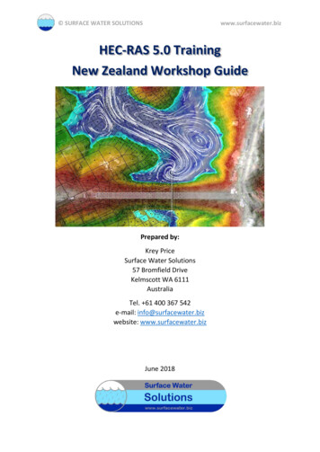
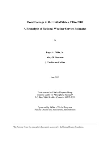
HEC-RAS 2D Flood Modelling TutorialThe linework in your original drawing can be included in the Geometric data as a layer, after exporting it out fromthe drawing in an appropriate format for HECRAS.Now to create a 2D flow area for analysis. To keep it simple, select the extents of the terrain as the boundary.This is a relatively well defined basin, so the extents of the boundary are typically much higher than the creek(excepting the inflow and outflow locations north and south). When you select the area you can establish acalculation mesh across the surface. In our example, a 10m mesh is suitable and matches with the existingsurface triangulation.18. Click on the 2D Flow Areabutton. Use the left mouse button to sketch the boundaries of a flowarea. Double click on the start of the first line drawn to close the area.19. At the prompt, name the area Total FlowArea and click OK.9
HEC-RAS 2D Flood Modelling Tutorial20. Left click on the new area and select Edit 2D Flow Area In the 2D Flow Areas form you apply a computational mesh across the surface, as well as establish Manning’s nvalues to apply for the default area and for any other Land Cover areas added.21. Click on Generate Computation Points on Regular Interval with All Breaklines 22. Set DX and DY both to 10 and click Generate Points in 2D Flow Area23. Click OK to close the 2D Flow Areas form.The pattern on the 2D flow area in the Geometric Editor will change – zooming in will expose theindividual mesh areas. Zoom in to view the mesh shape. If any are red in colour then you will need to usethe Edit Add Points command to add more mesh point or else adjust the boundary shape.Note: if it is required to edit the outline of the 2D flow area, use the menu command Edit Move Points/Objects orother edit tool in the Edits menu.10
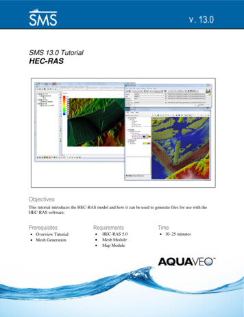
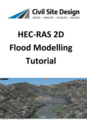
HEC-RAS 2D Flood Modelling TutorialThe 2D Area Breaklinescommand can be used to incorporate breaklines into the flow area to betterrepresent ridge and valley lines for the surface.Setting Boundary Conditions (for Incoming and Outgoing flows)Flow comes from the ponding areas along the southern boundary of the surface, so a boundary condition needsto be set along this edge. We can then assign inflow along this boundary to spill across the surface. The low sideof the surface is along the northern boundary, so we can set a boundary condition along there for how water canexit along that boundary.24. Click on the SA/2D Area BC Lines button25. Click inside the 2D Flow Area along the southern boundary to set an incoming flow line. Flow will come inuniformly along this line. Double click to finish the boundary26. Name the boundary Inflow and click OK to create.27. Repeat the above 3 steps to create an ‘outflow’ boundary. Run the boundary just outside the 2D FlowArea along the west, north and eastern boundary where the properties are and name the flow areaboundary Outflow. The outputs should look similar to below:11
HEC-RAS 2D Flood Modelling TutorialNote that in the geometry editor you can incorporate both 1D and 2D flow zones into a single model for analysis.Additionally, boundary conditions can be set within the 2D area to represent different hydraulic behaviours. Aftersetting up the surface and boundary conditions, you can move onto assigning the flow conditions.28. Click on File Save Geometry Data.29. Name the file Existing Conditions and click OKNote: Where a boundary is not specified, water is assumed to well up along the boundary as if the boundary edgewas a wall.Establish Flow Conditions along the BoundariesIn the Flow Conditions form, we can set an inflow for the Inflow incoming boundary along the southern boundary.In this example, we're working with a peak flow of 10 m3/s and describing the storm shape as a simple bell typecurve. You can copy and paste from spreadsheet input tools, such as Excel, to quickly create the flow informationfor HEC-RAS. For the outgoing boundary conditions, we set for a normal depth and apply a friction slope todescribe how the exiting flow is handled.30. From the HECRAS menu click on View/Edit Unsteady Flow dataA new form will display entitled Unsteady Flow Data. The form will list thetwo Boundary Conditions set for the 2D area.31. Under Add Boundary Condition Location, click on Add SA/2D FlowArea to include the Total Flow area32. Click on the - arrow to include the Total Flow Area for analysis and click OK.Next, we set the outflow conditions along the northern boundary line we’ve created.33. Under Storage/2D Flow Area, click the flow area entitled Outflow34. Click on Normal Depth at the top to establish the outflow conditions along this line35. Type in a Friction Slope of 0.1 and click OKThe Boundary Condition for the Inflow will be set to Normal Depth.12
HEC-RAS 2D Flood Modelling TutorialNow we need to assign incoming flows into the system.36. Under Storage/2D Flow Area, click on the flow entitled Inflow37. Click on Flow Hydrograph to assign a time dependent flow to thisinflow lineFor Data Time Interval, set the value to 1 hr using the pick listTo add flows you can type in a Flow for each time step (0 to 48hrs)and set for a build up to a peak flow of 10m3/s, however it is oftenquicker to spreadsheet out the required flow characteristics, copythem from Excel, and use the paste command to paste them into theFlow column.For this purpose, you may wish to open the file Storm Input Calculator.xls file located in the same directory asthe source drawing. In this file, you can type in the Minimum and Maximum flow values at the top of theform and it will populate values for 1hr increments.Set the Maximum Flow to 10m3/s (or higher if you wish). Then highlight the values in the Flow column andcopy to clipboard (Ctrl C or right click and select Copy). In the Flow Hydrograph form, highlight all Flow cellsfrom 0:00 to 48:00 a
Select the image file output during step 5 above or C:\CSS Training Data\Civil Site Design\HEC-RAS\VisSatellite.jpg Tick on the image to display it in RAS Mapper. Right click on the image name to edit the Image Display Properties – a transparency can be assigned here. HEC-RAS 2D Flood Modelling Tutorial 8 After importing data into RAS Mapper, it will become available in the HECRAS Geometry .