Transcription
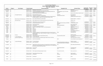
TRANSPORTATION RESEARCH RECORD 142014U.S. Army Corps of Engineers RiprapDesign for Flood ChannelsSTEPHENT.MAYNORDThe U.S . Army Corps of Engineers riprap design guidance forflood channels is presented, and the limitations and basis of several empirical coefficients are discussed. The method is based ondepth-averaged velocity rather than shear stress, which was thebasis of the previous guidance. The effects of bends, blanketthickness, side-slope angle, particle shape, and gradation on riprap stability are addressed in the design guidance.D 85 ID 15 Cv The U.S. Army Corps of Engineers guidance for design ofriprap in flood control channels is found in Engineer Manual(EM) 1110-2-1601 (J). This guidance is a departure from thetraditional guidance based on shear stress or tractive forceand uses a procedure based on local depth-averaged velocity.Although the new method can be derived from a modificationof the shear stress equations, it does not use shear stressexplicitly. Local depth-averaged velocity was adopted primarily because local shear stress is difficult to visualize, compute, and measure. Various methods, discussed in this paper,are available for estimating depth-averaged velocity. The objective of this paper is to provide assistance in application ofthe new procedure. Limitations of the method and severalexample problems will also be presented.BASIC EQUATIONThe basis and derivation of the basic equation used to determine stone size can be found in works by Maynord (2 ,3) andMaynord et al. (4). From EM 1110-2-1601 (J) the equationfor determining stone size is(J) is incorrect, giving 0.36];gradation uniformity coefficient;vertical velocity distribution coefficient,1.0 for straight channels inside of bends,1.283 - 0.2 log (RIW) for outside of bends (1for RIW 26),1.25 downstream of concrete channels, and1.25 at end of dikes;centerline radius of curvature of bend;water-surface width at upstream end of bend;blanket thickness coefficient (see Figure 1);local depth of flow;unit weight of water;unit weight of stone;local depth-averaged velocity;side-slope correction factor; andgravitational constant. 0.375 for rounded rock [note: EM R W CT d 'Yw 'Ys V K1 g The power of 2.5 in this equation was based on laboratorydata from straight, tilting flumes. The extreme values of thepower in Equation 1 are from 2 to 3. A power of 2 results inthe Isbash equation (no dependence on depth) and is generallyused when there is no boundary layer development. A powerof 3 results from application of existing shear stress and theManning-Strickler equations and represents the condition ofcompletely developed boundary layer and a relative roughness (roughness size/depth) that is low enough to yield a constant Shields coefficient. Because most bank and channel riprap protection problems fall somewhere between these twoextremes, the 2.5 power was adopted for all bank and channelriprap protection problems, not just the straight, tilting flumesfrom which it was derived.(1)whereD 30 riprap size of which 30 percent is finer by weight(for some gradations, use D,);D, D 8s(min)[D 15 (min) 2 ];sf safety factor (minimum 1.1);Cs stability coefficient for incipient failure, thickness 1D 100 (max) or l.5D 50 (max), whicheveris greater (D 851D 15 1. 7 to 5.2), 0.30 for angular rock, andU.S. Army Engineer Waterways Experiment Station, 3909 Halls FerryRoad, Vicksburg, Miss. 39180-6199.INPUT/OUTPUT DESCRIPTION ANDLIMITATIONSGeneralThe method described herein is limited to what is normallyreferred to as "low turbulent flow": the method is applicableto sizing riprap in rivers and channels except those immediately downstream of hydraulic structures that create highlyturbulent flow. Data used in the development of this methodwere limited to slopes less than or equal to 2 percent. Dataare also limited to D 3 ofd;::: 0.02, which means that the methodhas not been verified for relatively deep flows.
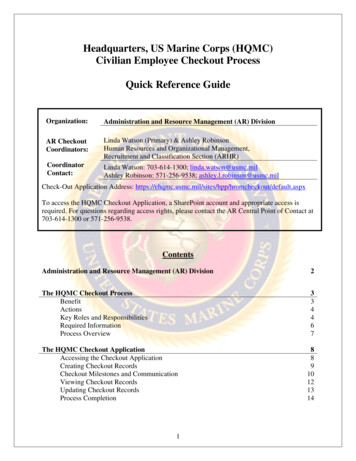
15Maynord1.0 .r-.-----'-.c,"""0.5 2.15.2 D95/D15'" D95 ID152.5 ABT ET AL (l 988J D95ID151.7 INTERPDLA TED J- -D95/D\50.01.0 I2.52.01.5N THICKNESSTVHERE CT CORRECTIONFOR THICKNESSD30 FOR THICKNESS OF NT D 30 FOR THICKNESS OFT Tl ID IOO OR 1.5D 50 , VHICHEVER IS GREATERFIGURE 1 Correction for riprap blanketthickness.Design ConditionsRiprap should be designed for the combination of velocityand depth that gives the largest rock size. This combinationis not always the design discharge. In many cases bank-fulldischarge produces the combination of velocity and depth thatresults in the largest rock size . Rock size in bendways is normally based on the maximum velocity-depth combination foundalong the bend. Bendways having stable upstream conditionscould be designed with a variable rock size along the bend.This is generally not done because specifying multiple gradations has been found in some cases to increase constructioncosts.1. Two-dimensional (2D) depth-averaged numerical modelshave been shown to be unconservative in prismatic bends.Bernard (5) has developed a correction method for 2D depthaveraged models, and a version is available that can be usedwith 386 personal computers (PCs). This model has comparedwell with data from trapezoidal channels and is being testedagainst data from natural channels.2. Physical models are rarely available for bank protectionprojects because of cost. If available , near bank velocity distributions should be measured to obtain vss 3. Empirical methods must be applied only to cases similarto the data from which they were derived .4. Analytical methods, which are based on conveyance (suchas the ALPHA method given in EM 1110-2-1601 (J)] , shouldbe limited to straight channels because secondary currentscause ALPHA to be unconservative. Thorne and Abt (unpublished data) discuss additional analytical methods that incorporate the effects of secondary currents.5. Prototype data normally require extrapolation to designconditions but are usually not available.This paper focuses on the application of the empirical methodgiven in EM 1110-2-1601 (J), presented in Figure 2. Figure 2is applicable only for estimating characteristic side-slope velocity (V,,) in straight or curved channels at 20 percent ofslope length up from the toe . Figure 2 was derived fromvelocity data taken in physical models and prototypes. Theamount of scatter in this type of data is large, and the curveswere drawn on the conservative side of the data. In the caseof bendways , Figure 2 is based on bends having fully devel-Velocity EstimationAs stated earlier , the primary reason for adopting a designprocedure based on depth-averaged velocity is that severaltechniques exist for estimating this velocity. Velocity is alsoeasier to visualize and measure than is shear stress. Any riprapdesign problem has two parts: the first part is to estimate theimposed force, and the second is to use the imposed forceand determine riprap size. The most difficult and most uncertain part of riprap design lies in estimating the imposedforce, whether it be local depth-averaged velocity or shearstress. When riprap is designed for a channel bottom, localdepth-averaged velocity is a straightforward concept even ifit is difficult to determine. When side-slope riprap is designed ,local depth-averaged velocity varies greatly from the toe ofslope to the waterline, and near-bank velocity is meaninglessunless the position is specified. The EM 1110-2-1601 method(1) uses depth-averaged velocity at a point 20 percent upslopefrom the toe V,, for side-slope riprap design. The 20 percentpoint was selected because straight channel side-slope stabilitytests resulted in the same stability coefficient Cs as straightchannel bottom stability tests with this position on the sideslope and the appropriate adjustment for side-slope angle.This point is consistent with the location of maximum sideslope shear stress from straight channel studies.Various tools exist to estimate depth-averaged velocity foruse in riprap design and include the following with some oftheir limitations:1.61.4 1.71 - 0.78 LOG (R/\J)Vuvg OJ o 1.2'111111 1.0 ""' 0.8246820104050R/'v/1.61.4vss -v--""- u vg 1.74 - 0.52 LOG Rl\J) I'--- """-1.0 '---0.82468102040R/'v/FIGURE 2 Velocity estimation based on EM 1110-2-1601 (J):top, trapezoidal channel; bottom, natural channel.50
16TRANSPORTATION RESEARCH RECORD 1420oped bend flow, which means that the bend angle is sufficiently large to develop close to the maximum velocity forthat value of RIW. To use the minimum Vs.fV.vg in Figure 2for straight channels requires that the channel be far enoughdownstream of bends , constrictions, or other devices that mightcreate an imbalance of flow across the channel. Consequentlyone should be very cautious about specifying a straight channel-some investigators will not use Vss!V.vg 1. Figure 2estimates V., from only average channel velocity V. vg, R, W,and channel type (natural or trapezoidal) . The effects of otherfactors such as bend angle, bank angle, and bed/bank roughness have not been determined. It is important to note thatVsJVavg has rarely been found to exceed 1.6 in any alluvialor man-made fixed bed channel and is a minimum of 0.82 instraight trapezoidal channels and 0.9 in straight natural channels. Thus the designer is simply defining where in the rangeof Vss/Vav 0.82 to 1.6 to design the protection. Figure 2assists in that determination and generally provides a conservative estimate. Since Figure 2 is valid only for estimatingside-slope velocity , velocity estimation for all problems otherthan bank protection (such as channel bottom protection)must use some other technique to determine local depthaveraged velocity, such as the numerical model described previously .Average channel velocity is used only in the EM method(1) in conjunction with the empirical velocity estimation technique and is determined from discharge/channel area (Q/A).Area and discharge should be restricted to the main channeland should not include overbank areas .Characteristic Particle Size for GradationOne of the most controversial changes from the old to thenew guidance has been the adoption of a characteristic particlesize of D 30 A gradation plot in Figure 3 illustrates conceptssuch as the lower and upper gradation limits (also referred toas minimum and maximum) as well as D 100 (max), D 30 (min),and so forth. Stability tests conducted at a thickness of lD 100 ,which is the most commonly used thickness for bank protection, showed that gradations ranging from uniform to highlynonuniform exhibited the same stability if they had the sameD 30 Maynord provides details of the comparison of D 50 andD 30 and documents other investigators who found a characteristic size less than the commonly used D 50 (2) . It is likelythat if the tests had been conducted at another thickness, suchas l.5D 100 , the resulting characteristic size would have beendifferent, probably larger. The use of D 30 instead of D 50 requires that the designer determine which of the available gradations has a D 30 (min) greater than or equal to the computedD 30 rather than to D 50 One of the results of this finding isthat uniform gradations use the least volume of rock to achievethe same stability because the thickness is equal to the maximum stone size . One of the troubling aspects of these resultsis that an investigator of riprap subjected to channel flow hasnot yet been found who has been able to confirm the commonly held notion that a range of sizes gives increased stabilitydue to better interlock.If the designer prefers to work in terms of D 50 , the approximate relation of D 30 is(2)Bend Radius and Water-Surface WidthThe centerline radius of curvature of the bend and the watersurface width at the upstream end of the bend are used tocharacterize the bendway in both the EM rock sizing techniques (J) and the scour depth estimation techniques. Thecenterline radius and the width should be based on flow inthe main channel and should not include overbank areas.The use of a single particle size to characterize a gradation,whether D 30 (min) or D 50 (min) , does not reflect all characteristics of that gradation. The following equation can be usedto determine if D 30 (min) is representative or if D,(min) shouldbe used as the characteristic particle size: D 85 (min)[D 15 (min) 2]D,(min) (3)Natural Versus Trapezoidal Channel100In the empirical velocity estimation technique shown in Figure2, two channel types, natural and trapezoidal, are used . Trapezoidal channels are often man-made with a smooth alignment; sediment transport is not sufficient to build point bars,which can concentrate flow against the outer bank. The dataused in developing the trapezoidal channel curve were fromclearwater channel models having riprap bottom and banksand aspect ratios (top width/average depth) ranging from 11to 22. Though many trapezoidal channels have aspect ratiosgreater than 22, secondary currents in the channels with loweraspect ratios will provide more velocity concentration alongthe outer bank than those with higher aspect ratios.In contrast, the natural channel curve in Figure 2 is applicable to channels having irregular alignment with sedimenttransport leading to point bars and toe scour that concentratethe flow along the outer bank.90f-D 85(Min) 8.2 IN.3 -CD,,,zQ'. MINIMUM ORLOVER LIMIT -605040 . o, i:' / v3020/ 12 IN.-.MAXIMUM OR UPPER LIMITJ/JI/I/( l'\Q X)/-/IlL"1JJ70100/80I8w/'nI-INOTE LIMITS SHO\JN AREFDR ETL 1110-2-120JGRADATION (6l HAVINGD lOO10(Max) 12 IN.1 IN. 25.4 MM045678910DI AMETER, IN .FIGURE 3 Explanation of gradation terminology.20
Maynord17If D,(min) is significantly different from D 30(min), use D,(min).The significance of Equation 3 is explained elsewhere (3).One factor that should be considered is the impact of gradation on filter requirements. If a granular filter is used, thelower sizes of the riprap gradation must properly interfacewith the upper sizes of the filter. Consequently it is difficultto use a large uniform riprap and economically interface itwith a granular filter. With geotextiles , this is not a problem,but a bedding layer is sometimes used on top of the geotextileto prevent damage from placing the riprap.Unit Stone WeightUnit stone weight is generally within the range of 2402 to2803 kg/m3 (150 to 175 lb/ft 3 ). Rock weighing less than 2402kg/m3 (150 lb/ft 3 ) can be used, but this is not very close tothe unit weights that have been used in stability tests. Whenrock sizes required for different unit weights are compared,it is not correct simply to use equal rock weights and therelationship between size and weight of a sphere or cube.These comparisons must be made using the stone-sizing Equation 1 because this addresses the increased drag that wouldoccur on a less dense but larger piece of riprap.Riprap Blanket ThicknessBlanket thickness is generally measured in terms of the maximum stone size D 100 The minimum allowable blanket thickness is 1D 100 , and many streambank protection projects use .this thickness . Only for very uniform gradations (D 85 /D 15 2) must the thickness also be at least l.5D 50 Stability testsshow that uniform gradations must meet this requirement ofl.5D 50 (max) for equivalent stability. Stability tests have shownthat a thickness greater than T*, where T* is the greater ofl.5D 50 or l.OD 100 , results in increased stability. Figure 1 showsguidance given in EM 1110-2-1601 (1) for thickness effects.The interpolated curve having D 8 s/D 15 1.7 is applicable tothe gradations in Table 1 (6). (This curve was interpolatedbetween the curve for D 851D, 5 2.5 and D 8 s/D 15 1, whichwas conservatively assumed to have no increase in stabilityfor increased thickness .) Gradations having D 8 sfD 15 5.2should use the curve for 5.2. When greater blanket thicknessis used to increase stability, it must be realized that some rockmovement will occur before the revetment becomes stable.Local Flow DepthThe procedure presented in EM 1110-2-1601 is based on localdepth-averaged velocity and local depth of flow. For channelbottoms, the local depth of flow is simply the depth at thepoint of interest. For side slopes the characteristic velocityand local depth are located 20 percent up the slope from thetoe. At this point the local depth is 80 percent of the depthover the toe.Side-Slope AngleStability studies have shown that the decrease in stability thatoccurs from placing a revetment on a side slope is not assignificant as suggested in some of the previous guidance. Thisis probably because the angle of repose of a revetment isgreater than the angle of repose of a rock dike. The relationof K 1 versus side-slope angle from EM 1110-2-1601 is shownin Figure 4. The solid line should be used for revetments. Theleast volume of riprap per foot of bank line is used whenrevetments are placed on slopes between 1V: l .SH and 1V :2H.For slopes flatter than 1V:4H, rock stability is not affectedby the slope angle for revetments subject to channel flow.Slopes steeper than 1V:l.5H are not recommended.Velocity Profile CorrectionAn evaluation of the velocity profile over bottom riprap instraight channels resulted in the following equation:TABLE 1 Gradations for Specific Stone Weight of 165 lb/ftJ, from ETL 1110-2-120 (6)D100 (max)(in.)121518212427303336424854Limits of Stone Weight for Percentage Lighter byWeight 492D30 (min)(ft)0.480.610.730.850.971.101.221. 341.461. 701. 952.193NOTE: 1 lb/ft 16.018 kg/m3 ; stone weight limit data from ETL 1110-2-120 (6).Relationship between diameter and weight is based on the shape of a sphere.D90 (min)(ftl0.70O.BB1. 061.231.401. 591. 771.962 .112.472.823.17
TRANSPORTATION RESEARCH RECORD 1420181.00.8v- -T0.6Ki-- /,,.v.-Cv 1.283 - 0.2 log (RIW)I0.4----e---0.0RECOMMENDED FDR DESIGNCARTE CARLSD ANDLANE CB m 40 DEGwhere Cv is equal to 1 for R/W 2: 26.A third area where the velocity profile departs significantlyfrom Equation 4 is riprap on the nose of a rock dike. Theconstricting effect of the dike causes the flow to acceleraterapidly around the dike . Because of the short distance , theflow is affected by the dike and the boundary layer has nochance to grow and is continually being reduced by the flowacceleration. Limited tests show that the velocity profile correction to be multiplied by the rock size should be 1.25 forriprap on the nose of a dike .ILO2.0COTe304.0 FIGURE 4 Side-slope correction coefficient.V )(5)Il t - -0.2,Waterways Experiment Station, the empirical velocity profilecorrection to be multiplied by the computed rock size wasfound to be 1.2 for R/W 2.5. The relationship used for thevelocity profile correction given in EM 1110-2-1601 is. (1 N)( fStability Coefficient(4)whereV(y) velocity at y,N 0.25 for d/D 90 from 3 to 20, andy distance from top of riprap.The velocity profile given by Equation 4 is the profile forwhich the stability coefficient for angular rock was found tobe 0.30. In both bendways and just downstream of concretechannels, the profile is more nearly vertical with velocity inthe upper zone (near the surface) less than Equation 4 andvelocity in the lower zone (near the bottom) greater thanEquation 4. For the same depth-averaged velocity , the verticalvelocity profile in bends and just downstream of concretechannels tends to have a greater capacity to move the riprapbecause the velocities near the riprap and the shear stress arelarger. For riprap just downstream of concrete channels, thevelocity profile has not adjusted from the smooth concretesurface to the rough riprap. For bendways, secondary currentsare suspected of causing the change in velocity profile.In either case, an increased stone s
ness (roughness size/depth) that is low enough to yield a con stant Shields coefficient. Because most bank and channel rip rap protection problems fall somewhere between these two extremes, the 2.5 power was adopted for all bank and channel riprap protection problems, not jus