Transcription
User manual2018/08/01
DisclaimerDisclaimerCONTROLLER AND CONTROLLER SOFTWARE ARE PROVIDED TO YOU "AS IS," WITHOUTWARRANTY. THERE IS NO WARRANTY FOR THE CONTROLLER AND CONTROLLERSOFTWARE, EITHER EXPRESSED OR IMPLIED, INCLUDING, BUT NOT LIMITED TO, THEIMPLIED WARRANTIES OF MERCHANTABILITY AND FITNESS FOR A PARTICULARPURPOSE AND NONINFRINGEMENT OF THIRD PARTY RIGHTS. THE ENTIRE RISK AS TOTHE QUALITY AND PERFORMANCE OF THE CONTROLLER OR CONTROLLER SOFTWAREIS WITH YOU. SHOULD THE CONTROLLER OR CONTROLLER SOFTWARE PROVEDEFECTIVE, YOU ASSUME THE COST OF ALL NECESSARY SERVICING, REPAIR ORCORRECTION.IN NO EVENT SHALL THE AUTHOR BE LIABLE TO YOU FOR DAMAGES, INCLUDING ANYGENERAL, SPECIAL, INCIDENTAL OR CONSEQUENTIAL DAMAGES ARISING OUT OF THEUSE OR INABILITY TO USE THE CONTROLLER OR CONTROLLER SOFTWARE.2
Introduction1 Introduction1.1 OverviewThe PlanetCNC series of CNC motion controllers are link between a personal computer and motordrivers supporting step/direction control. They are compatible with most drivers. The controllersuse the USB or Ethernet port, available on all modern computers and laptops. They can serve asdirect replacement or upgrade for many parallel port break-out boards.There are different models available. PlanetCNC controllers provide a complete, fully integratedsoftware/hardware solution. The PlanetCNC TNG software is a dedicated application, designed tofully exploit the features of the purpose-built CNC hardware. It has many advanced features toassist day-to-day CNC machine operation.3
Introduction1.2 Features and specifications: PC/Laptop running Windows XP, Vista, Windows 7, 8, 8.1 or Windows 10 (32-bit or 64-bit)PC/Laptop running Linux 64-bit OSPC/Laptop with USB (V2.x) or Ethernet port (Mk3 controller only)advanced motion interpolation and kinematic algorithmsstart, stop, pause and resume execution of program on your machinestandard RS274/NGC G-code with extensions to achieve full LinuxCNC G-codecompatibilitysupport for user defined M-codescustomizable M-codes (e.g.: custom M6, M3,. behavior)tested with DeskProto, SheetCAM, SolidCAM, MasterCAM, ArtCAM, Vectric, CamBam,MeshCAM . generated G-codefoam cutting 4-axes G-code supportedlathe G-codes supportedplasma with optional THC G-code supportedrotational axes G-code supported5-axes G-code supportedmeasuring and probing supportedspindle synchronization supportedcanned cycles supportedtransformations, different coordinate systems and offsets supportedPWM, I2C, SPI, USART communication with external devicesimport toolpath from DXF filesimport toolpath from PLT/HPGL filesimport toolpath from image filesimport toolpath from NC-Drill (Excellon) filesimport toolpath from Gerber (RS-274X) filesexport toolpath to different formatssimulationautomatic and fully configurable homing procedurefully configurable toolchange procedureautomatic tool length measuring4
Introduction1.3 System RequirementsPlanetCNC TNG is a high performance CNC system. It is designed with flexibility in mind and itcan be used for mills, routers, lathes, plasma or laser machines as well as any other machine orsystem where coordinated movement of servo or stepper motors is needed.PlanetCNC TNG software works with Mk3 series of motion controllers and PC running windows 7,8, 8.1, 10 or Linux.For best performance of PlanetCNC TNG software, PC with 4 virtual processors(cores) CPU isrecommended. However, PC’s with 2 virtual processors will do just fine. Various services running inthe background, antivirus software and program updates can interfere with PlanetCNC TNGperformance and that is why dedicated computer is recommended.If using USB, controller should be connected directly to computers root USB port. We recommendthat you connect controller to computer root USB port via USB HUB device. Note that controllershould be the only USB device connected on this HUB.You see, all devices connected to the same HUB device share available bandwidth. Because datatraffic is prioritized by the OS, it would not be uncommon if another device connected to same HUBwould interfere with controller and therefore compromise the communication between controllerand PC.5
Software2 Software2.1 OverviewPlanetCNC TNG software is designed to fully exploit the advanced features of controller hardware.At the same time the software remains user friendly. Even those new to CNC machining canemploy advanced functions with ease.Configuration options allow for maximum flexibility, integration and customization.Simulation features are designed for fast verification of NC programs. Simulation can runautomatically, under keyboard or mouse control, or by selection of individual lines in an NCprogram. Zoom, pan or rotate of the preview does not interrupt simulation.The software has useful G-Code manipulation and transformation functions. G-Code can bebookmarked, copied pasted and edited. It can be shifted, scaled mirrored and rotated. Code remapping for foam cutter applications is available.There are many functions to assist creation of toolpaths. A wide range of content can be directlyimported or converted to NC program.6
Software2.2 InstallationPlanetCNC TNG software is compatible with Linux (tested with Ubuntu MATE distribution),Windows XP, Vista, Windows 7, Windows 8, 8.1 and Windows 10(32 or 64 bit). Installation is atwo-part process. Driver installation is performed, after which the main application can be installedand configured. The installation process is largely ‘automatic.’ In most cases it’s possible to accept‘default’ options.Requirements:Microsoft .NET 3.5 SP1 Framework7
Software2.2.1Software installation on WindowsDownload installation files from PlanetCNC (www.planet-cnc.com) homepage:https://planet-cnc.com/software/From Choose your download drop-down menu select PlanetCNC TNG 2017 – Windows and clickDownload. Double click on downloaded PlanetCNC Install.exe file to begin with installation.Setup-PlanetCNC dialogue will be displayed:8
SoftwareSetup-PlanetCNC dialogue will ask if you are ready to install, click Install:9
SoftwareComplete PlanetCNC Setup wizard by clicking Finish:10
Software2.2.2PlanetCNC USB driver installationPlanetCNC TNG software uses new and optimized USB driver.In order to update and use your PlanetCNC Mk3 series controller with PlanetCNC TNG software,you would need to use latest PlanetCNC USB driver.To check your USB driver version click: Win Key/Control Panel/Device ManagerUnder connected devices you will notice CNC USB controller:11
SoftwareRight click on it and choose Properties, and under Driver tab you will see USB driver version:You will notice that USB driver version is 1.0.0.0. and that it is not digitally signed.12
SoftwareYou can get latest PlanetCNC USB driver here: https://planet-cnc.com/software/After you download file double click on the .exe file and follow installation wizard.After installation is complete, it would be best to restart your computer.Now check if your USB driver has been updated to latest version, click:Win Key/Control Panel/Device ManagerYou will notice that PlanetCNC device has a new name: PlanetCNC controller13
SoftwareIf you check properties of this device you will see that under Driver tab driver version is now1.0.0.1. and is digitally signed by PlanetCNC d.o.o.:14
Software2.2.3Software installation on LinuxWe used freshly installed Linux – Ubuntu MATE distribution for this guide. Please note thatdistributions differ one from another so these steps may not be suitable for all distributions andinstallation methods may vary.Start your Ubuntu MATE system:15
SoftwareUsing your web browser, download PlanetCNC TNG version from PlanetCNC download page:https://planet-cnc.com/software/16
SoftwareUnder download options choose PlanetCNC TNG preview-Linux and clickDownload button:17
SoftwareWhen download dialogue appears, select Save File and hit OK button:18
SoftwareWhen download is complete, click Open folder button:19
SoftwareIn Downloads folder, right click on downloaded file and click: Extract To :20
SoftwareExtract dialogue will appear, click: Create Folder button:21
SoftwareType in the name of new folder: PlanetCNC22
Software23
SoftwareOpen PlanetCNC folder and click Extract button:24
SoftwareExtracted files will now populate PlanetCNC folder:25
SoftwareRight mouse click on blank space and click: Open in Terminal26
SoftwareTerminal window will appear:27
SoftwareWrite: sh install.sh28
SoftwareType in your root password and hit enter.29
SoftwarePlanetCNC TNG software will automatically launch30
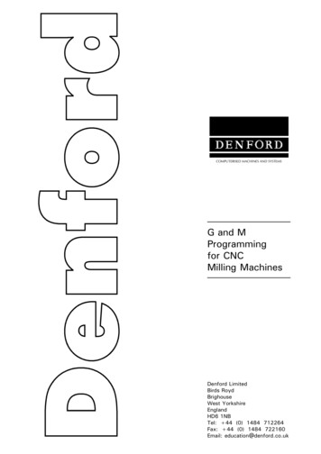
Software2.3 Main WindowOn launch of PlanetCNC TNG software Main Window will display.There are seven areas within the window. Each provides information or function concerningspecific aspects of G-Code program execution, purposes of illustration or displaying machines orcontrollers state. Position / State / Jogging panels.Program visualization/preview.G-Code panel.Manual data input (MDI) panel.Menus and toolbars.Status bar.31
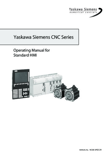
Software2.3.1Position/Status PanelPosition panel layout consists of position panel, statuspanel and jogging panel.2.3.1.1 Position PanelPosition panel uses 4 tabs: Work, Machine, Motors,Gcode.2.3.1.1.1WorkThis tab displays work or relative position coordinates ofmachine.2.3.1.1.2MachineThis tab displays machine or absolute position coordinates of machine.32
Software2.3.1.1.3MotorsThis tab displays motor position coordinates.2.3.1.1.4GCodeThis tab displays positions coordinates of selected g-code line.User can set new Work or Machine position value by double clicking on the axis value ofWork or Machine tab. To Value. insert filed will appear:33
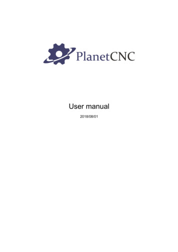
Software2.3.1.2 Status PanelStatus panel uses tabs for various parameter display.34
Software2.3.1.2.1Main TabMain tab displays machine speed parameters and active G-codes, M-codes and Other codes.Speed display:By clicking speed dial button, additional feed speed options appear:User can set new feed speed override value using buttons:Decrease: Decreases speed override value for 10%.Increase: Increases speed override value for 10%.Reset: Resets any speed override.By clicking spindle button, additional spindle speed options will appear:User can set new spindle speed override value using buttons:Decrease: Decreases speed override value for 10%.Increase: Increases speed override value for 10%.Reset: Resets any speed override.Regarding override please also read chapter: 2.8.3.23.3.35
SoftwareActive G-Codes:Displays all currently active G-codes.Active M-Codes:Displays all currently active M-codes.Other Codes:Displays all currently active G-codes such as F-word, S-word g-codes and current toolnumber.2.3.1.2.2IO TabIO tab displays status of controllers input and output pins.36
Software2.3.1.3 Jogging PanelJogging panel offers jog buttons to move machine to desired position.Jogging layout is hidden by default:by clicking cross-arrow button, jogging panel will appear:Mouse click hold on large arrow jog buttons to jog machine in desired direction. Machine will moveuntil the mouse button is released. Corner buttons allow diagonal or combined axis jogging.Smaller arrows, near the center of jog controls, perform a single step move per click.New jogging speed can be set by double clicking on the jogging speed value, Set Jog Speed insertfiled will appear:37
SoftwareIn settings (chapter 2.8.3.11), user can change jogging panel layout as also change hiddenbehavior to fixed(jogging panel is always displayed on main window):38
Software2.3.2ToolbarsEmergency stop:Executes immediate Emergency Stop (E-Stop)Open program:Loads a G-Code programStart execution:Start program executionStop execution:Stop program executionPause execution:Pause program executionTop View:Display G-Code program view from the topSide View:Display G-Code program view from the sideFront View:Display G-Code program view from the frontPerspective View:Display G-Code program using ‘Perspective’ viewZoom In:Zoom display in to view detailsZoom Out:Zoom display out to view a larger areaZoom Tool:Zoom display to the current tool positionZoom Extents:Zoom display to the G-Code program extentsMist:Activate / Deactivate Coolant MistFlood:Activate / Deactivate Coolant FloodSpindle:Activate / Deactivate Spindle39
SoftwareMove/To Zero:Moves the machine XY and Z axis to zero position.Move/Axis To Zero/XY:Moves the machine X and Y axis to zero position.Move/To G28:Moves machine to the absolute G28 position as set with Machine/Absolute Position/As G30.Move/ To G30:Moves machine to the absolute G30 position as set with Machine/Absolute Position/AsG30.Work Offset/To Zero:Sets working offset to zero.Work Position/Axis To Zero/XY:Sets the current XY position of machine as zero XY work position.Work Position/Axis To Zero/Z:Sets current Z position of machine as zero Z work position.Work Position/Measure:Measures Z working position at current machine position, using movable tool sensor.Tool Offset/Measure:Measures tool length using a fixed tool sensor.Home:Initiate automatic homing procedure.40
Software2.3.3Menu barMenu bar populates File, View, Program, Machine and Help menus.To activate specified menu, click on the menu bar item.41
Software2.3.4Manual data input (MDI) windowMDI window allows user of manual G-code input andexecution of MDI shortcuts.Example (manual G-code input):Typing G53 X0 Y0 Z10 will move machine to its absolute position of X0 Y0 Z10.The MDI window can also be used for execution of shortcuts using MDI codes(see chapter2.8.3.23.3 ).Example (MDI code):In settings, shortcut MDI code named Log was set forShow Log action.Typing /Log into MDI window will open Show Log dialog.Please note: Symbol “/” before MDI code needs to be used.Line break can be created with keyboard key combinationShift Enter. This way user can inputmulti-line g-code command:42
Software2.3.5G-Code panelG-code panel displays current program g-code lines.2.3.5.1 Vertical SliderAt the right side of G-code panel is vertical slider. Dragging sliderup or down user can navigate trough pages of current g-codeprogram.2.3.5.2 Position SliderAt the bottom of G-Code panel is position slider. Dragging sliderleft or right, user can navigate trough program lines and observesprogress of toolpath simulation in program visualization display.2.3.5.3 Additional G-code panel optionsRight mouse click on selected g-code line opens a dialog with additional options:43
Software2.3.5.3.1Start From Selected LineProgram will start at position of selected program g-code line.2.3.5.3.2Move/To Selected LineSee chapter 2.6.12.62.3.5.3.3Move To Selected Line XYSee chapter 2.6.12.72.3.5.3.4Move/Camera To Selected Line XYSee chapter 2.6.12.102.3.5.3.5Copy To ClipboardSee chapter 2.5.162.3.5.3.6Paste From ClipboardSee chapter 2.5.172.3.5.3.7Open.See chapter 2.3.22.3.5.3.8CloseSee chapter 2.3.144
Software2.3.6Program visualizationShows 3D display of g-code program.45
Software2.3.7Indication LightIn the bottom right corner of main window is connection light that indicates controllers statusconcerning license activation and connection with PlanetCNC TNG software.2.3.7.1 Connection light color description:Green light:Indicates that controller is updated to correct firmware version and controller is activated meaninglicense is found by software:Green light with X:Indicates that software does not find proper license for connected controller. Make sure that yourPlanetCNC TNG license is correctly imported.Orange light with X:Indicates that controllers firmware version is not correct.Gray light with X:Indicates no communication between controller and software. Click Machine/Controller/Reconnectand make sure that correct controller is set as Primary controller in settings.Red light with status bar:Indicates that software is processing motion commands and is sending them to controller.Runtime status bar:Displays job progress as remaining time of job runtime as also as progress bar.46
Software2.4 File menuFile menu offers a group of methods for opening, importing and exporting of machineprograms.Programs can be used for visualization, simulation, generating toolpath and can be in variousformats.Import features display user dialogues for entry of user parameters. Description of features isprovided below.G-Code can be exported using an option best suited to user requirement.‘Settings’ is where we configure and set machines main parameters.47
Software2.4.1CloseCloses program that is currently opened.2.4.2OpenOpens new program. Software will try to auto detect file format.Example: If you want to open .dxf file, TNG software will automatically recognize the DXF fileformat and launch DXF import dialog.2.4.3Recent filesDisplays a list of recently opened programs. Select file for open from a drop-down list.48
Software2.4.4Import G-codeOpens program in G-code form. G-code file can use different extensions. Usuallyextensions are: *.nc, *.tap, *.cnc, *.iso, *.gcode, *.ncf, *.txt.49
Software2.4.5Import DXF.and2.4.6Import PLT, HPGL.Imports program in DXF and PLT/HPGL format. Most software's for CAD drawing or vector imageshave option to save design in DXF format.These types of format usually contain vectors, that can be converted to toolpath. PlanetCNC TNGsoftware will automatically generate g-code program based on your imported DXF file.When using Import DXF feature, user dialog will be displayed. User has option to configureprogram parameters to suit his machining needs.50
Software2.4.6.1 UnitsYou can set units as Metric(mm) or Imperial (in) for your DXF design. You can fine tune your unitsusing Scale option.2.4.6.2 ScaleSets scale of your imported DXF design. This comes handy when you need your toolpath to be resized or some other units are used.E.g.: If you DXF design is drawn in centimeters (cm) then select Units as Metric and set Scale to10.51
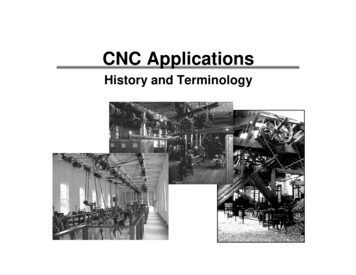
Software2.4.6.3 ExtentsExample:Let say we import DXF file of which we do not know its absolute XY 0,0 coordinates.Generated toolpath will be positioned accordingly, but not necessarily in a way that would suit us :Generated toolpath is positioned in relation to its absolute XY 0,0 coordinates (the way it wasdrawn). But what if we want that toolpath extents are aligned with working position XY0,0?52
SoftwareFor this purpose you can use one of five options under Extents:-Bottom left :-Top Left:-Center:-Bottom right:-Top right:53
SoftwareExample:Bottom Left:With this option enabled, toolpath XY0,0 point will be aligned with our working offset XY0,0:54
SoftwareCenter:With this option enabled, toolpath center point will be aligned with our working offset XY0,0:55
Software2.4.6.4 LoopsYou can set number of loops of your program. Each generated toolpath pass will be repeated forinserted value of loops.Example: If you insert Loop:3, pass will be repeated for 3 iterations.2.4.6.5 InterpolateIf your DXF file contains elements such as circles, arcs etc. you can interpolate these elementsinto short lines by enabling Interpolate option.2.4.6.6 Feed SpeedSets feed speed for generated toolpath. F-word g-code will be generated. Each feed move will beperformed at this speed.2.4.6.7 Plunge SpeedSet feed speed of plunge moves for generated toolpath. Each feed move in Z- direction (plunge)will be performed at this speed.2.4.6.8 Tool changeGenerated program will include tool change commands.Please note: If DXF file uses layers, each layer will represent different tool number in generatedprogram. Tn M6 and G43 Hn g-codes will be generated for specified tool.56
Software2.4.6.9 OutputsGenerated program will include M3/M5;M7,M8/M9 spindle and coolant g-code commands,depending on options selected.Please note: If DXF file uses layers then outputs will be turned ON at beginning and turned OFF atend of layers toolpath.Spindle:With this option enabled, generated program will include M3/M5 g-codes.If layers are used in DXF file, layers toolpath will include M3 g-code at start and M5 g-code at theend.If no layers are used in DXF design, spindle g-codes will be generated only at the beginning ofprogram and at the end.Flood:With this option enabled, generated program will include M7/M9 g-codes.If layers are used, layers toolpath will include M7 g-code at the start and M9 g-code at the end.If no layers are used, Flood g-codes will be generated only at the beginning of program and at theend.Mist:With this option enabled, generated program will include M8/M9 g-codes.If layers are used, layers toolpath will include M8 g-code at the start and M9 g-code at the end.If no layers are used, Mist g-codes will be generated only at the beginning of program and at theend.57
Software2.4.6.10Enable scriptsEnable Scripts provides means to personalize and achieve advanced g-code generation whenusing Import DXF feature.Automatically generated g-code of DXF Import feature is not necessarily within usersrequirements. User can tweak the DXF Import importation script to achieve desired results.2.4.6.11ModeYour DXF design can be in 2D or 3D. If 2D mode is selected, Height options will be enabled andyou will be able to configure height cutting parameters of generated toolpath.If 3D mode is enabled, Height options will be disabled since it is assumed that are already definedin original DXF (however, Safe Height option is available).3D mode also enables user to translate g-code from conventional XYZ plane to UVW, ZXY or YZKplane:XYZ- UVWWith this option selected, generated g-code program will translate XY coordinates to UVcoordinates. This feature is useful for foam cutters, where second tower uses UV coordinates forits motion.XYZ- ZXYWith this option selected, generated g-code program will be in ZX plane. XYZ coordinates fromDXF will be translated to ZXY.58
SoftwareXYZ- YZXWith this option selected, generated g-code program will be in YZ plane. XYZ coordinates fromDXF will be translated to YZX.2.4.6.12Height59
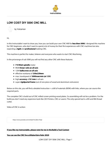
Software2.4.6.12.1Safe HeightWhen 2D mode is used then Height parameters can be set.Safe height is a safety feature which helps with prevention of machine crashing into obstacles thatmay interfere with machines toolpath. Obstacles could be screws, fixtures, vises etc.When machine is finished with cutting toolpath A, it will ascend to safe height and move to nextcutting location of toolpath B.With this option enabled, generated toolpath will include traverse moves performed at safe height.Toolpath without safe height:Toolpath with safe height:60
Software2.4.6.12.2Start HeightStart height is usually surface of workpiece material. To this height, machine will descend attraverse rate.2.4.6.12.3Step DownDepth of first cutting pass. Each new cutting pass will be deeper for this value. To this height,machine will descend at plunge rate.2.4.6.12.4Cut HeightDeepest cutting depth that machine will cut at.NOTE: Software will automatically calculate number of passes to achieve “Cut Height” depth at“Step Down” value per pass.Example:61
SoftwareLet's say we want to cutout a square out of a solid wooden block of thickness 30mm.We would like to cut in passes, with each pass being 4mm deeper than the previous one. Tosuccessfully cutout our square, deepest cut should be performed at 31mm.Set work position Z 0 is at surface of wooden block.Start Height 0Step Down -4Cut Height 31Bottom picture displays side view of generated toolpath based on parameter configurationdescribed above:62
Software2.4.6.13TabsTabs are used for holding element in place during cut.Enable:Enables tabs.Distance:Distance between two tabs.Size:Size of tabs.Example of toolpath with tabs enabled:63
Software2.4.6.14Tangent KnifeEnable:Enables C axis movement in direction of toolpath for use with tangential knives. Safe Height movesare generated if required.64
Software2.4.6.15Bottom - OffInserts OFF g-codes for Spindle, Flood, Mist (M5,M9), Delay and Pause at the end of cut beforemoving up to Safe HeightSpindle:Inserts OFF g-code for Spindle M5.Flood:Inserts OFF g-code for Flood M9.Mist:Inserts OFF g-code for Mist M9.Delay:Inserts Delay G04 P g-code.Pause:Inserts Pause M00 g-code.2.4.6.16Top OffInserts OFF g-codes for Spindle, Flood, Mist (M5,M9), Delay and Pause at the end of cut aftermoving up to Safe Height.Spindle:Inserts OFF g-code for Spindle M5.Flood:Inserts OFF g-code for Flood M9.Mist:Inserts OFF g-code for Mist M9.Delay:Inserts Delay G04 P g-codePause:Inserts Pause M00 g-code65
Software2.4.6.17Top OnInserts ON g-codes for Spindle, Flood, Mist (M3,M7,M8), Delay and Pause before cut, beforemoving down from Safe Height to cut (or pass) height.Spindle:Inserts ON g-code for Spindle M3.Flood:Inserts ON g-code for Flood M7.Mist:Inserts ON g-code for Mist M8.Delay:Inserts Delay G04 P g-codePause:Inserts Pause M00 g-code2.4.6.18Bottom OnInserts ON g-codes for Spindle, Flood, Mist (M3,M7,M8), Delay and Pause before cut, after movingdown from Safe Height to cut (or pass) height.Spindle:Inserts ON g-code for Spindle M3.Flood:Inserts ON g-code for Flood M7.Mist:Inserts ON g-code for Mist M8.Delay:Inserts Delay G04 P g-codePause:Inserts Pause M00 g-code66
Software2.4.7Import GerberImports Gerber file. Gerber files are generated with software for design of printed circuitboards(PCB's). With gerber files you can also mill printed circuit boards with your CNC machine.67
Software2.4.7.1 Feed SpeedSets feed speed for generated toolpath. F-word g-code will be generated. Each G01 move will beperformed at this speed.2.4.7.2 Plunge SpeedSets feed speed of plunge moves for generated toolpath. Each G01 move in Z- direction will beperformed at this speed.2.4.7.3 Safe HeightSafe height is a safety feature which helps with prevention of machine crashing into obstacles thatmay interfere with machines toolpath. Obstacles could be screws, fixtures, vises etc.When machine is finished with cutting toolpath A, it will ascend to safe height and move to nextcutting location of toolpath B.With this option enabled, generated toolpath will include traverse moves performed at safe height.2.4.7.4 Start HeightStart height is usually surface of workpiece material. To this height, machine will descend attraverse rate.2.4.7.5 Tool changeEnables tool change for: Mark Pads, Cutting Path, Drill Pads or Clear Copper options.Please note: When configuring options Mark Pads, Cutting Path, Drill Pads or Clear Copper youneed to enable them and define tool number.68
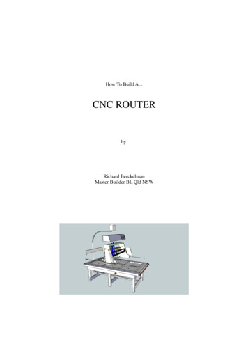
Software2.4.7.6 MirrorMirrors program in XY.Normal toolpath:69
SoftwareMirrored toolpath:2.4.7.7 Size XX coordinate approximate dimension of PCB board. This comes very useful when drilling holes ofPCB using NC drill file. Make sure that same value is used with NC drill import.2.4.7.8 Size YY coordinate approximate dimension of PCB board.70
Software2.4.7.9 OutputsGenerated program will include M3/M5;M7,M8/M9 g-code commands, depending on optionsselected.Spindle:With this option enabled, generated program will include M3/M5 g-codes. If tool change is enabledM3/M5 g-codes will be generated for each toolchange.Flood:With this option enabled, generated program will include M7/M9 g-codes. If tool change is enabledM7/M9 g-codes will be generated for each toolchange.Mist:With this option enabled, generated program will include M8/M9 g-codes. If tool change is enabledM8/M9 g-codes will be generated for each toolchange.71
Software2.4.7.10UseGerber files can contain different elements such as polygons, tracks, pads and holes.You can select which element(s) will be converted to toolpath.Polygons:Use 'Polygons' in toolpath calculation. Only polygons will be visible.Tracks:Use 'Tracks' in toolpath calculation. Only tracks will be visible.Pads:Use 'Pads' in toolpath calculation. Only pads will be visible.Holes:Use 'holes' in toolpath calculation. Only holes will be visible.2.4.7.11Enable ScriptsEnable Scripts provides means to personalize and achieve advanced g-code generation whenusing Import Gerber feature.Automatically generated g-code of Import Gerber feature is not necessarily within usersrequirements. User can tweak the Import Gerber importation script to achieve desired results.72
Software2.4.7.12Mark PadsYou can mark selected pad shapes to ease manual drilling later. Software will recognize shapes:Circle, Oval, Rectangle, Polygon or Other(custom).Circle:Use circle pads for marking. Only circled pads will be marked.Rectangle:Use circle pads for marking. Only circled pads will be marked.Oval:Use oval pads for marking. Only oval pads will be marked.Polygon:Use polygon pads for marking. Only polygon pads will be marked.Other:Use other(custom) pads for marking. Only other(custom) pads will be marked.2.4.7.13Cut HeightDepth of marking point.2.4.7.14PauseInsert 'Pause' (M00) G-Code before marking pads.2.4.7.15ToolNumber of tool used for marking pads. If tool change is enabled, tool with this number will be used.73
Software2.4.7.16Cutting PathIsolation:Enable to mill electrical isolation toolpath.Centerline:Enable to mill center line (for example silkscreen or cutout).2.4.7.17PassesNumber of milling passes of electrical isolation toolpath. Each milling pass is distanced fromprevious one for value of tool radius (tool used for Cutting Path).2.4.7.18Cut HeightDepth of milling.2.4.7.19PauseInsert 'Pause' (M00) G-Code before milling electrical isolation toolpath.2.4.7.20ToolNumber of tool used for milling electrical isolation toolpath. If tool change is enabled, tool with thisnumber will be used.2.4.7.21DiameterDiameter of tool used for milling electrical isolation toolpath. Radius of this value is used forPasses toolpath.74
Software2.4.7.22Drill PadsYou can drill selected pad shapes. Software will recognize shapes: Circle, Oval, Rectangle,Polygon or Other(custom).You might want to drill hole on circled pad for trou
Software 2 Software 2.1 Overview PlanetCNC TNG software is designed to fully exploit the advanced features of controller hardware. At the same time the software remains user friendly. Even those new to CNC machining can employ advanced functions with ease. Configuration options allow for maximum flexibility, integration and customization.