Transcription
Yaskawa Siemens CNC SeriesOperating Manual forStandard HMIMANUAL No. NCSIE-SP02-24
Yaskawa Siemens Numerical Controls Corp. has been merged to Siemens K.K. andSiemens Japan K.K. as of August, 2010 respectively. "Yaskawa Siemens NumericalControls Corp." in this manual should therefore be understood as "Siemens Japan K.K."This manual is intended for both of Yaskawa Siemens 840DI and Yaskawa Siemens 830DI.In this manual, the functional differences of these two models are not taken into account inits description, thus please refer to the catalog (MANUAL No.: NCKAE-PS41-01) foravailable basic functions and possible optional functions of each model.
NCSIE-SP02-24.book0iii �9時37分006.05Safety-related symbol marksThe following symbol marks are used in this manual to draw special attention to safety information.The information next to these symbol marks is important for safety andthus must always be followed.Indicates activities that could result in a dangerous condition, includingdeath and serious injury, if done wrongly.Symbolis used in labels attached to the product.Indicates activities that could result in a dangerous condition, includingmajor and minor injury, or in damage to objects, if done wrongly.It is noted that those activities as indicated by thesymbolmark could even result in death or serious injury if done wrongly in aworst-case situation.Indicates what you must not do. For example, thethat you must not make or use a fire here.!mark meansIndicates what you must do unconditionally. For example, theground mark means that you must always ground the object you areworking with.iii
NCSIE-SP02-24.bookiv �9時37分006.050Outline of this ManualThis manual describes cautionary items and operation procedures onstandard HMI of Yaskawa Siemens CNC series that is CNC for machinetools.Extensions or changes made by the machine tool manufactures aredocumented by the machine tool manufactures.This manual is intended for use by operators of machine control paneland operator panel of machine tools controlled by the Yaskawa Siemens CNC system.This manual describes the functionality of Yaskawa Siemens 840DI andYaskawa Siemens 830DI, however does not describe differences in thefunctions between both models.Standard and optional functions are provided in each model.Please read catalogue (document no.:NCKAE-PS41-01)TrademarksYaskawa Siemens is a brand made by Yaskawa Siemens NC.SINUMERIK is a brand made by Siemens AG.Any other designations used in this publication could be brands which,if being used by third parties of their purposes, could impair the rights ofthe owners.Related ManualsRelated manuals are listed below, which you should read as necessaryalong with this manual.Read all related manuals to grasp the specifications.Manual NameivManual NumberYaskawa Siemens CNC Series (Catalog)NCKAE-PS41-01Yaskawa Siemens CNC Series Operating ManualNCSIE-SP02-04Yaskawa Siemens CNC Series Operating Manual forJ-OperationNCSIE-SP02-23Yaskawa Siemens CNC Series Maintenance ManualNCSIE-SP02-10Yaskawa Siemens CNC Series Maintenance ManualServiceman HandbookNCSIE-SP02-19Yaskawa Siemens CNC Series Programming Manualfor Machining CenterNCSIE-SP02-20Yaskawa Siemens CNC Series Programming Manualfor LatheNCSIE-SP02-21Yaskawa Siemens CNC Series Operating Manualfor Machining CenterNCSIE-SP02-25
NCSIE-SP02-24.book0v �9時37分006.05CautionsThis manual describes some optional functions too but some of thesemay not be available with your Yaskawa Siemens CNC. To determinethe optional functions installed in your NC, refer to the specification document or manuals published by the machine tool builders.We has made every effort to describe individual functions and their relationships to other functions as accurately as possible. However, thereare many things that cannot or must not be performed and it is not possible to describe all of these. Accordingly, readers are requested to understand that unless it is specifically stated that something can beperformed, it should be assumed that it cannot be performed.Also bear in mind that the performance and functions of an NC machinetool are not determined solely by the NC unit. The entire control systemconsists of the mechanical system, the machine operation panel andother machine related equipment in addition to the NC. Therefore, readthe manuals published by the machine tool builder for detailed information relating to the machine.Safety precautionsListed below are important safety precautions that you must always follow when using the product, Read and fully understand this manual andother related manuals before attempting to install, operate, maintain, orservice the product. The safety precautions and the knowledge of theproduct are indispensable for the safety of yourself and the product.OperatingWarning Do not touch live units or terminals.Otherwise electric shock or malfunction could result.Do not touch any current-carrying parts even if you have shut offpower to them, until at least 5 minutes have passed (to let any residuaI change go out).Otherwise electric shock or malfunction could result.Take care not to damage, pull on, or pinch the cables.Otherwise electric shock could result.Do not touch any rotating parts before you shut off power to them.Otherwise injury could result.Never attempt to modify the product.Otherwise electric shock, a fire, or damage could result.Close the upper and lower covers before switching on the inputpower.Otherwise electric shock could result.Provide an additional emergency stop button outside the product.This is a necessary safety precaution.v
NCSIE-SP02-24.bookvi �9時37分006.050Caution MaintainingEnsure that the environmental requirements are fully met.A fire, electric shock, or malfunction could result if the product wereoperated in excessively hot, humid, dusty, corrosive, vibration-,orshock-ridden conditions.The environmental requirements are these:- The atmosphere must be free of corrosive gas or vapor.- There must be no risk of being splashed with machining oil ororganic solvent.- The relative humidity must be between10 and 90% with no dew.- The ambient temperature around the control panes must be between 5 and 30 C. The control panels must be protected fromfreezing, direct sunlight, heat sources, or the elements.- Floor vibration must not be more than 4.9m/s2.Take care so that no wire chips or other foreign matter would enterthe product.Otherwise a fire, damage, or malfunction could result.When using the programming functions, always follow the instructions given in the relevant manuals.Otherwise injury or malfunction could result.Warning Do not touch the terminals of the inverters or converters, as someof them are at high voltage and very dangerous.Otherwise electric shock could result.Do not leave the upper or lower cover open when the panel is energized.Always turn off the circuit breaker before opening the covers.Otherwise electric shock could result.Confirm that the main power and the control power are switched offand the CHARGE lamp is not before starting maintenance work.Be aware that capacitors can have a high voltage charge for a whileeven after the circuit breaker is switched off.Only qualified personnel may perform maintenance or service work.Otherwise electric shock could result.Caution viWhen handling the control PC boards, take necessary measure toprevent their CMOS ICs from being damaged from electrostatic discharge.Do not touch the CMOS ICs. Otherwise they could be damaged.Never attempt to change wiring connections, or engage or disengage connectors while they are energized.Otherwise injury could result.
NCSIE-SP02-24.book0vii �9時37分006.05OthersWarning General notesNever attempt to modify the product.Otherwise electric shock or injury could result.Notes on the usage of this manual Illustrations and drawings in this manual may show parts with theircover or safety shield removed so that inside details can be seen.Regardless of the drawings, the products must always be operatedaccording to the manual with all the covers and shields installed inplace.Illustrations and photos in this manual represent typical configurations, and may not exactly represent the products delivered.This manual is subject to change to reflect modification or specification change to the product or to make it easier to read. An updateddocument No. means a new version of this manual.If you need additional copies of this manual to replace damaged orlost ones or otherwise, please order from the nearest sales office indicated on the back cover referring to the document No. printed onthe front cover of this manual.If the nameplate on the products is defaced or damaged, order anew one from your dealer or the nearest sales office indicated onthe back cover of this manual.Yaskawa Siemens would not guarantee the quality of the productmodified by the customer. Yaskawa Siemens is not responsible forany injury or damage due to the product modified by the customer.Warning LabelsWarning labels are attached to the product to draw special attention. Always follow the instructions. The locations and meanings of the warninglabels are as follows: Warning label 1WARNINGRisk of electric shock.5Read manual before installing.Wait 5 minutes for capacitor discharge afterdisconnecting power supply.Risk of electric shock Read manual before installing. Wait 5 minutes for capacitor discharge after disconnecting powersupply.vii
NCSIE-SP02-24.bookviii �9時37分006.05 0Warning label 2Risk of electric shock Do not touch the terminals while theproduct is switched on or for 5 minutes after the product is switchedoff.SERVOPACKPosition of warning label 1Position of warning label 1 Warning markingGround the unit by connecting a grounding wire tothis grounding terminal.SERVOPACKPosition of warning label 1Special symbolsThe following special symbols and keywords have been used in thisdocumentation.Machine ManufacturerviiiFor safety reasons, some of the functions are protected from access byunauthorized persons. The machine manufacturer can influence ormodify the described functions. Please follow the instructions of the machine manufacturer.
NCSIE-SP02-24.book0ix 午前9時37分0ContentsSafety-related symbol marks . . . . . . . . . . . . . . . . . . . . . . . . . . . . . . . . . . . . . . . . . . . . . . . . . . . . . . . . . . . iiiOutline of this Manual . . . . . . . . . . . . . . . . . . . . . . . . . . . . . . . . . . . . . . . . . . . . . . . . . . . . . . . . . . . . . . . . ivTrademarks . . . . . . . . . . . . . . . . . . . . . . . . . . . . . . . . . . . . . . . . . . . . . . . . . . . . . . . . . . . . . . . . . . . . . . . . ivRelated Manuals . . . . . . . . . . . . . . . . . . . . . . . . . . . . . . . . . . . . . . . . . . . . . . . . . . . . . . . . . . . . . . . . . . . . ivCautions . . . . . . . . . . . . . . . . . . . . . . . . . . . . . . . . . . . . . . . . . . . . . . . . . . . . . . . . . . . . . . . . . . . . . . . . . . . vSafety precautions . . . . . . . . . . . . . . . . . . . . . . . . . . . . . . . . . . . . . . . . . . . . . . . . . . . . . . . . . . . . . . . . . . . vWarning Labels . . . . . . . . . . . . . . . . . . . . . . . . . . . . . . . . . . . . . . . . . . . . . . . . . . . . . . . . . . . . . . . . . . . . viiSpecial symbols . . . . . . . . . . . . . . . . . . . . . . . . . . . . . . . . . . . . . . . . . . . . . . . . . . . . . . . . . . . . . . . . . . . . viii1 Introduction . . . . . . . . . . . . . . . . . . . . . . . . . . . . . . . . . . . . . . . . . . . . . . . . . . . . 121.1 How to read this document . . . . . . . . . . . . . . . . . . . . . . . . . . . . . . . . . . . . . . . . . . . . . . . . . . . 121.2 Scope of functions . . . . . . . . . . . . . . . . . . . . . . . . . . . . . . . . . . . . . . . . . . . . . . . . . . . . . . . . . 132 Operator Panel . . . . . . . . . . . . . . . . . . . . . . . . . . . . . . . . . . . . . . . . . . . . . . . . . 142.1 View of Operator Panel . . . . . . . . . . . . . . . . . . . . . . . . . . . . . . . . . . . . . . . . . . . . . . . . . . . . . 142.2 Arrangement of Operator Panel keys . . . . . . . . . . . . . . . . . . . . . . . . . . . . . . . . . . . . . . . . . . . 152.2.1 ABCD type keyboard . . . . . . . . . . . . . . . . . . . . . . . . . . . . . . . . . . . . . . . . . . . . . . . . . . . 152.2.2 QWERTY type keyboard . . . . . . . . . . . . . . . . . . . . . . . . . . . . . . . . . . . . . . . . . . . . . . . . 152.3 Operator Panel keys . . . . . . . . . . . . . . . . . . . . . . . . . . . . . . . . . . . . . . . . . . . . . . . . . . . . . . . . 162.3.1 Hot keys . . . . . . . . . . . . . . . . . . . . . . . . . . . . . . . . . . . . . . . . . . . . . . . . . . . . . . . . . . . . . 162.3.2 Reset key . . . . . . . . . . . . . . . . . . . . . . . . . . . . . . . . . . . . . . . . . . . . . . . . . . . . . . . . . . . . 163 Machine Control Panel OP032S. . . . . . . . . . . . . . . . . . . . . . . . . . . . . . . . . . . . 173.1 View of Machine Control Panel OP032S . . . . . . . . . . . . . . . . . . . . . . . . . . . . . . . . . . . . . . . . 173.2 Keys on OP032S Machine Control Panel. . . . . . . . . . . . . . . . . . . . . . . . . . . . . . . . . . . . . . . . 174 Macro variable data screen . . . . . . . . . . . . . . . . . . . . . . . . . . . . . . . . . . . . . . . 184.1 Basic display. . . . . . . . . . . . . . . . . . . . . . . . . . . . . . . . . . . . . . . . . . . . . . . . . . . . . . . . . . . . . . 184.2 Displaying/ finding macro variables . . . . . . . . . . . . . . . . . . . . . . . . . . . . . . . . . . . . . . . . . . . . 194.3 Modifying macro variable . . . . . . . . . . . . . . . . . . . . . . . . . . . . . . . . . . . . . . . . . . . . . . . . . . . . 194.4 Set empty . . . . . . . . . . . . . . . . . . . . . . . . . . . . . . . . . . . . . . . . . . . . . . . . . . . . . . . . . . . . . . . . 204.4.1 Empty . . . . . . . . . . . . . . . . . . . . . . . . . . . . . . . . . . . . . . . . . . . . . . . . . . . . . . . . . . . . . . . 204.4.2 Set macro variable number area for empty . . . . . . . . . . . . . . . . . . . . . . . . . . . . . . . . . . 204.4.3 Set all empty. . . . . . . . . . . . . . . . . . . . . . . . . . . . . . . . . . . . . . . . . . . . . . . . . . . . . . . . . . 21ix
NCSIE-SP02-24.book0x �9時37分06.0505 Common Operating Screen . . . . . . . . . . . . . . . . . . . . . . . . . . . . . . . . . . . . . . . 225.1 All position screen. . . . . . . . . . . . . . . . . . . . . . . . . . . . . . . . . . . . . . . . . . . . . . . . . . . . . . . . . . 225.1.1 Basic screen . . . . . . . . . . . . . . . . . . . . . . . . . . . . . . . . . . . . . . . . . . . . . . . . . . . . . . . . . . 225.1.2 Relative coordinate system setting . . . . . . . . . . . . . . . . . . . . . . . . . . . . . . . . . . . . . . . . . 235.1.3 Channel switchover . . . . . . . . . . . . . . . . . . . . . . . . . . . . . . . . . . . . . . . . . . . . . . . . . . . . 235.2 Run time display screen . . . . . . . . . . . . . . . . . . . . . . . . . . . . . . . . . . . . . . . . . . . . . . . . . . . . . 245.2.1 Basic display. . . . . . . . . . . . . . . . . . . . . . . . . . . . . . . . . . . . . . . . . . . . . . . . . . . . . . . . . . 245.2.2 Count condition setting . . . . . . . . . . . . . . . . . . . . . . . . . . . . . . . . . . . . . . . . . . . . . . . . . . 255.2.3 Timer clear . . . . . . . . . . . . . . . . . . . . . . . . . . . . . . . . . . . . . . . . . . . . . . . . . . . . . . . . . . . 255.2.4 Channel switchover . . . . . . . . . . . . . . . . . . . . . . . . . . . . . . . . . . . . . . . . . . . . . . . . . . . . 266 Displaying the version information screen. . . . . . . . . . . . . . . . . . . . . . . . . . . 276.1 Basic display . . . . . . . . . . . . . . . . . . . . . . . . . . . . . . . . . . . . . . . . . . . . . . . . . . . . . . . . . . . . . . 276.2 Operation . . . . . . . . . . . . . . . . . . . . . . . . . . . . . . . . . . . . . . . . . . . . . . . . . . . . . . . . . . . . . . . . 287 Activation of STEP7 . . . . . . . . . . . . . . . . . . . . . . . . . . . . . . . . . . . . . . . . . . . . . 298 Tables . . . . . . . . . . . . . . . . . . . . . . . . . . . . . . . . . . . . . . . . . . . . . . . . . . . . . . . . . 308.1 Comparison table of Operator Panel keys . . . . . . . . . . . . . . . . . . . . . . . . . . . . . . . . . . . . . . . 308.2 Comparison table of Machine Control Panel keys . . . . . . . . . . . . . . . . . . . . . . . . . . . . . . . . . 318.3 Comparison for references . . . . . . . . . . . . . . . . . . . . . . . . . . . . . . . . . . . . . . . . . . . . . . . . . . . 31x
NCSIE-SP02-24.book112 �9時37分1 Introduction06.051.1 How to read this document1Introduction1.1How to read this document1The standard HMI for the Yaskawa Siemens CNC Series is built upbased on HMI Advanced for SINUMERIK 840D. Therefore, You can refer the following document in connection with the most of all operationson standard HMI for the Yaskawa Siemens CNC Series.Reference : SINUMERIK 840D/840Di/810DOperator’s Guide HMI AdvancedThis manual describes the characteristic operation of Yaskawa Siemens CNC Series compared with Operator’s Guide HMI Advanced.When you use the Operator’s Guide HMI Advanced for operating theYaskawa Siemens CNC Series, please replace the words acording tothe following table.words12replacementSINUMERIK 840DSINUMERIK 840Di840D840DiCorresponded to Yaskawa Siemens CNCSeriessoftware versionSW . Corresponded to the latest description forYaskawa Siemens CNC Series.SINUMERIK documentationOrder No. of documentReferencesConcerning the documents described in Operator’s Guide HMI Advanced, the all mostof SINUMERIK documents can be used forYaskawa Siemens CNC Series too. For further information, please refer to Section 8.3“Comparison for the References”.OP010OP010SOP010COP012OP015Only the OP010FS is used as operator component for Yaskawa Siemens CNC Series.
NCSIE-SP02-24.book11.213 �9時37分06.051 Introduction1.2 Scope of functions1Scope of functionsThe following functions and relating operations are not available forYaskawa Siemens CNC Series. Punching and NibblingSafety IntegratedNC cardUpgradeService driveDisplay of operating mode keys on vertical soft key bar by pressing the“Area switchover” keyThe toggle of operation area by pressing the “Area switchover” key twiceSINUMERIK 810DSINUMERIK 840DESINUMERIK 840DiESINUMERIK 810DE13
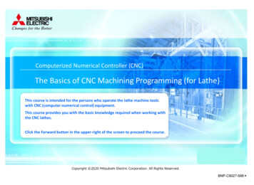
NCSIE-SP02-24.book2214 �9時37分2 Operator Panel06.052.1 View of Operator Panel2Operator PanelOP010FS is used for Yaskawa Siemens CNC Series. Beside there aretwo type of the keyboard for OP010FS, i.e. QWERTY type and ABCDtype, concerning arrangement and illustration of each key. For differences between these keyboards, please refer to Section 8.1 “Comparison table for keys”.The view of each Operator Panel can be shown below.2.1View of Operator PanelThe complete figure of OP010FS operator panel is shown below.14
NCSIE-SP02-24.book15 ��9時37分06.052 Operator Panel2.2 Arrangement of Operator Panel keys2.2Arrangement of Operator Panel keys2.2.1ABCD type keyboard2.2.2QWERTY type keyboard215
NCSIE-SP02-24.book216 �9時37分2 Operator Panel06.052.3 Operator Panel keys2.3Operator Panel keys2.3.1Hot keys2The following Hot Keys are available for Yaskawa Siemens CNC Series.Maint.%Run2.3.2By pressing this key, the last opened screen in Start-up Operating Areacan be displayed.By pressing this key, the last opened screen in Machine Operating Areacan be displayed.Reset keyThis key is on ABCD type keyboard.ResetWhen you press the "Reset" key: processing of the current parts program is aborted, signals from the monitoring function are cleared (except for alarmssignaling POWER ON, NC Start and Acknowledge alarm), the channel is switched to the "Reset" state, i.e.- the NC control remains synchronized with the machine,- the control is in the initial state and ready for another programrun.(See also /FB/, K1, Description of Functions Mode Group,Channel, Program Operation Mode)Reset key will work only, if machine manufacturer has implemented thefunction internally via the PLC interface.Please read the manufacturer’s instructions.16
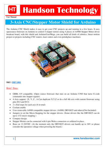
NCSIE-SP02-24.book3317 �9時37分06.053 Machine Control Panel OP032S3.1 View of Machine Control Panel OP032S3Machine Control Panel OP032SMachine Control Panel OP032S can be used for Yaskawa SiemensCNC Series.There are some different keys between OP032S and 19" Machine Control Panel described in Operator's Guide HMI Advanced. For more detailinformation about these differences, please refer to Section 8.2 “Comparison table of Machine Control Panel keys”.3.1View of Machine Control Panel OP032SThe view of Machine Control Panel OP032S is shown below.3.2Keys on OP032S Machine Control PanelThe following keys are available on OP032S Machine Control Panel.Start Spindle left turn ( CCW rotation )Spindle LeftStart Spindle right turn ( CW rotation )Spindle RightSpindle Dec.Spindle Inc.100%Machine ManufacturerThe Spindle override for the program spindle speed can be increasedor decreased.The Spindle override can be set to 100%.Above keys are assigned by Machine Manufacturer. Please refer toManufacturer's documents for the functionality of these keys.17
NCSIE-SP02-24.book4418 �9時37分4 Macro variable data screen06.054.1 Basic display4Macro variable data screenDisplaying simultaneously, editing and searching for macro variablescan be performed in Macro variable data screen.Macro variable screen is positioned in Parameter operating area forTurning system and in Common operating area for Machining system.4.1Basic displayNumber of variables in Macro variable screen is 26. (as 2 column 13lines.)"INS" is displayed in insert mode at the bottom right hand corner in thewindow."EDT" is displayed in entering values at the bottom right hand corner inthe window.You can specify three or eight digits for decimal fraction.If you select 3 digits for decimal fraction and integer values become over9 digits, display format is changed to [x.xxE xx]18
NCSIE-SP02-24.book44.219 �9時37分06.054 Macro variable data screen4.2 Displaying/ finding macro variables4Displaying/ finding macro variablesCommonorParameterMacro variables are nSwichingYou can select required kinds of macro variables.You can specify three or eight digits for decimal fraction.This soft key searches macro variable number which are displayed currently on the screen.SearchA dialog box is opened as indicated below.If you enter a number of macro variable and press the "OK" soft key.Thesearch run is started. and search result is displayed.OKYou can cancel the search run.Abort4.3Modifying macro variableThe macro variables that you want to modify can be selected by cursorkey "Up", "Down", "Left", "Right" and page key "PageUp", "PageDown".PageUpINSERTPageDownYou can alter either overwrite mode or insert mode with "insert" key.(default mode is overwrite mode.)Enter the value data and confirm your data with "input" key.INPUTNotes:Cursor key is deactivated while inputting the data and confirming thevalue in the EDIT mode.Overwrite mode is automatically switched when you press the cursorkey in insert mode with the exception of EDIT mode.19
NCSIE-SP02-24.book44.420 �9時37分4 Macro variable data screen06.054.4 Set empty4Set emptyMacro variables can be set to empty. Three different soft key are provided for setting empty.4.4.1EmptyEmpty4.4.2Macro variable on cursor can be set to empty. Variable data are displayed in blank.Set macro variable number area for emptyEmptyAreaMacro variable number in the specified area can be set to empty.A dialog box appears as indicated below when you select this soft key.OKMacro variable number is set to empty when you select "OK" soft keyafter entering the range of macro variable number.While the macro variable number is set to empty, message is displayedas follow.[n-m empty treatment is done. Wait for a while please.]NotesIf value in the "Form Y [ ]"column is lager than value in the "To Y [ ],i.e "Form Y [ ]" "To Y [ ]", warning message is displayed in a dialogbox.Abort20You can cancel execution of setting.
NCSIE-SP02-24.book21 �午前9時37分06.054 Macro variable data screen4.4 Set empty4Set all emptyAll macro variable numbers which are displayed currently on the screencan be set to empty.EmptyAllOKAbortA dialog box to confirm appears as indicated below, when you selectthis soft key.Macro variable number is set to empty when you select "OK" soft key.While the macro variable number is set to empty, message is displayedas follow.[All empty treatment is done. Wait for a while please.]You can cancel execution of setting.21
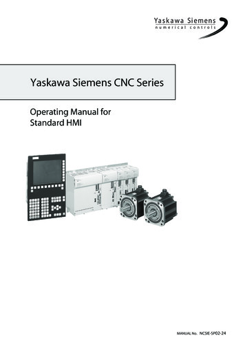
NCSIE-SP02-24.book5522 �9時37分5 Common Operating Screen06.055.1 All position screen5Common Operating ScreenMaint.Common5.1All position screen5.1.1Basic screenCommonAllpositionCommon operating area is provided for Yaskawa Siemens CNC.Two different screens in common operating area are as follows. All position screen to display the five different types of position data. Run time display screen to display five different types of timer relating to run operation.Select soft key "All Position" in common operating area.Five different types of position data (work coordinate system, relativecoordinate system, error pulse (positional deviation), distance to Go,machine coordinate system) are display on the screen.The column of Channel name, “ Channel1 ” in above example, and thevertical soft keys of “ Channel ”, “ Channel - ” and “ Direct Selection ”are displayed only when multiple channels are activated.22
NCSIE-SP02-24.book23 �午前9時37分06.055 Common Operating Screen5.1 All position screen5Relative coordinate system settingThe Relative coordinate system can be shifted on all position screen.By pressing the " Set Value " softkey, the cursor is displayed on the relative position of 1st axis with setting mode.SetvalueThe target axis can be selected by cursor up/down key.Enter a value and press the " Input " key, then the relative position ischanged.INPUTPush the “ Set Value ” softkey, then setting mode is terminated.SetvalueNotesThe offset for relative coordinate system is calculated by the formula described below.Offset Value entered - Setpoint on relative coordinate systembefore setting5.1.3Channel switchoverIf several channels are in use, it is possible to switch to the other channel by means of the soft keys in the vertical menu.ChannelChannel-Each soft key switches to next channel or previous channel.Channel name for intended field changes to another channel name.Position cursor on channel name column by pressing "Direct selection"soft key. Channel can be selected directly by using " UP" and "Down"cursor keys.DirectselectionOKAbortConfirm with "OK".Selection is canceled with "Abort" soft key.23
NCSIE-SP02-24.book524 �9時37分5 Common Operating Screen06.055.2 Run time display screen5.2Run time display screen5.2.1Basic display5Basic displayCommonSelect soft key "Run Time" in common operating area.Run Time"Channel name column", "Channel ","Channel -"and" Direct selection"display are only valid when several channels are in use.Five different types of timer are displayed as follows.You can set a machine data to determine whether screen display is enabled or disabled, and count conditions.Setup TimerTotal time since the last "booting of the CNC with the default values".Power On TimerTime since last controller power up.When the control system boots, the timer is automatically reset to zero.Operating TimerThe runtimes of all programs between NC start and program end/resetare added.The timer is set to zero with each booting of the control system.You can set a machine data MD27860:PROCESSTIMER MODE to determine whether screen display is enabled or disabled.MD27860 Bit0 0: Disable Operating TimerBit0 1: Enable Operating Timer24
NCSIE-SP02-24.book25 ��9時37分06.055 Common Operating Screen5.2 Run time display screen5Cycle timerThe runtime between NC start and program end/reset is measured inthe selected NC program.The timer is set to zero at program end.Starting a new NC program deletes the timer after reset operation.You can set a machine data MD27860:PROCESSTIMER MODE to determine whether screen display is enabled or disabled.MD27860 Bit1 0: Disable Cycle TimerBit1 1: Enable Cycle TimerCutting TimerThe runtime of the path axes is measured between NC start and program end/reset in all NC programs with the tool active.You can set a machine data MD27860:PROCESSTIMER MODE to determine whether screen display is enabled or disabled.MD27860 Bit2 0: Disable Cutting TimerBit2 1: Enable Cutting Timer5.2.2Count condition settingYou can set a machine data MD27860:PPOCESSTIMER MODE to determine whether count condition for" Operating timer" or "Cycle timer".MD27860 Bit4 0: Disable count timer in Dryrun modeBit4 1: Enable count timer in Dryrun modeMD27860 Bit5 0: Disable count timer in Program test modeBit5 1: Enable count timer in Program test modeNote: MD27860 can be written by means of protection level 3 to 7.5.2.3Timer clearEach timer can be set to zero by pressing "Timer Clear" soft key.TimerClear"Zero clear mode" is selected by pressing "Timer Clear".and the intended timer field display changes to active color.The vertical soft key bar also changes. and then the intended timer canbe selected by using UP and DOWN cursor keys.ClearBackAfter that, the selected timer data is cleared when the "Clear" soft key.Exit the "zero clear mode."Note: "Setup timer Clear" operating can be written by means of protection level 1.25
NCSIE-SP02-24.book26 ページ2005年6月1日55 C
Yaskawa Siemens CNC Series Programming Manual for Machining Center NCSIE-SP02-20 Yaskawa Siemens CNC Series Programming Manual for Lathe NCSIE-SP02-21 Yaskawa Siemens CNC Series Operating Manual for Machining Center NCSIE-SP