Transcription
How To Build A.CNC ROUTERbyRichard BerckelmanMaster Builder BL Qld NSW
Contents1.2.3.4.5.CNC basicsConstructionLinear MotionElectronicsSoftwareWhat is a CNC machine? (wikipedia)Numerical control (NC) refers to the automation of machine tools that are operated by abstractlyprogrammed commands encoded on a storage medium, as opposed to manually controlled viahandwheels or levers, or mechanically automated via cams alone. The first NC machines were builtin the 1940s and 1950s, based on existing tools that were modified with motors that moved thecontrols to follow points fed into the system on punched tape. These early servomechanisms wererapidly augmented with analog and digital computers, creating the modern computer numericalcontrol (CNC) machine tools that have revolutionized the manufacturing process.In modern CNC systems, end-to-end component design is highly automated using computer-aided design(CAD) and computer-aided manufacturing (CAM) programs. The programs produce a computer file that isinterpreted to extract the commands needed to operate a particular machine via a postprocessor, andthen loaded into the CNC machines for production. Since any particular component might require the useof a number of different tools-drills, saws, etc., modern machines often combine multiple tools into asingle "cell". In other cases, a number of different machines are used with an external controller andhuman or robotic operators that move the component from machine to machine. In either case, thecomplex series of steps needed to produce any part is highly automated and produces a part that closelymatches the original CAD design.CNC BASICSA CNC machine is probably the most useful tool a hobbyist can own, but the price for a CNC machine onthe market is way more than the average hobbyist is willing to spend. Build your own CNC explains how tobuild, program and manufacture your own products on your own machine.There are 3 steps to the project, Construction, Software, Manufacture.Firstly the Construction.
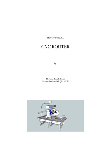
LINEAR MOTIONA CNC machine has three axis. The X, Y and Z. These represent the worktable. The x axis is the movementin the direction of the length of the table. The Y axis is width and the Z is vertical movement. When a CNCmachine works the computer instructs the cutting bit to move in all 3 axis.Our plan uses V shaped rollers for all three axis. A total of 16 rollers is required for the whole machine. 8rollers are required for the axis, and 4 rollers for both the Y and Z axis. The rollers run on the edge ofaluminium channel or aluminium plate as shown in the drawings.These are specialized bearings that are used in many linear motion systems. The v-groove bearingsgenerally ride on a rail or track. Purchase these bearings .The first step to construction is to cut the timber and aluminium support rails as shown in the plan below.The rails are constructed from 140mm x 40mm primed and treated pine. A rebate 16mm x 16mm is cutinto both edges of the timber to allow for the aluminium channel.Fix the rails to a steel or timber frame ensure that the rails are parallel and a firm fit with no movement.Provide two end beams to tie the structure together. See Diagram
The picture above shows the rails and a tensioning bar for the chain.Construct the GantryThe gantry is the moving part of the machine that will slide along the x axis. Use either 22mm thickexterior plywood with minimum flex for the side panels. Use two lengths of 70mm x 40mm timber with a50mm space between for the frame of the gantry. Rebate the sides of the timber to screw the aluminiumchannel on. Use 4, 10mm threaded rods to attach the gantry sides to the frame. See Drawing
The Y axis represents the sideways movement. The Z axis represents the up and down movement. Use a 5mm aluminium plate with 4 V rollers for the Y axis. See drawing.
Use another 5mm aluminium plate for the support for the router together with 4 V rollers for themovement. An air extraction system can be included in the aluminium plate. See drawing.Construct all axis so the rollers can be adjusted as the table settles or wears. The diagram below showshow with the use of 30mm wide aluminium straps and a drill, you can make a fully adjustable Y and Zmount.
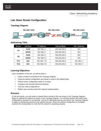
DRIVE SYSTEM
The X axis uses a #25 chain and sprocket drive. These items can be purchased arts.aspx.The chain needs to run the length of the axis on both sides including around the sprockets as shownbelow.Pic 6Use a #25 drive sprocket to connect the motor to the drive sprocket. The Y axis can be driven by chain andsprocket or threaded rod. Use anti backlash nuts for threaded rods to eliminate movement.Join each side of the gantry power drive with a piece of 20mm square steel. Weld a bolt to each end andsuspend from side to side on bearings. See pictureMOTORSWow, big learning curve! I purchased 2 lots of motors before I realised the size and strength of the motorsI needed. In the end I used the 463oz motors to power all three axis. The motors are quite and strongenough to cut most materials (including aluminium) and will give years of trouble free operation. You willalso need 3 drivers a power supply and a breakout board.
Here are the electronics that you will need to make the CNC Router move!You can purchase a bundle of components including three stepper motors, three stepper motor drivers, apower supply, and a breakout board (fan is not included but is recommended if the system is enclosed)here. TING THE MOTORSAttach the lead screw to the motor shaft using flexible connectors. These connectors correct thealignment of the motor to lead screw at the same time as reducing vibration. Connectors can bepurchased from: http://buildyourcnc.com/couplings.aspx.The motors can be mounted on bolts to provide clearance for the connectors as shown.
ELECTRONICSMost of the tutorials on this site are created in response to the difficulties users have with machinesmechanics, structural dimensions and the electronics that drive their CNC machines. Overwhelmingly, theelectronics pose the most difficulty with new users. For an easy to follow wiring demonstration view thevideos available here; px.The installation video explains the wiring instructions that demonstrate a methodology that begins with asimple and straightforward wiring of only one driver and motor and follows with the remaining driverswhile testing throughout. The steps per inch for many forms of mechanical option are also explained indepth.SOFTWAREAfter months of reviewing software options, (there are over 60 options) including the 'miss' purchase ofseveral programs that were not compatible, I have finally worked out the cheapest, easiest and bestsoftware.The software toolchain can contain three software applications.Firstly, a drawing program such as Auto CAD that can manufacture 3D drawings, second, a program thatcan convert the drawing into a toolpath, CAM, and thirdly software to convert the toolpath intomechanical motion. Sound complicated? Well it is up until now!AutoCAD retails for thousands of dollars, CAM programs start at around 1000 and most do notsatisfactorily work. The final program will cost around 300 but you can get a FREE trial to test yoursystem.So all up, with the information in this manual you can download and start manufacturing FREE!!!Software Explained. What to use.Use Google Sketchup to draw your designs in 3D. Google sketchup is free. Download the following softwareand save to your computer.
The CAM program can read your exported DXF files. DXF files contain the 3D information of yourexported drawing. I have tried many CAM programs and they all have their limitations. The mostexpensive is not necessarily the best. In my opinion, the easiest to use is the best! I have settled onMeshCAM as it is compatible with Sketchup (with the addition of the plugin), and is easy to use.Meshcam produces a 'G Code' that can be read by the machine operating software (Mach 3).MeshCAM requires Windows XP/Vista/Windows 7 and at least 512 MB RAM (2GB Preferred).Download a FREE 30 day trial from: http://www.grzsoftware.com/std.php. Choose 'save' to save thefiles to your desktop. Meshcam will install a shortcut on your desktop.
The MACH 3 console above is the control centre of your CNC router. In Mach 3 you can load a GCode and run it. You can configure motors, workbench size and many more options.Download a FREE limited edition of Mach3 R3.043.022from: http://www.machsupport.com/downloads.php.1. Draw in google Sketchup
2. Under 'tools', export as a DXF file3. Open DXF file in Meshcam4. Set toolpath and save as (G Code) .nc file5. Load the G Code into MACH 3.When you hit the program start button the machine will execute the toolpath set. It is highlyrecommended to connect your power to an emergency stop button!Perform a dry run before cutting material.WARNING!!KEEP HANDS CLEAR, DANGEROUS FORCES AT WORK!
CNC BASICS A CNC machine is probably the most useful tool a hobbyist can own, but the price for a CNC machine on the market is way more than the average hobbyist is willing to spend. Build your own CNC explains how to build, program and manufacture your ow


![Welcome [dashdiet.me]](/img/17/30-day-weight-loss-journal.jpg)