Transcription
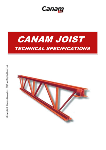
CANAM JOISTTECHNICAL SPECIFICATIONS
Table of ContentsMATERIAL AND ACCESSORIES . .JOIST EXTENSIONS .Axes conventions . 1Details on extensions . 8Properties . 1SPECIAL CONDITIONS . .LOADS .Authorized concentrated loads on joists . 9Geometry and shapes . 3Copyright Canam Group Inc., 2015, All Rights ReservedStandard shape . 3Non-standard shapes . 3STANDARD DETAILS .Shoes . 3Typical standard (Joist on steel beam) . 10Special loads and moments . 4Typical standard (Joist on steel Canam truss) . 15Uniform loads . 4Knee brace details between joist and trusses . 15Partial loads . 4Typical standard (Joist on steel channel) . 16Concentrated loads . 4Knee brace details between joist and steel beam 16Axial loads . 4Moment loads . 4STEEL DECKING.Standard fastening . 17RESTRAINT . .Special fastening for horizontal wind bracing . 17Restraint line requirements . 5HORIZONTAL BRACING .Spacing for restraint . 5Specifications . 18Type of restraint . 6Horizontal lacing for wind post . 18Anchorage of restraint . 6Lacing connection on steel beam . 18Lacing connection on Canam truss . 20DUCT OPENINGS . .Horizontal wind/seismic bracing . 22Maximum duct openings . 7Connections joist to steel beam. 22Dimensions of free openings. 7Connections joists to Canam truss . 23Canam Joist Technical SpecificationsPage I/24
MATERIAL AND ACCESSORIESAXES CONVENTIONSCopyright Canam Group Inc., 2015, All Rights ReservedRound barsU shapesTrussAnglePROPERTIESROUND BARSMaterialGrade(Diameter)fy(mm)MPa12 mm rod23516 mm rodFormingMassAreaInertiaRadius ofgyrationkg/mmm2x103 2013.2174.0018 mm rod235Hot-rolled2.002545.1534.5020 mm rod235Hot-rolled2.473147.8545.0022 mm rod235Hot-rolled2.9838011.4995.5025 mm rod235Hot-rolled3.8549119.1746.25U SHAPESMaterialAxis Y-YGradeMassAreaInertiafyRadius ofAxis Z-ZInertiagyrationRadius ofgyration(mm)MPakg/mmm2x103 mm4(mm)x103 82Canam Joist Technical SpecificationsPage 1/24
DOUBLE ANGLES (LONG LEGS BACK-TO-BACK)Copyright Canam Group Inc., 2015, All Rights ReservedEQUAL DOUBLE ANGLESyAxis Y-YInertia2mmx10 5X3 (45)LL30X30X3 (45)LL35X35X3.5 (45)LL40X40X4 (45)LL40X40X5 (45)LL45X45X4,5 (45)LL45X45X5 (45)LL50X50X3 (45)LL50X50X4 (45)LL50X50X5 (45)LL50X50X6 (45)LL60X60X5 (45)LL60X60X6 (45)LL70X70X6 (45)LL70X70X7 (45)LL80X80X8 (45)LL90X90X9 (45)LL100X100X7 (45)LL100X100X8 (45)LL100X100X10 (45)LL120x120x12 (45)LL150x150x15 (45)LL180x180x18 (45)LL200x200x20 1.6024.4030.0043.2467.5497.20119.8764Radius 6430.5530.7836.5445.6954.9061.10Axis Z-Z withAxis Vgap of 45mmSingle AngleInertiaRadius of Radius ofgyrationgyration64x10 9.3035.2039.20UNEQUAL DOUBLE ANGLESAxis Y-Y withAxis Vgap of 45mmSingle AngleInertiaRadius of Radius ofgyrationgyrationMaterialGradefyMassAreayAxis X-XInertia(mm)MPakg/mmm2mmx106 mm4(mm)x106 mm4(mm)mmLL50X30X5 (45)LL60X40X5 (45)LL60X40X6 (45)LL70X50X6 (45)LL70X50X7 (45)LL80X50X7 (45)LL80X60X7 488.708.6510.7010.6010.7012.80Canam Joist Technical SpecificationsRadius ofgyrationPage 2/24
SPECIAL CONDITIONSGEOMETRY AND SHAPESThe geometry refers to the web profile system. The standardgeometry is presented below.SHOESStandard shoe dimensions vary according to the product and span:Joist shoe in a diaphragm roof with steel deckProductJoistTrussSpan0-15200 mm15200 mm and overAll lengthsDepth100 mm150 mm200 mmMin. length100 mm100 mm150 mmJoist shoe with roofing with horizontal bracingProductJoistCopyright Canam Group Inc., 2015, All Rights ReservedTrussIn some cases, a joist can have two (2) geometrical types. Forarchitectural considerations, the building designer can specify afixed geometry applicable to a joist group. More than onegeometrical type may be specified. However, panel alignment ofjoists with varying lengths and loading conditions may not bepossible.Span0-15200 mm15200 mm and overAll lengthsDepth120 mm120 mm200 mmMin. length100 mm100 mm150 mmThe shoe depth must always be specified at the gridline. Forjoists on which the left and right bearings are not at the same level(sloped joist), the exterior and interior shoe depths are determinedso as to respect the depth at the gridline.The shape of the joist can depend on its use and the type of roofingsystem requested by the customer. It can have one or more of thefollowing shapes:STANDARD SHAPENON-STANDARD SHAPES **To ensure that the intersection point of the end diagonal and the topchord sits above the bearing, the minimum shoe depth should bespecified according to the slope of the joist and the clearance of thesupporting member from the gridline.Minimum shoe depth (mm)** Non-standard shapes and special shapes costmore given their additional complexity.Canam Joist Technical SpecificationsClearance of Joist slope (%)bearing (mm) 1756%150175225275Page 3/24
SPECIAL LOADS AND MOMENTSSpecial loads and moments are classified as follows: permanent,service, seismic and wind loads. Loads applied to joists and joistgirders can be uniform, partial, concentrated, axial or moment. Forlimit state designs, loads are factored and combined to determinethe worst-case scenario.When a moment connection is applied to the ends of a joist(Figure 1), axial loads are created on the top and bottom chords ofthe joist (Figure 2). For the top chord, the load is applied to thebottom of the shoes. This causes an eccentricity at the point. Tocounter this problem, a transfer piece (Figure 3) is used to transferthe load to the first panel point of the top chord.UNIFORM LOADSCopyright Canam Group Inc., 2015, All Rights ReservedPARTIAL LOADSSNOW PILE-UP LOADSCONCENTRATED LOADSAxial loadDouble angles, tube or insidechannelAXIAL LOADSA plate welded to the joist's bottom chord (Figure 4) is used totransfer the axial load from the column to thebottomchord.interiorchannel.TypicalMOMENT LOADSCanam Joist Technical SpecificationsPage 4/24
RESTRAINTRESTRAINT LINE REQUIREMENTSThe following tables are a guide to evaluate the number of top and bottom chord restraint lines for a joisthaving a uniformly distributed load.TABLE FOR SELECTING THE NUMBER OF RESTRAINT LINESCopyright Canam Group Inc., 2015, All Rights ReservedSpanFactored load (KN/m)(m)8910111213141516171819x 42222233333444 x 7222223333344Spanx 7111222223333LEGEND:Factored load (kN/m)(m)202122232425283034384246x 44445555666773 lines4 x 7444555555566x 74444444455554 linesSPACING FOR RESTRAINTMAXIMUM JOIST SPACING (mm) FOR HORIZONTAL RESTRAINTL20x20x31140L25x25x31440Horizontal RestraintL30x30x3 3510Diagonal 549452444964466MAXIMUM JOIST SPACING (mm) FOR DIAGONAL RESTRAINTJoistdepth te: The diagonal restraint must be tied at mid-length.Canam Joist Technical SpecificationsPage 5/24
TYPE OF RESTRAINTEach line of restraint must be adequately anchored at each end tosturdy walls or the main components of the structural frame, ifpracticable. If not practical, diagonal and horizontal restraint will beprovided in combination between adjacent joists near the ends ofthe restraint lines.The ends of joists designed to bear on their bottom chords must beheld adequately in position using attachments to the walls orstructural frame or with lines of restraint at the ends except wheresuch ends are built into the masonry or concrete walls.ANCHORAGE OF RESTRAINTCopyright Canam Group Inc., 2015, All Rights ReservedThe ends of restraint lines can be anchored to the adjacent steelframe or adjacent concrete or masonry walls as shown in Figure 1.If attachment to the adjacent steel frame or walls is not practicable,diagonal and horizontal restraint will be provided in combinationbetween adjacent joists near the ends of the restraint lines as shownin Figure 2. Joists bearing on the bottom chord will require restraintat the ends of the top chord.(a)Diagonal and horizontal restraintFigure 2Bracing of joist restraintDetail 1 below illustrates the restraint connection on a steel element.This steel element can be a UB beam, channel or welded wideflange. The gusset plate is 6 mm thick.1Plate 6mm2(a)Anchorage of restraint to steel beam (bolted)Detail 1Detail 2 illustrates the plate welded on the joist verticals. The sameplate can be installed on a U shape welded to the bottom chord. Themaximum distance between the extreme fibre of the bottom chordand the hole must be never greater than 150 mm in order to avoidany eccentricities.(b)Anchorage of restraint to walls (side connection)(c)Anchorage of restraint to walls (top connection)Figure 1Anchorage of joist restraintCanam Joist Technical SpecificationsDetail 2Page 6/24
Copyright Canam Group Inc., 2015, All Rights ReservedDUCT OPENINGSCanam Joist Technical SpecificationsPage 7/24
JOIST EXTENSIONSDETAILS ON EXTENSIONSCopyright Canam Group Inc., 2015, All Rights ReservedAn extension designates a continuation beyond the normal bearing of the joist. The extension can be the top chord only or the full depth of thejoist, in which case, it is referred to as cantilever joist.TOP CHORD EXTENSIONCANTILEVER JOISTThe extended top chord section varies according to the following conditions: design loads, extension length, deflection criterion and the status ofbearings and anchorage. The section can be reinforced if required. In a section without reinforcement, the extension material is the same as thetop chord of the joist.A reinforcement section has two (2) or four (4) angles as extension material, or one (1) or two (2) channels with a higher capacity than that of thetop chord between the bearings. Also, a reinforced section projects into one or several interior panels so that the joist can resist the bending andshearing forces caused by the extension of the top chord.Canam Joist Technical SpecificationsPage 8/24
LOADSAUTHORIZED CONCENTRATED LOADS ON JOISTSThe concentrated loads must be verified carefully in order to avoid any overstress in the members between panel points (unless these loads werecalculated in the initial design).Without extra verification, only one load should be on one panel point or at 150 mm maximum on both sides of the panel point; moreover, the loadshould be under 200 kg and must remain inside the mechanical load included in the permanent load.Unauthorized loadWithout reinforcement except theload of the roof by itselfCopyright Canam Group Inc., 2015, All Rights ReservedAuthorized loadAuthorized loadHANGING UP LOADS ON JOIST PANEL POINTSAuthorized loadWithout verification (200 kg maximum)150 mm max150 mm maxAuthorized loadWithout verification (200 kg maximum)HOW TO HANG UP A LOAD ON A JOISTUNAUTHORIZED METHODEXCEPT SPRINKLERS(SEE NOTE)AUTHORIZED METHODConcentrated loadsupportConcentrated loadsupportWeldingConcentrated loadsupportNote: For sprinklers, t
Joist shoe in a diaphragm roof with steel deck Product Span Depth Min. length Joist 0-15200 mm 100 mm 100 mm 15200 mm and over 150 mm 100 mm Truss All lengths 200 mm 150 mm Joist shoe with roofing with horizontal bracing Product Span Depth Min. length Joist 0-15200 mm 120 mm 100 mm 15200 mm and over 120 mm 100 mm