Transcription
ESP32 DatasheetEspressif SystemsOctober 8, 2016
About This GuideThis document provides introduction to the specifications of ESP32 hardware.The document structure is as follows:ChapterTitleSubjectAn overview of ESP32, including featured solutions, basicChapter 1Overviewand advanced features, applications and development supportChapter 2Pin DefinitionsIntroduction to the pin layout and descriptionsChapter 3Functional DescriptionDescription of the major functional modulesChapter 4Peripheral InterfaceDescription of the peripheral interfaces integrated on ESP32Chapter 5Electrical CharacteristicsThe electrical characteristics and data of ESP32Chapter 6Package InformationThe package details of ESP32Chapter 7Supported ResourcesThe related documents and community resources for ESP32AppendixTouch SensorThe touch sensor design and layout guidelinesRelease NotesDateVersionRelease notes2016.08V1.0First releaseDisclaimer and Copyright NoticeInformation in this document, including URL references, is subject to change without notice. THIS DOCUMENT ISPROVIDED AS IS WITH NO WARRANTIES WHATSOEVER, INCLUDING ANY WARRANTY OF MERCHANTABILITY, NON-INFRINGEMENT, FITNESS FOR ANY PARTICULAR PURPOSE, OR ANY WARRANTY OTHERWISEARISING OUT OF ANY PROPOSAL, SPECIFICATION OR SAMPLE.All liability, including liability for infringement of any proprietary rights, relating to use of information in this document is disclaimed. No licenses express or implied, by estoppel or otherwise, to any intellectual property rightsare granted herein. The Wi-Fi Alliance Member logo is a trademark of the Wi-Fi Alliance. The Bluetooth logo is aregistered trademark of Bluetooth SIG.All trade names, trademarks and registered trademarks mentioned in this document are property of their respectiveowners, and are hereby acknowledged.Copyright 2016 Espressif Inc. All rights reserved.
Contents1 Overview11.111.21.3Featured Solutions1.1.1 Ultra Low Power Solution11.1.2 Complete Integration Solution1Basic Protocols11.2.1 Wi-Fi11.2.2 Bluetooth2MCU and Advanced Features31.3.1 CPU and Memory31.3.2 Clocks and Timers31.3.3 Advanced Peripheral Interfaces31.3.4 Security41.3.5 Development Support41.4Application41.5Block Diagram52 Pin Definitions62.1Pin Layout62.2Pin Description62.3Power Scheme82.4Strapping Pins93 Functional Description103.1103.23.33.43.5CPU and Memory3.1.1 CPU103.1.2 Internal Memory103.1.3 External Flash and SRAM103.1.4 Memory Map11Timers and Watchdogs133.2.1 64-bit Timers133.2.2 Watchdog Timers13System Clocks133.3.1 CPU Clock133.3.2 RTC Clock143.3.3 Audio PLL Clock14Radio143.4.1 2.4 GHz Receiver143.4.2 2.4 GHz Transmitter153.4.3 Clock Generator15Wi-Fi153.5.1 Wi-Fi Radio and Baseband153.5.2 Wi-Fi MAC163.5.3 Wi-Fi Firmware163.5.4 Packet Traffic Arbitration (PTA)16
3.63.7Bluetooth173.6.1 Bluetooth Radio and Baseband173.6.2 Bluetooth Interface173.6.3 Bluetooth Stack173.6.4 Bluetooth Link Controller18RTC and Low-Power Management194 Peripheral Interface214.1General Purpose Input / Output Interface (GPIO)214.2Analog-to-Digital Converter (ADC)214.3Ultra Low Noise Analog Pre-Amplifier214.4Hall Sensor214.5Digital-to-Analog Converter (DAC)214.6Temperature Sensor224.7Touch Sensor224.8Ultra-Lower-Power Coprocessor224.9Ethernet MAC Interface234.10 SD/SDIO/MMC Host Controller234.11 Universal Asynchronous Receiver Transmitter (UART)234.12 I2C Interface244.13 I2S Interface244.14 Infrared Remote Controller244.15 Pulse Counter244.16 Pulse Width Modulation (PWM)244.17 LED PWM254.18 Serial Peripheral Interface (SPI)254.19 Accelerator255 Electrical Characteristics265.1Absolute Maximum Ratings265.2Recommended Operating Conditions265.3RF Power Consumption Specifications275.4Wi-Fi Radio27Bluetooth Radio285.55.65.5.1 Receiver - Basic Data Rate285.5.2 Transmitter - Basic Data Rate285.5.3 Receiver - Enhanced Data Rate295.5.4 Transmitter - Enhanced Data Rate29Bluetooth LE Radio305.6.1 Receiver305.6.2 Transmitter306 Package Information327 Supported Resources337.1Related Documentation337.2Community Resources33
Appendix A - Touch Sensor34Appendix B - Code Examples36
List of Tables1Pin Description62Strapping Pins93Memory and Peripheral Mapping114Functionalities Depending on the Power Modes195Power Consumption by Power Modes206Capacitive Sensing GPIOs Available on ESP32227Absolute Maximum Ratings268Recommended Operating Conditions269RF Power Consumption Specifications2710Wi-Fi Radio Characteristics2711Receiver Characteristics-Basic Data Rate2812Transmitter Characteristics - Basic Data Rate2813Receiver Characteristics - Enhanced Data Rate2914Transmitter Characteristics - Enhanced Data Rate2915Receiver Characteristics - BLE3016Transmitter Characteristics - BLE30
List of Figures1Function Block Diagram52ESP32 Pin Layout63Address Mapping Structure114QFN48 (6x6 mm) Package325A Typical Touch Sensor Application346Electrode Pattern Requirements347Sensor Track Routing Requirements35
1 OVERVIEW1.OverviewESP32 is a single chip 2.4 GHz Wi-Fi and Bluetooth combo chip designed with TSMC ultra low power 40 nmtechnology. It is designed and optimized for the best power performance, RF performance, robustness, versatility,features and reliability, for a wide variety of applications, and different power profiles.1.11.1.1Featured SolutionsUltra Low Power SolutionESP32 is designed for mobile, wearable electronics, and Internet of Things (IoT) applications. It has many featuresof the state-of-the-art low power chips, including fine resolution clock gating, power modes, and dynamic powerscaling.For instance, in a low-power IoT sensor hub application scenario, ESP32 is woken up periodically and only whena specified condition is detected; low duty cycle is used to minimize the amount of energy that the chip expends.The output power of the power amplifier is also adjustable to achieve an optimal trade off between communicationrange, data rate and power consumption.Note:For more information, refer to Section 3.7 RTC and Low-Power Management.1.1.2Complete Integration SolutionESP32 is the most integrated solution for Wi-Fi Bluetooth applications in the industry with less than 10 externalcomponents. ESP32 integrates the antenna switch, RF balun, power amplifier, low noise receive amplifier, filters,and power management modules. As such, the entire solution occupies minimal Printed Circuit Board (PCB)area.ESP32 uses CMOS for single-chip fully-integrated radio and baseband, and also integrates advanced calibrationcircuitries that allow the solution to dynamically adjust itself to remove external circuit imperfections or adjust tochanges in external conditions.As such, the mass production of ESP32 solutions does not require expensive and specialized Wi-Fi test equipment.1.21.2.1Basic ProtocolsWi-Fi 802.11 b/g/n/e/i 802.11 n (2.4 GHz), up to 150 Mbps 802.11 e: QoS for wireless multimedia technology WMM-PS, UAPSD A-MPDU and A-MSDU aggregation Block ACKEspressif Systems1http://www.espressif.com
1.2 Basic Protocols1 OVERVIEW Fragmentation and defragmentation Automatic Beacon monitoring/scanning 802.11 i security features: pre-authentication and TSN Wi-Fi Protected Access (WPA)/WPA2/WPA2-Enterprise/Wi-Fi Protected Setup (WPS) Infrastructure BSS Station mode/SoftAP mode Wi-Fi Direct (P2P), P2P Discovery, P2P Group Owner mode and P2P Power Management UMA compliant and certified Antenna diversity and selectionNote:For more information, refer to Section 3.5 Wi-Fi.1.2.2Bluetooth Compliant with Bluetooth v4.2 BR/EDR and BLE specification Class-1, class-2 and class-3 transmitter without external power amplifier Enhanced power control 10 dBm transmitting power NZIF receiver with -98 dBm sensitivity Adaptive Frequency Hopping (AFH) Standard HCI based on SDIO/SPI/UART High speed UART HCI, up to 4 Mbps BT 4.2 controller and host stack Service Discover Protocol (SDP) General Access Profile (GAP) Security Manage Protocol (SMP) Bluetooth Low Energy (BLE) ATT/GATT HID All GATT-based profile supported SPP-Like GATT-based profile BLE Beacon A2DP/AVRCP/SPP, HSP/HFP, RFCOMM CVSD and SBC for audio codec Bluetooth Piconet and ScatternetEspressif Systems2http://www.espressif.com
1.3 MCU and Advanced Features1.31.3.11 OVERVIEWMCU and Advanced FeaturesCPU and Memory Xtensa Dual-Core 32-bit LX6 microprocessors, up to 600 DMIPS 448 KByte ROM 520 KByte SRAM 16 KByte SRAM in RTC QSPI Flash/SRAM, up to 4 x 16 MBytes Power supply: 2.2 V to 3.6 V1.3.2Clocks and Timers Internal 8 MHz oscillator with calibration Internal RC oscillator with calibration External 2 MHz to 40 MHz crystal oscillator External 32 kHz crystal oscillator for RTC with calibration Two timer groups, including 2 x 64-bit timers and 1 x main watchdog in each group RTC timer with sub-second accuracy RTC watchdog1.3.3Advanced Peripheral Interfaces 12-bit SAR ADC up to 18 channels 2 8-bit D/A converters 10 touch sensors Temperature sensor 4 SPI 2 I2S 2 I2C 3 UART 1 host (SD/eMMC/SDIO) 1 slave (SDIO/SPI) Ethernet MAC interface with dedicated DMA and IEEE 1588 support CAN 2.0 IR (TX/RX) Motor PWM LED PWM up to 16 channels Hall sensor Ultra low power analog pre-amplifierEspressif Systems3http://www.espressif.com
1.4 Application1.3.41 OVERVIEWSecurity IEEE 802.11 standard security features all supported, including WFA, WPA/WPA2 and WAPI Secure boot Flash encryption 1024-bit OTP, up to 768-bit for customers Cryptographic hardware acceleration:– AES– HASH (SHA-2) library– RSA– ECC– Random Number Generator (RNG)1.3.5Development Support SDK Firmware for fast on-line programming Open source toolchains based on GCCNote:For more information, refer to Chapter 7 Supported Resources.1.4Application Generic low power IoT sensor hub Generic low power IoT loggers Video streaming from camera Over The Top (OTT) devices Music players– Internet music players– Audio streaming devices Wi-Fi enabled toys– Loggers– Proximity sensing toys Wi-Fi enabled speech recognition devices Audio headsets Smart power plugs Home automation Mesh networkEspressif Systems4http://www.espressif.com
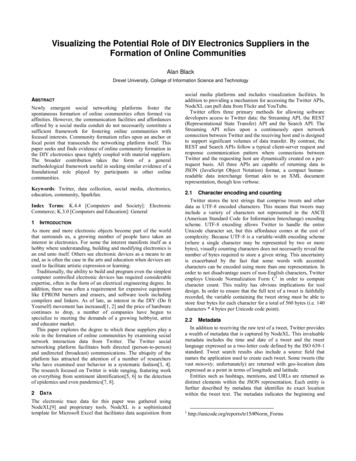
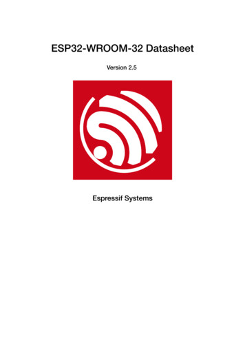
1.5 Block Diagram1 OVERVIEW Industrial wireless control Baby monitors Wearable electronics Wi-Fi location-aware devices Security ID tags Healthcare– Proximity and movement monitoring trigger devices– Temperature sensing loggersBlock ClockgeneratorI2SSDIORF receiveWi-Fi MACWi-FibasebandRFtransmitUARTCANCore and memoryETH2 x Xtensa 32-bit LX6MicroprocessorsCryptographic alunSPISwitch1.5SHARSAAESRNGRTCTouch sensorDACULPcoprocessorPMURecoverymemoryADCFigure 1: Function Block DiagramEspressif Systems5http://www.espressif.com
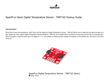
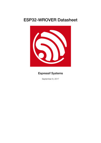
VDDAXTAL PXTAL NVDDAGPIO21U0TXDU0RXDGPIO22GPIO19VDD3P3 CPU46454443424140393837Pin LayoutCAP22.147Pin DefinitionsCAP12.482VDDA136GPIO23LNA IN235GPIO18VDD3P3334GPIO5VDD3P3433SD DATA 1SENSOR VP532SD DATA 0SENSOR CAPP631SD CLKSENSOR CAPN730SD CMDSENSOR VN829SD DATA 3CHIP PU928SD DATA 2ESP32192021222324VDD3P3 IO27121532K XPGPIO26VDD SDIO14GPIO1726GPIO252711131032K XNVDET 1VDET 2PIN DEFINITIONSFigure 2: ESP32 Pin Layout2.2Pin DescriptionTable 1: Pin DescriptionNameNo.TypeFunctionAnalogVDDA1PAnalog power supply (2.3V 3.6V)LNA IN2I/ORF input and outputVDD3P33PAmplifier power supply (2.3V 3.6V)VDD3P34PAmplifier power supply (2.3V 3.6V)VDD3P3 RTCGPIO36, ADC PRE AMP, ADC1 CH0, RTC GPIO0SENSOR VP5INote: Connects 270 pF capacitor from SENSOR VP to SENSOR CAPP when used as ADC PRE AMP.Espressif Systems6http://www.espressif.com
2.2 Pin DescriptionName2No.TypePIN DEFINITIONSFunctionGPIO37, ADC PRE AMP, ADC1 CH1, RTC GPIO1SENSOR CAPP6INote: Connects 270 pF capacitor from SENSOR VP to SENSOR CAPP when used as ADC PRE AMP.GPIO38, ADC1 CH2, ADC PRE AMP, RTC GPIO2SENSOR CAPN7INote: Connects 270 pF capacitor from SENSOR VN to SENSOR CAPN when used as ADC PRE AMP.GPIO39, ADC1 CH3, ADC PRE AMP, RTC GPIO3SENSOR VN8INote: Connects 270 pF capacitor from SENSOR VN to SENSOR CAPN when used as ADC PRE AMP.Chip Enable (Active High)CHIP PU9IHigh: On, chip works properlyLow: Off, chip works at the minimum powerNote: Do not leave CHIP PU pin floatingVDET 110IGPIO34, ADC1 CH6, RTC GPIO4VDET 211IGPIO35, ADC1 CH7, RTC GPIO532K XP12I/O32K XN13I/OGPIO2514I/OGPIO25, DAC 1, ADC2 CH8, RTC GPIO6, EMAC RXD0GPIO2615I/OGPIO26, DAC 2, ADC2 CH9, RTC GPIO7, EMAC RXD1GPIO2716I/OGPIO27, ADC2 CH7, TOUCH7, RTC GPIO17, EMAC RX DVMTMS17I/OMTDI18I/OVDD3P3 4I/OGPIO32,32K XP (32.768 kHz crystal oscillator input),ADC1 CH4, TOUCH9, RTC GPIO9GPIO33, 32K XN (32.768 kHz crystal oscillator output),ADC1 CH5, TOUCH8, RTC GPIO8GPIO14, ADC2 CH6, TOUCH6, RTC GPIO16, MTMS, HSPICLK, HS2 CLK, SD CLK, EMAC TXD2GPIO12, ADC2 CH5, TOUCH5, RTC GPIO15, MTDI, HSPIQ,HS2 DATA2, SD DATA2, EMAC TXD3RTC IO power supply input (1.8V - 3.3V)GPIO13, ADC2 CH4, TOUCH4, RTC GPIO14, MTCK, HSPID,HS2 DATA3, SD DATA3, EMAC RX ERGPIO15,ADC2 CH3,TOUCH3,RTC GPIO13,MTDO,HSPICS0, HS2 CMD, SD CMD, EMAC RXD3GPIO2,ADC2 CH2,TOUCH2,RTC GPIO12,HSPIWP,HS2 DATA0, SD DATA0GPIO0, ADC2 CH1, TOUCH1, RTC GPIO11, CLK OUT1,EMAC TX CLKGPIO4,ADC2 CH0,TOUCH0,RTC GPIO10,HSPIHD,HS2 DATA1, SD DATA1, EMAC TX ERVDD SDIOGPIO1625I/OGPIO16, HS1 DATA4, U2RXD, EMAC CLK OUTVDD SDIO26P1.8V or 3.3V power supply outputGPIO1727I/OGPIO17, HS1 DATA5, U2TXD, EMAC CLK OUT 180SD DATA 228I/OGPIO9, SD DATA2, SPIHD, HS1 DATA2, U1RXDSD DATA 329I/OGPIO10, SD DATA3, SPIWP, HS1 DATA3, U1TXDSD CMD30I/OGPIO11, SD CMD, SPICS0, HS1 CMD, U1RTSSD CLK31I/OGPIO6, SD CLK, SPICLK, HS1 CLK, U1CTSEspressif Systems7http://www.espressif.com
2.3 Power Scheme2NameNo.TypeFunctionSD DATA 032I/OGPIO7, SD DATA0, SPIQ, HS1 DATA0, U2RTSSD DATA 133I/OGPIO8, SD DATA1, SPID, HS1 DATA1, U2CTSPIN DEFINITIONSVDD3P3 CPUGPIO534I/OGPIO5, VSPICS0, HS1 DATA6, EMAC RX CLKGPIO1835I/OGPIO18, VSPICLK, HS1 DATA7GPIO2336I/OGPIO23, VSPID, HS1 STROBEVDD3P3 CPU37PCPU IO power supply input (1.8V - 3.3V)GPIO1938I/OGPIO19, VSPIQ, U0CTS, EMAC TXD0GPIO2239I/OGPIO22, VSPIWP, U0RTS, EMAC TXD1U0RXD40I/OGPIO3, U0RXD, CLK OUT2U0TXD41I/OGPIO1, U0TXD, CLK OUT3, EMAC RXD2GPIO2142I/OGPIO21, VSPIHD, EMAC TX ENAnalogVDDA43I/OAnalog power supply (2.3V - 3.6V)XTAL N44OExternal crystal outputXTAL P45IExternal crystal inputVDDA46PDigital power supply for PLL (2.3V - 3.6V)CAP247ICAP148I2.3Connects with a 3 nF capacitor and 20 kΩ resistor in parallel toCAP1Connects with a 10 nF series capacitor to groundPower SchemeESP32 digital pins are divided into three different power domains: VDD3P3 RTC VDD3P3 CPU VDD SDIOVDD3P3 RTC is also the input power supply for RTC and CPU. VDD3P3 CPU is also the input power supply forCPU.VDD SDIO connects to the output of an internal LDO, whose input is VDD3P3 RTC. When VDD SDIO is connected to the same PCB net together with VDD3P3 RTC; the internal LDO is disabled automatically.The internal LDO can be configured as 1.8V, or the same voltage as VDD3P3 RTC. It can be powered off viasoftware to minimize the current of Flash/SRAM during the Deep-sleep mode.Note:It is required that the power supply of VDD3P3 RTC, VDD3P3 CPU and analog must be stable before the pin CHIP PUis set at high level.Espressif Systems8http://www.espressif.com
2.4 Strapping Pins2.42PIN DEFINITIONSStrapping PinsESP32 has 6 strapping pins: MTDI/GPIO12: internal pull-down GPIO0: internal pull-up GPIO2: internal pull-down GPIO4: internal pull-down MTDO/GPIO15: internal pull-up GPIO5: internal pull-upSoftware can read the value of these 6 bits from the register ”GPIO STRAPPING”.During the chip power-on reset, the latches of the strapping pins sample the voltage level as strapping bits of ”0”or ”1”, and hold these bits until the chip is powered down or shut down. The strapping bits configure the deviceboot mode, the operating voltage of VDD SDIO and other system initial settings.Each strapping pin is connected with its internal pull-up/pull-down during the chip reset. Consequently, if a strapping pin is unconnected or the connected external circuit is high-impendence, the internal weak pull-up/pull-downwill determine the default input level of the strapping pins.To change the strapping bit values, users can apply the external pull-down/pull-up resistances, or apply the hostMCU’s GPIOs to control the voltage level of these pins when powering on ESP32.After reset, the strapping pins work as the normal functions pins.Refer to Table 2 for detailed boot modes configuration by strapping pins.Table 2: Strapping PinsVoltage of Internal LDO (VDD SDIO)PinDefaultMTDIPull-down3.3V1.8V01Booting ModePinDefaultGPIO0Pull-upGPIO2Pull-downSPI BootDownload Boot10Don’t-care0Debugging Log on U0TXD During BootingPinDefaultU0TXD TogglingU0TXD SilentMTDOPull-up10Timing of SDIO ge OutputRising-edge OutputFalling-edge OutputRising-edge OutputPull-up0011Pull-up0101Note:Firmware can configure register bits to change the setting of ”Voltage of Internal LDO (VDD SDIO)” and ”Timing of SDIOSlave” after booting.Espressif Systems9http://www.espressif.com
3 FUNCTIONAL DESCRIPTION3.Functional DescriptionThis chapter describes the functions implemented in ESP32.3.1CPU and Memory3.1.1CPUESP32 contains two low-power Xtensa 32-bit LX6 microprocessors with the following features. 7-stage pipeline to support the clock frequency of up to 240 MHz 16/24-bit Instruction Set provides high code-density Support Floating Point Unit Support DSP instructions, such as 32-bit Multiplier, 32-bit Divider, and 40-bit MAC Support 32 interrupt vectors from about 70 interrupt sourcesThe dual CPUs interface through: Xtensa RAM/ROM Interface for instruction and data Xtensa Local Memory Interface for fast peripheral register access Interrupt with external and internal sources JTAG interface for debugging3.1.2Internal MemoryESP32’s internal memory includes: 448 KBytes ROM for booting and core functions 520 KBytes on-chip SRAM for data and instruction 8 KBytes SRAM in RTC, which is called RTC SLOW Memory and can be used for co-processor accessingduring the Deep-sleep mode 8 KBytes SRAM in RTC, which is called RTC FAST Memory and can be used for data storage and main CPUduring RTC Boot from the Deep-sleep mode 1 Kbit of EFUSE, of which 256 bits are used for the system (MAC address and chip configuration) and theremaining 768 bits are reserved for customer applications, including Flash-Encryption and Chip-ID3.1.3External Flash and SRAMESP32 supports 4 x 16 MBytes of external QSPI Flash and SRAM with hardware encryption based on AES toprotect developer’s programs and data.ESP32 accesses external QSPI Flash and SRAM by the high-speed caches Up to 16 MBytes of external Flash are memory mapped into the CPU code space, supporting 8-bit, 16-bitand 32-bit access. Code execution is supported.Espressif Systems10http://www.espressif.com
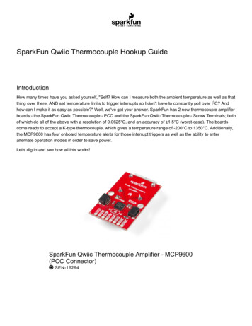
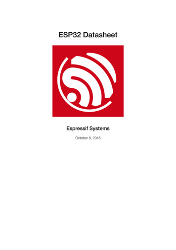
3.1 CPU and Memory3 FUNCTIONAL DESCRIPTION Up to 8 MBytes of external Flash/SRAM are memory mapped into the CPU data space, supporting 8-bit,16-bit and 32-bit access. Data read is supported on the Flash and SRAM. Data write is supported on theSRAM.3.1.4Memory MapThe structure of address mapping is shown in Figure 3. The memory and peripherals mapping of ESP32 is shownin Table 3.Figure 3: Address Mapping StructureTable 3: Memory and Peripheral MappingCategoryEmbeddedTargetStart AddressEnd AddressSizeInternal ROM 00x4000 00000x4005 FFFF384 KBInternal ROM 10x3FF9 00000x3FF9 FFFF64 KBInternal SRAM 00x4007 00000x4009 FFFF192 KB0x3FFE 00000x3FFF FFFF0x400A 00000x400B FFFF0x3FFA E0000x3FFD FFFF0x3FF8 00000x3FF8 1FFF0x400C 00000x400C 1FFF0x5000 00000x5000 1FFF8 KB0x3F40 00000x3F7F FFFF4 MB0x400C 20000x40BF FFFF0x3F80 00000x3FBF FFFFInternal SRAM 1MemoryInternal SRAM 2RTC FAST MemoryRTC SLOW MemoryExternalExternal FlashMemoryExternal SRAMEspressif Systems11128 KB200 KB8 KB11 MB248 KB4 MBhttp://www.espressif.com
3.1 CPU and MemoryCategoryPeripheralEspressif Systems3 FUNCTIONAL DESCRIPTIONTargetStart AddressEnd AddressSizeDPort Register0x3FF0 00000x3FF0 0FFF4 KBAES Accelerator0x3FF0 10000x3FF0 1FFF4 KBRSA Accelerator0x3FF0 20000x3FF0 2FFF4 KBSHA Accelerator0x3FF0 30000x3FF0 3FFF4 KBSecure Boot0x3FF0 40000x3FF0 4FFF4 KBCache MMU Table0x3FF1 00000x3FF1 3FFF16 KBPID Controller0x3FF1 F0000x3FF1 FFFF4 KBUART00x3FF4 00000x3FF4 0FFF4 KBSPI10x3FF4 20000x3FF4 2FFF4 KBSPI00x3FF4 30000x3FF4 3FFF4 KBGPIO0x3FF4 40000x3FF4 4FFF4 KBRTC0x3FF4 80000x3FF4 8FFF4 KBIO MUX0x3FF4 90000x3FF4 9FFF4 KBSDIO Slave0x3FF4 B0000x3FF4 BFFF4 KBUDMA10x3FF4 C0000x3FF4 CFFF4 KBI2S00x3FF4 F0000x3FF4 FFFF4 KBUART10x3FF5 00000x3FF5 0FFF4 KBI2C00x3FF5 30000x3FF5 3FFF4 KBUDMA00x3FF5 40000x3FF5 4FFF4 KBSDIO Slave0x3FF5 50000x3FF5 5FFF4 KBRMT0x3FF5 60000x3FF5 6FFF4 KBPCNT0x3FF5 70000x3FF5 7FFF4 KBSDIO Slave0x3FF5 80000x3FF5 8FFF4 KBLED PWM0x3FF5 90000x3FF5 9FFF4 KBEfuse Controller0x3FF5 A0000x3FF5 AFFF4 KBFlash Encryption0x3FF5 B0000x3FF5 BFFF4 KBPWM00x3FF5 E0000x3FF5 EFFF4 KBTIMG00x3FF5 F0000x3FF5 FFFF4 KBTIMG10x3FF6 00000x3FF6 0FFF4 KBSPI20x3FF6 40000x3FF6 4FFF4 KBSPI30x3FF6 50000x3FF6 5FFF4 KBSYSCON0x3FF6 60000x3FF6 6FFF4 KBI2C10x3FF6 70000x3FF6 7FFF4 KBSDMMC0x3FF6 80000x3FF6 8FFF4 KBEMAC0x3FF6 90000x3FF6 AFFF8 KBPWM10x3FF6 C0000x3FF6 CFFF4 KBI2S10x3FF6 D0000x3FF6 DFFF4 KBUART20x3FF6 E0000x3FF6 EFFF4 KBPWM20x3FF6 F0000x3FF6 FFFF4 KBPWM30x3FF7 00000x3FF7 0FFF4 KBRNG0x3FF7 50000x3FF7 5FFF4 KB12http://www.espressif.com
3.2 Timers and Watchdogs3.23 FUNCTIONAL DESCRIPTIONTimers and Watchdogs3.2.164-bit TimersThere are four general-purpose timers embedded in the ESP32. They are all 64-bit generic timers which are basedon 16-bit prescalers and 64-bit auto-reload-capable up/downcounters.The timers feature: A 16-bit clock prescaler, from 2 to 65536 A 64-bit time-base counter Configurable up/down time-base counter: incrementing or decrmenting Halt and resume of time-base counter Auto-reload at alarming Software-controlled instant reload Level and edge interrupt generation3.2.2Watchdog TimersThe ESP32 has three watchdog timers: one in each of the two timer modules (called the Main Watchdog Timer,or MWDT) and one in the RTC module (called the RTC Watchdog Timer, or RWDT). These watchdog timers areintended to recover from an unforeseen fault, causing the application program to abandon its normal sequence. Awatchdog timer has 4 stages. Each stage may take one of three or four actions on expiry of a programmed timeperiod for this stage unless the watchdog is fed or disabled. The actions are: interrupt, CPU reset, and core reset,and system reset. Only the RWDT can trigger the system reset, and is able to reset the entire chip, including theRTC itself. A timeout value can be set for each stage individually.During Flash boot the RWDT and the first MWDT start automatically in order to detect and recover from bootingproblems.The ESP32 watchdogs have the following features: 4 stages, each can be configured or disabled separately Programmable time period for each stage One of 3 or 4 possible actions (interrupt, CPU reset, core reset, and system reset) on expiration of each stage 32-bit expiry counter Write protection, to prevent the RWDT and MWDT configuration from being inadvertently altered SPI Flash boot protectionIf the boot process from an SPI Flash does not complete within a predetermined time period, the watchdogwill reboot the entire system.3.33.3.1System ClocksCPU ClockUpon reset, an external crystal clock source (2 MHz 60 MHz), is selected as the default CPU clock. The externalcrystal clock source also connects to a PLL to generate a high frequency clock (typically 160 MHz).Espressif Systems13http://www.espressif.com
3.4 Radio3 FUNCTIONAL DESCRIPTIONIn addition to this, ESP32 has an internal 8 MHz oscillator, of which the accuracy is guaranteed by design andis stable over temperature (within 1% accuracy). Hence, the application can then select from the external crystalclock source, the PLL clock or the internal 8 MHz oscillator. The selected clock source drives the CPU clock,directly or after division, depending on the application.3.3.2RTC ClockThe RTC clock has five possible sources: external low speed (32 kHz) crystal clock external crystal clock divided by 4 internal RC oscillator (typically about 150 kHz and adjustable) internal 8 MHz oscillator internal 31.25 kHz clock (derived from the internal 8 MHz oscillator divided by 256)When the chip is in the normal power mode and needs faster CPU accessing, the application can choose theexternal high speed crystal clock divided by 4 or the internal 8 MHz oscillator. When the chip operates in the lowpower mode, the application chooses the external low speed (32 kHz) crystal clock, the internal RC clock or theinternal 31.25 kHz clock.3.3.3Audio PLL ClockThe audio clock is generated by the ultra low noise fractional-N PLL. The output frequency of the audio PLL isprogrammable, from 16 MHz to 128 MHz, given by the following formula:fout fxtal NdivKMdiv 2 divwhere fout is the output frequency, fxtal is the frequency of the crystal oscillator, and Ndiv , Mdiv and Kdiv are allinteger values, configurable by registers.3.4RadioThe ESP32 radio consists of the following main blocks: 2.4 GHz receiver 2.4 GHz transmitter bias and regulators balun and transmit-receive switch clock generator3.4.12.4 GHz ReceiverThe 2.4 GHz receiver down-converts the 2.4 GHz RF signal to quadrature baseband signals and converts themto the digital domain with 2 high-resolution, high-speed ADCs. To adapt to varying signal channel conditions,RF filters, Automatic Gain Control (AGC), DC offset cancelation circuits and baseband filters are integrated withinESP32.Espressif Systems14http://www.espressif.com
3.5 Wi-Fi3.4.23 FUNCTIONAL DESCRIPTION2.4 GHz TransmitterThe 2.4 GHz transmitter up-converts the quadrature baseband signals to the 2.4 GHz RF signal, and drives theantenna with a high powered Complementary Metal Oxide Semiconductor (CMOS) power amplifier. The use ofdigital calibration further improves the linearity of the power amplifier, enabling state-of-the-art performance ofdelivering 20.5 dBm of average power for 802.11b transmission and 17 dBm for 802.11n transmission.Additional calibrations are integrated to cancel any imperfections of the radio, such as: Carrier leakage I/Q phase matching Baseband nonlinearities RF nonlinearities Antenna matchingThese built-in calibration routines reduce the amount of time and required for product test and make test equipmentunnecessary.3.4.3Clock GeneratorThe clock generator generates quadrature 2.4 GHz clock signals for the receiver and transmitter. All componentsof the clock generator are integrated on the chip, including all inductors, varactors, filters, regulators and dividers.The clock generator has built-in calibration and self test circuits. Quadrature clock phases and phase noise areoptimized on-chip with patented calibration algorithms to ensure the best performance of the receiver and transmitter.3.5Wi-FiESP32 implements TCP/IP, full 802.11 b/g/n/e/i WLAN MAC protocol, and Wi-Fi Direct specification. It supportsBasic Service Set (BSS) STA and SoftAP operations under the Distributed Control Function (DCF) and P2P groupoperation compliant with the latest Wi-Fi P2P protocol.Passive or active scanning, as well as the P2P discovery procedure are performed autonomously when initiatedby appropriate commands. Power management is handled with minimum host interaction to minimize active dutyperiod.3.5.1Wi-Fi Radio and BasebandThe ESP32 Wi-Fi Radio and Baseband support the following features: 802.11b and 802.11g data-rates 802.11n MCS0-7 in both 20 MHz and 40 MHz bandwidth 802.11n MCS32 802.11n 0.4 µS guard-interval Data-rate up to 150 Mbps Receiving STBC 2x1 Up to 21 dBm transmitting power Adjustable transmitting powerEspressif Systems15http://www.espressif.com
3.5 Wi-Fi3 FUNCTIONAL DESCRIPTION Antenna diversity and selection (software-managed hardware)3.5.2Wi-Fi MACThe ESP32 Wi-Fi MAC applies low level protocol functions automatically as follows: Request To Send (RTS), Clear To Send (CTS) and Acknowledgement (ACK/BA) Fragmentation and defragmentation Aggregation AMPDU and AMSDU WMM, U-APSD 802.11 e: QoS for wireless multimedia technology CCMP (CBC-MAC, counter mode), TKIP (MIC, RC4), WAPI (SMS4), WEP (RC4) and CRC Frame encapsulation (802.11h/RFC 1042) Automatic beacon monitoring/scanning3.5.3Wi-Fi FirmwareThe ESP32 Wi-Fi Firmware provides the following functions: Infrastructure BSS Station mode / P2P mode / softAP mode support P2P Discovery, P2P Group Owner, P2P Group Client and P2P Power Management WPA/WPA2-Enterprise and WPS driver Additional 802.11i security features such as pre-authentication and TSN Open interface for various upper layer authentication schemes over EAP such as TLS, PEAP, LEAP, SIM,AKA or customer specific Clock/power gating combined with 802.11-compliant power management dynamically adapted to currentconnection condition providing minimal power consumption Adaptive rate fallback algorithm sets the optimal transmission rate and transmit power based on actual SignalNoise Ratio (SNR) and packet loss information Automatic retransmission and response on MAC to avoid packet discarding on slow host environment3.5.4Packet Traffic Arbitration (PTA)ESP32 has a configurable Packet Traffic Arbitration (PTA) that provides flexible and exact timing Bluetooth coexistence support. It is a combination of both Frequency Division Multiplexing (FDM) and Time Division Multiplexing(TDM), and coordinates the protocol stacks. It is preferable that Wi-Fi works in the 20 MHz bandwidth mode to decrease its interference with BT. BT applies AFH (Adaptive Frequency Hopping) to avoid using the channels within Wi-Fi bandwidth. Wi-Fi MAC limits the time duration of Wi-Fi packets, and does not transmit the long Wi
1 OVERVIEW 1. Overview ESP32 is a single chip 2.4 GHz Wi-Fi and Bluetooth combo chip designed with TSMC ultra low power 40 nm technology. It is designed and optimized for the best power performance, RF performance, robustness, versatility,