Transcription
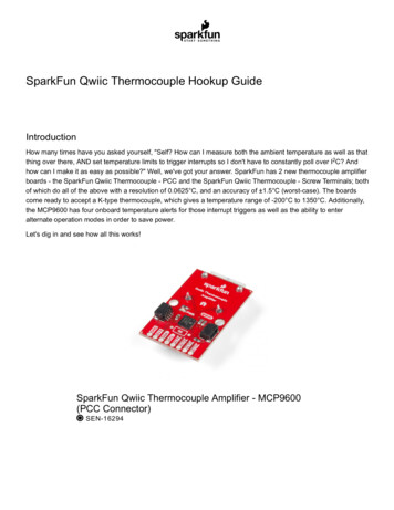
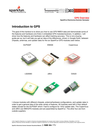
GPS OverviewSparkFun Electronics Summer SemesterIntroduction to GPSThe goal of this handout is to show you how to use GPS NMEA data and demonstrate some ofthe features and hardware one finds in embedded GPS modules/receivers. In addition, I willshow how the features and hardware can affect tracking accuracy. This is not a buyingguide per se, but it will help you get an idea of the differences, shown in Google Earth, betweenchipsets, antennas, and update rates for the six SparkFun GPS modules seen below.SUP500FLS23060EM406CopernicusuMiniD2523I choose modules with different chipsets, antenna/hardware configurations, and update rates inorder to get a general idea of the wide variety of features. All modules were left in their defaultstates (except for the SUP500F which I had to configure for 10Hz update rate). The Copernicusand uMini use SMDGPS modules and are assembled by SparkFun. The other four are fromoutside suppliers. 2011 SparkFun Electronics, Inc. SparkFun Electronics Educational Materials are Licensed under Creative Commons Attribution -ShareAlike, CC BY-SASparkFun Electronics Summer Semester is a trademark of SparkFun Electronics, Inc. All other trademarks contained herein are the property of their respective owners.SparkFun Electronics Summer Semester Educational Material
GPS OverviewSparkFun Electronics Summer SemesterGPS ModuleChipsetAntennaUpdate RateCopernicusTrimble Trim Coreceramic patch1HzSUP500FVenus634small ceramic patch10HzMN5010 (uMini) SiRF Star IIIchip1HzLS23060MediaTek MT3318ceramic patch5HzDS2523TU-Blox 5helical4HzEM-406ASiRF Star IIIceramic patch1HzRefer to individual product pages and datasheets for the detailed technical information for eachmodule. 2011 SparkFun Electronics, Inc. SparkFun Electronics Educational Materials are Licensed under Creative Commons Attribution -ShareAlike, CC BY-SASparkFun Electronics Summer Semester is a trademark of SparkFun Electronics, Inc. All other trademarks contained herein are the property of their respective owners.SparkFun Electronics Summer Semester Educational Material
GPS OverviewSparkFun Electronics Summer SemesterBuilding the testerHere is the bill of materials (BOM) for testing each GPS module: Breadboard Power Supply Stick 3.3/5VLiPo Battery Pack 1000mAh/7.2VopenloguSD 1GBjumper wires and headersThe following are some issues that I had to consider when designing the test rig.GPS modules are radio frequency receivers.For reliable performance, your GPS module needs to receive good unobstructed signals fromthe satellite constellation. GPS modules have relatively tiny antennas to receive data fromsatellites moving at relativistic orbital speeds, over 10,000 miles away, and so they needsomewhat of a clear view of the sky. I know this might sound really obvious, but I cannot stressthis enough, because.GPS sensitivity and accuracy is highly dependent on environmental conditions.Not only does this include physical objects, like trees, earth, and structures, but also includesatmospheric effects, space weather, the overall health of the GPS constellation, and multipathinteractions, all of which contribute to constant variability in receiving the GPS signal. Tominimize errors due to these environmental effects, I wanted to test and track all six modules atthe same time with varying views of the sky.What I needed was a mobile logger for each GPS module. SparkFun stocks more than enoughsupplies to accomplish this.SparkFun Electronics now carries a GPS shield unit that will make hooking up your GPSmodule to your Arduino as easy as soldering some headers and placing the shield onto yourArduino. 2011 SparkFun Electronics, Inc. SparkFun Electronics Educational Materials are Licensed under Creative Commons Attribution -ShareAlike, CC BY-SASparkFun Electronics Summer Semester is a trademark of SparkFun Electronics, Inc. All other trademarks contained herein are the property of their respective owners.SparkFun Electronics Summer Semester Educational Material
GPS OverviewSparkFun Electronics Summer SemesterTracking Setup. Note: The uMini was oriented vertically for the test and is not shown that way inthe pictureConnection Block DiagramEach GPS module should have its own clean (regulated and decoupled) DC powersupply.The GPS power supply feeds into the antenna power supply on some of the modules, so anyexcessive noise or unexpected loading on the circuit can affect performance. Attaching a highcapacity LiPo battery to a regulated Breadboard Power Supply Stick for the power supply foreach module is sufficient. 2011 SparkFun Electronics, Inc. SparkFun Electronics Educational Materials are Licensed under Creative Commons Attribution -ShareAlike, CC BY-SASparkFun Electronics Summer Semester is a trademark of SparkFun Electronics, Inc. All other trademarks contained herein are the property of their respective owners.SparkFun Electronics Summer Semester Educational Material
GPS OverviewSparkFun Electronics Summer SemesterNext, I capture the data coming out of the GPS module with the openlog.All that needs to be done is to connect the transmit pin (TX) from the GPS module to the receive(RX) pin on the openlog. The openlog will log anything it sees on that pin, just be sure toconfigure the baud rate on the openlog to match the baud rate coming out of the GPS module.A brief word or two on the VBATT pin and the TTFF (time to first fix).What is the VBATT pin used for? Some embedded GPS modules contain volatile RAM that isused to store the almanac and ephemeris data of the satellites, which is globally updated on aregular basis. Think of the almanac data as a "bus schedule" of when and where each satellitewill be in the sky. The ephemeris data contains the errors in the schedule. If your GPS receiverdoes not have the schedule or the errors of the satellites, it will have to download thatinformation when there are updates. Since the RAM stores this data, the VBATT pin should bepowered or connected to some kind of energy supply (i.e. supply voltage, battery, orsupercapcitor), so that your GPS module can quickly start-up. If you don't power the RAM, all ofthe almanac and ephemeris data is lost with each power cycle.The TTFF (time to first fix) is determined by how quickly the GPS module can access thealmanac and ephemeris data. If the module doesn't have any of this data (some modules don'thave this data out-of-the-box) the module might take a bit of time to power up. Same goes for ifyou don't connect power to the VBATT (RAM power) pin, you will lose all of the data upon apower cycle. If the almanac and ephemeris data can be permanently stored in flash, like theSUP500F can, then you should get a really fast TTFF. Some modules, like the EM406, have asupercapacitor attached to the RAM. This means you will get really quick TTFF for only a periodof time after you power the module down. Wait too long, the capacitor will discharge and you willlose your information. The reason for the choice in using a supercap over a battery or flash chip,is that it is in expensive, small, and the almanac and ephemeris data needs to be updatedregularly anyway, so if your position is changing a great deal over the globe, you don't need tokeep all of the same almanac data.In terms of the TTFF performance for each of these modules, all have similar stated fix timesthat are under 1 minute, but will differ with environmental conditions and antenna hardware. 2011 SparkFun Electronics, Inc. SparkFun Electronics Educational Materials are Licensed under Creative Commons Attribution -ShareAlike, CC BY-SASparkFun Electronics Summer Semester is a trademark of SparkFun Electronics, Inc. All other trademarks contained herein are the property of their respective owners.SparkFun Electronics Summer Semester Educational Material
GPS OverviewSparkFun Electronics Summer SemesterTrackingDownload Google Earth to view the KMZ files and zoom around my track in 3D (be sure to turnon 3D buildings). Just click the link and Google Earth should open and zoom to the SparkFunbuilding. raw KMZedited for locks KMZOverviewFor my track, I decided to walk the GPS modules around the SparkFun building, instead oftesting them in a car. GPS modules, to an extent, seem to work better the faster theymove, so walking the units around the building should create a test condition where the GPSmodules will have a greater chance to show errors. 2011 SparkFun Electronics, Inc. SparkFun Electronics Educational Materials are Licensed under Creative Commons Attribution -ShareAlike, CC BY-SASparkFun Electronics Summer Semester is a trademark of SparkFun Electronics, Inc. All other trademarks contained herein are the property of their respective owners.SparkFun Electronics Summer Semester Educational Material
GPS OverviewSparkFun Electronics Summer SemesterActual track walked (top is Northish).Here is a brief summary of my track: I turned all of the module's power ON next to a windowon the second floor of the SparkFun building. I waited a few minutes, then made my way outsideto the north most point of the parking lot, where I waited to make sure all of the modules had alock before I proceeded south around the building and back to where I started. 2011 SparkFun Electronics, Inc. SparkFun Electronics Educational Materials are Licensed under Creative Commons Attribution -ShareAlike, CC BY-SASparkFun Electronics Summer Semester is a trademark of SparkFun Electronics, Inc. All other trademarks contained herein are the property of their respective owners.SparkFun Electronics Summer Semester Educational Material
GPS OverviewSparkFun Electronics Summer SemesterWhat does it mean when the receiver has a lock or a fix?When the receiver has a lock, you get accurate position (3D) and time data. This isaccomplished when the receiver sees at least four satellites in good view. Why four? You wouldthink you only need three for triangulation, right? You forgot about time! Remember, with fourunknown variables you need four equations. The fourth signal gives enough information for yourGPS unit to compute all three positions (latitude, longitude, elevation) and time.Getting accurate time is not an easy task for satellites and receivers alike. The GPS satellitesneed really, I mean really, accurate timing. So accurate, that there are actually atomic clocks onboard the satellites in order to keep them in sync. Since the speeds and distances are so greatbetween satellites and receivers, relativistic offsets are programmed into the satellites positionand time data. This information, along with additional correction data the satellites receive frompermanent ground based stations (this is how WAAS works), turns your GPS receiver into anamazingly accurate and powerful little device with, on average, five meter accuracy.RED Copernicus, BLUE uMini, GREEN EM406, ORANGE D2523, LIGHT BLUE SUP500, GREEN-BLUE LS23060, YELLOW actual path*North is at the top* 2011 SparkFun Electronics, Inc. SparkFun Electronics Educational Materials are Licensed under Creative Commons Attribution -ShareAlike, CC BY-SASparkFun Electronics Summer Semester is a trademark of SparkFun Electronics, Inc. All other trademarks contained herein are the property of their respective owners.SparkFun Electronics Summer Semester Educational Material
GPS OverviewSparkFun Electronics Summer SemesterThis view only shows latitude and longitude data (no elevation) and I only am showing thetracks after I waited in clear view of the sky to make sure all of the modules had a lock. Noticethat all of the tracks in clear view of the sky (to the north and south) are decently accurate;within the claimed 1-5 meter accuracy for C/A code receivers.There is about a 150 foot span in between the 25 foot tall SparkFun building and our neighbors 25 foot tall building to the west that creates a small 'urban canyon' where most of the moduleshad some expected trouble. In addition, there is tree cover in part of the SparkFun urbancanyon, which also hindered the accuracy of the GPS modules.Notice how the SUP500F's (light blue) track is not a straight as the other tracks, this is becausethe position is being updated at 10 times a second compared to one time a second for most ofthe other receivers. Modules with faster update rates usually work better within faster movingobjects.This is a 3D view looking at the west side of the building. Looks like the D2523 (orange) had ahiccup in the urban canyon. Also notice the uMini (blue) is not performing as well as the others.This is expected since the uMini is using a passive chip antenna. And wait.I only see fivetracks, where is the sixth? The LS23060 module's elevation data is below what Google Earthcalls ground height. It is there, just not visible in this view. 2011 SparkFun Electronics, Inc. SparkFun Electronics Educational Materials are Licensed under Creative Commons Attribution -ShareAlike, CC BY-SASparkFun Electronics Summer Semester is a trademark of SparkFun Electronics, Inc. All other trademarks contained herein are the property of their respective owners.SparkFun Electronics Summer Semester Educational Material
GPS OverviewSparkFun Electronics Summer SemesterDon't try to use GPS inside!Wow, what is that? Those are the tracks of the GPS modules trying to find their location insideof the building when I first turned the units on. This is why you don't rely on GPS inside of astructure. 2011 SparkFun Electronics, Inc. SparkFun Electronics Educational Materials are Licensed under Creative Commons Attribution -ShareAlike, CC BY-SASparkFun Electronics Summer Semester is a trademark of SparkFun Electronics, Inc. All other trademarks contained herein are the property of their respective owners.SparkFun Electronics Summer Semester Educational Material
GPS OverviewSparkFun Electronics Summer SemesterHow to create files in Google EarthOverlaying your tracks in Google Earth is really easy. After you have logged your positions tothe openlog, remove the SD card and plug it into a SD card reader on your computer. Look atthe contents on the card. You should see a config file and at least one log file (if you cycledpower during logging, new log files would have been created). Open the log file with a texteditor, like Notepad in Windows. You can see a bunch of text in the form of NMEA sentences orsomething in a similar format. The NMEA sentences contain, among other data, your positionand time.Here are my raw text files: http://www.sparkfun.com/tutorial/GPSTracking/raw 5-20-10.zipAll you need to do now is convert the file to a Google Earth file with a kml or kmz file extension.The website I use to convert the text file to a Google Earth file is GPSVisualizer. If you click onthe Google Earth KML link in the middle of the homepage you can configure settings. 2011 SparkFun Electronics, Inc. SparkFun Electronics Educational Materials are Licensed under Creative Commons Attribution -ShareAlike, CC BY-SASparkFun Electronics Summer Semester is a trademark of SparkFun Electronics, Inc. All other trademarks contained herein are the property of their respective owners.SparkFun Electronics Summer Semester Educational Material
GPS OverviewSparkFun Electronics Summer SemesterThe settings I used are shown on the previous page. Once you have loaded your data into thispage, hit the Create KML file. You will then be presented with a link. You can either click it and,if you have Google Earth installed, it will zoom to your tracks or you can right click and save asto save for future use or to show your friends.If your txt files are over 3MB, you will not be able to use GPSVisualizer. GPSBabel is anothersite you can try if you have really big log files. 2011 SparkFun Electronics, Inc. SparkFun Electronics Educational Materials are Licensed under Creative Commons Attribution -ShareAlike, CC BY-SASparkFun Electronics Summer Semester is a trademark of SparkFun Electronics, Inc. All other trademarks contained herein are the property of their respective owners.SparkFun Electronics Summer Semester Educational Material
GPS OverviewSparkFun Electronics Summer SemesterTracking SummaryThis is by no means an "end-all-be-all" summarization; it is merely a comparison on how well 6very different GPS modules performed at the SparkFun location (not in any kind of order).Copernicus Pros Consistently the most accurate and reliableExcellent elevation data in all conditionsVery good latitude and longitude data in allconditionsVery good multipath jamming, not as susceptible tointerferenceLeast troublesomeOptional antennaExcellent support and configuration softwareCopernicus Cons SMD, can be hard to solderLarge, needs an external antennaMore than the basic (VCC, GND, TX) connectionsare needed to get up and runningLS23060 Pros One of the best along with the CopernicusExcellent latitude and longitude in all conditionsGood elevation in all conditionsCompact and self contained5Hz update rateFix indicator LEDLS23060 Cons Solder pads for connection, have to solder onheader pins or make your own cable 2011 SparkFun Electronics, Inc. SparkFun Electronics Educational Materials are Licensed under Creative Commons Attribution -ShareAlike, CC BY-SASparkFun Electronics Summer Semester is a trademark of SparkFun Electronics, Inc. All other trademarks contained herein are the property of their respective owners.SparkFun Electronics Summer Semester Educational Material
GPS OverviewSparkFun Electronics Summer SemesterD2523 Pros Helical Antenna, good for conditions where theorientation will be unknown or otherwise surroundedby high dielectric materials (i.e. human flesh)Excellent latitude and longitude data withunobstructed view of the skyGood elevation data with unobstructed view of thesky4Hz update rateSmall package for what you getD2523 Cons Below average for all data when in the urbancanyon at SparkFunSUP500F Pros Very smallVery low powerRelatively inexpensiveConfigurable 10Hz update rateExcellent configuration softwareSUP500F Cons Average accuracy and reliability, does much betterat default update rates and higher ground speedsNot a very common chipset, Venus 6Might take some time for the initial lock (fresh out ofthe box) 2011 SparkFun Electronics, Inc. SparkFun Electronics Educational Materials are Licensed under Creative Commons Attribution -ShareAlike, CC BY-SASparkFun Electronics Summer Semester is a trademark of SparkFun Electronics, Inc. All other trademarks contained herein are the property of their respective owners.SparkFun Electronics Summer Semester Educational Material
GPS OverviewSparkFun Electronics Summer SemesterMN5010 (uMini) Pros Very smallVery good accuracy for a chip antenna!Inexpensive BOMSimple configuration, minimal pin connectionsMN5010 (uMini) Cons Chip antennas are not as accurate as the ceramicpatch antennasGreater susceptibility to multipath interference withchip antennaEM-406A Pros Tried-Tested-and-TrueFix indicator LEDExcellent tracking data in all conditionsPCB is completely shieldedPlenty of online supportEM-406A Cons 5V operationConclusionWe now have a pretty good idea of the general performance characteristics for some ofSparkFun's GPS modules, however this is obviously not all-inclusive, in terms of theperformance capabilities for other GPS modules with similar features out on the market today.GPS modules with combinations of the same chipset, hardware, antennas, and configurationsall will have different performance characteristics in different environmental situations. All havetheir benefits and costs, but it will be up to you to take the data points I have found to helpchoose the correct GPS module for your project. 2011 SparkFun Electronics, Inc. SparkFun Electronics Educational Materials are Licensed under Creative Commons Attribution -ShareAlike, CC BY-SASparkFun Electronics Summer Semester is a trademark of SparkFun Electronics, Inc. All other trademarks contained herein are the property of their respective owners.SparkFun Electronics Summer Semester Educational Material
within the claimed 1-5 meter accuracy for C/A code receivers. There is about a 150 foot span in between the 25 foot tall SparkFun building and our neighbors . SparkFun Electronics Summer Semester Educational Material .