Transcription
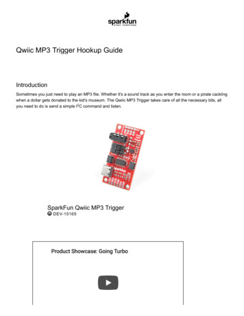
SparkFun Qwiic Digital Temperature Sensor - TMP102 Hookup GuideIntroductionWe all like to know the temperature, right? Well, with the SparkFun Digital Temperature Sensor - TMP102 (Qwiic) we've made this just about as easy as itgets. Based off of the original Digital Temperature Sensor Breakout - TMP102, we've added Qwiic connectors to bring this bad boy into our plug-and-playQwiic Ecosystem, made the board just a bit bigger at 1" x1", and added an address jumper instead of breaking out the address pin. Let's dive in and havesome fun!SparkFun Digital Temperature Sensor - TMP102 (Qwiic) SEN-16304
Product Showcase: SparkFun Qwiic Digital Temperature SensorRequired MaterialsTo follow along with this tutorial, you will need the following materials. You may not need everything though depending on what you have. Add it to yourcart, read through the guide, and adjust the cart as necessary.SparkFun Qwiic Digital Temperature Sensor - TMP102 Wish List SparkFun Wish ListSparkFun Digital Temperature Sensor - TMP102 (Qwiic)SEN-16304Qwiic Cable - 50mmPRT-14426SparkFun RedBoard QwiicDEV-15123Reversible USB A to Reversible Micro-B Cable - 0.8mCAB-15428
Suggested ReadingIf you aren't familiar with the Qwiic system, we recommend reading here for an overview.Qwiic Connect SystemWe would also recommend taking a look at the following tutorials if you aren't familiar with them.I2CAnalog vs. DigitalAn introduction to I2C, one of the main embedded communicationsprotocols in use today.This tutorial covers the concept of analog and digital signals, as theyrelate to electronics.w!NeSerial Terminal BasicsTemperature Sensor ComparisonThis tutorial will show you how to communicate with your serial devicesusing a variety of terminal emulator applications.A comparison of analog and digital temperature sensors. Which is better?
Hardware OverviewTMP102Have you heard the phrase "Good things come in small packages"? Well, here's is a prime example! This board centers around Texas Instruments'TMP102 Low-Power Digital Temperature Sensor. This tiny little chip measures 1.6-mm 1.6-mm and packs quite a nice punch. Here are some of thehighlights, but feel free to check out the Datasheet for more information.Highlights:Uses the I2C interface12-bit, 0.0625 C resolutionTypical temperature accuracy of 0.5 CSupports up to four TMP102 sensors on the I2C bus at a timePowerIdeally, power will be supplied via the Qwiic connectors on either side of the board. Alternatively, power can be supplied through the header along thebottom side of the board labeled 3V3 and GND . The input voltage range should be between 1.4-3.6V. Note: There is no onboard voltage regulation on this boards. If you choose to provide power via the plated through holes, ensure that yourvoltage does not exceed the 4V absolute maximum.
Qwiic ConnectorsOur Qwiic Ecosystem makes sensors pretty much plug and play. There are two Qwiic connectors on either side of the Qwiic Temperature Sensor TMP102 board to provide power and I2C connectivity simultaneously.The I2C address of the board is 0x48 by default , but has 3 other addresses the board can be configured to use.2
I2C PinsThe I2C pins break out the functionality of the Qwiic connectors. Depending on your application, you can connect to these pins via the plated throughholes for SDA and SCL.Alert PinThe alert pin is an over temperature alert, which has an open-drain and is pulled up through a 10kΩ resistor. The alert can also be read over I2C asshown in the example in the Software Setup and Programming section.
JumpersI2C JumpersLike most (if not all) of our Qwiic boards, the TMP102 Temperature Sensor comes equipped with a pull-up resistor. If you are daisy-chaining multipleQwiic devices, you will want to cut this jumper; if multiple sensors are connected to the bus with the pull-up resistors enabled, the parallel equivalentresistance will create too strong of a pull-up for the bus to operate correctly. As a general rule of thumb, disable all but one pair of pull-up resistors ifmultiple devices are connected to the bus. To disable the pull up resistors, use an X-acto knife to cut the joint between the two jumper pads highlightedbelow.
ADDR JumpersThe default I2C address of the board is 0x48. To change the address, cut the jumper connecting the two pads closest to the 0x48 label. Soldering one ofthe center pads to one of the outer most pads will change the boards address to the matching label. The TMP102's address is determined by connectingthe address pin directly to one of the following:ADDR AddressGND0x483V30x49SDA0x4ASCL0x4B
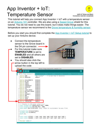
LED JumpersCutting this jumper will disable the Power LED on the front of the board.Board Dimensions
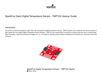
Click on the image for a closer viewHardware AssemblyWith the Qwiic ecosystem, getting up and running is easy! Just plug one end of your Qwiic cable into your TMP102 sensor and the other into the Qwiicport on your RedBoard Qwiic. Voila! You're ready to sense some temperatures!Click the image for a closer view.Software Setup and ProgrammingNote: This code/library has been written and tested on Arduino IDE version 1.8.10. Otherwise, make sure you are using the latest stable version ofthe Arduino IDE on your desktop.If this is your first time using Arduino, please review our tutorial on installing the Arduino IDE. If you have not previously installed an Arduino library,please check out our installation guide.
The Qwiic version of this board uses the same Arduino library as the original board. You can obtain this library through the Arduino Library Manager bysearching for SparkFun TMP102. If you prefer downloading libraries manually, you can grab it from the GitHub Repository.TMP102 ARDUINO LIBRARY (ZIP)Once the library is installed, open Arduino, and expand the examples menu. You should see the TMP102 example.TMP102 Library OverviewMain functionsThese are functions used to read settings and temperatures from the sensor.bool begin( uint8 t deviceAddress, TwoWire &wirePort ) - Takes the device address and I2C bus as optional inputs. If left blank, this functionuses the default address 0x48, and uses the Wire bus.float readTempC( void ) - Returns the current temperature in Celsius.float readTempF( void ) - Returns the current temperature in Fahrenheit.float readLowTempC( void ) - Reads T LOW register in Celsius.float readHighTempC( void ) - Reads T HIGH register in Celsius.float readLowTempF( void ) - Reads T LOW register in Fahrenheit.float readHighTempC( void ) - Reads T HIGH register in Fahrenheit.void sleep( void ) - Put TMP102 in low power mode ( 0.5 uA).void wakeup( void ) - Return to normal power mode ( 10 uA). When the sensor powers up, it is automatically running in normal power mode,and only needs to be used after * sleep() is used.bool alert( void ) - Returns the state of the Alert register. The state of the register is the same as the alert pin.void setLowTempC(float temperature) - Sets T LOW (in Celsius) alert threshold.void setHighTempC(float temperature) - Sets T HIGH (in Celsius) alert threshold.
void setLowTempF(float temperature) - Sets T LOW (in Fahrenheit) alert threshold.void setHighTempF(float temperature) - Sets T HIGH (in Fahrenheit) alert threshold.void setConversionRate(uint8 t rate) - Sets the temperature reading conversion rate. 0: 0.25Hz, 1: 1Hz, 2: 4Hz (default), 3: 8Hz.void setExtendedMode(bool mode) - Enable or disable extended mode. 0: disabled (-55C to 128C), 1: enabled (-55C to 150C).void setAlertPolarity(bool polarity) - Sets the polarity of the alert. 0: active LOW, 1: active HIGHvoid setFault(uint8 t faultSetting) - Sets the number of consecutive faults before triggering alert. 0: 1 fault, 1: 2 faults, 2: 4 faults, 3: 6 faults.void setAlertMode(bool mode) - Sets the type of alert. 0: Comparator Mode (Active from when temperature T HIGH until temperature T LOW), 1: Thermostat mode (Active from when temperature T HIGH until any read operation occurs.Example CodeOnce the library is installed, open the example code to get started! Make sure to select your board and COM port before hitting upload to beginexperimenting with the temperature sensor.
*****************************TMP102 example.inoExample for the TMP102 I2C Temperature SensorAlex Wende @ SparkFun ElectronicsApril 29th 2016 This sketch configures the TMP102 temperature sensor and prints thetemperature and alert state (both from the physical pin, as well as byreading from the configuration register.Resources:Wire.h (included with Arduino IDE)SparkFunTMP102.hDevelopment environment specifics:Arduino 1.0 This code is beerware; if you see me (or any other SparkFun employee) atthe local, and you've found our code helpful, please buy us a round!Distributed as-is; no warranty is **********************************/// Include the SparkFun TMP102 library.// Click here to get the library: http://librarymanager/All#SparkFun TMP102#include Wire.h // Used to establied serial communication on the I2C bus#include SparkFunTMP102.h // Used to send and recieve specific information from our sensor// Connections// VCC 3.3V// GND GND// SDA A4// SCL A5const int ALERT PIN A3;TMP102 sensor0;void setup() {
Serial.begin(115200);Wire.begin(); //Join I2C BuspinMode(ALERT PIN,INPUT);// Declare alertPin as an input/* The TMP102 uses the default settings with the address 0x48 using Wire.Optionally, if the address jumpers are modified, or using a different I2C bus,these parameters can be changed here. E.g. sensor0.begin(0x49,Wire1)It will return true on success or false on failure to communicate. */if(!sensor0.begin()){Serial.println("Cannot connect to TMP102.");Serial.println("Is the board connected? Is the device ID correct?");while(1);}Serial.println("Connected to TMP102!");delay(100);// Initialize sensor0 settings// These settings are saved in the sensor, even if it loses power// set the number of consecutive faults before triggering alarm.// 0-3: 0:1 fault, 1:2 faults, 2:4 faults, 3:6 faults.sensor0.setFault(0); // Trigger alarm immediately// set the polarity of the Alarm. (0:Active LOW, 1:Active HIGH).sensor0.setAlertPolarity(1); // Active HIGH// set the sensor in Comparator Mode (0) or Interrupt Mode (1).sensor0.setAlertMode(0); // Comparator Mode.// set the Conversion Rate (how quickly the sensor gets a new reading)//0-3: 0:0.25Hz, 1:1Hz, 2:4Hz, 3:8Hzsensor0.setConversionRate(2);//set Extended Mode.//0:12-bit Temperature(-55C to 128C) 1:13-bit Temperature(-55C to 150C)sensor0.setExtendedMode(0);
//set T HIGH, the upper limit to trigger the alert onsensor0.setHighTempF(82.0); // set T HIGH in F//sensor0.setHighTempC(29.4); // set T HIGH in C//set T LOW, the lower limit to shut turn off the alertsensor0.setLowTempF(81.0); // set T LOW in F//sensor0.setLowTempC(26.67); // set T LOW in C}void loop(){float temperature;boolean alertPinState, alertRegisterState;// Turn sensor on to start temperature measurement.// Current consumtion typically 10uA.sensor0.wakeup();// read temperature datatemperature sensor0.readTempF();//temperature sensor0.readTempC();// Check for AlertalertPinState digitalRead(ALERT PIN); // read the Alert from pinalertRegisterState sensor0.alert();// read the Alert from register// Place sensor in sleep mode to save power.// Current consumtion typically 0.5uA.sensor0.sleep();// Print temperature and alarm stateSerial.print("Temperature: ");Serial.print(temperature);Serial.print("\tAlert Pin: rt Register: ");Serial.println(alertRegisterState);
delay(1000);// Wait 1000ms}Troubleshooting Need help?If your product is not working as you expected or you need technical assistance or information, head on over to the SparkFun Technical Assistancepage for some initial troubleshooting.If you don't find what you need there, the SparkFun Forums are a great place to find and ask for help. If this is your first visit, you'll need to create aForum Account to search product forums and post questions.Resources and Going FurtherWant more information on the Qwiic TMP102? Check out these links!Schematic (PDF)Eagle Files (ZIP)Datasheet (PDF)Qwiic Info PageArduino LibraryGitHub Hardware RepoSFE Product ShowcaseNeed more inspiration? Check out our Qwiic line of products:Qwiic Accelerometer (MMA8452Q) Hookup GuideTFMini - Micro LiDAR Module (Qwiic) Hookup Guide
Freescale’s MMA8452Q is a smart, low-power, three-axis, capacitivemicro-machined accelerometer with 12-bits of resolution. It’s perfect forany project that needs to sense orientation or motion. We’ve taken thataccelerometer and stuck it on a Qwiic-Enabled breakout board to makeinterfacing with the tiny, QFN package a bit easier.The TFMini is a ToF (Time of Flight) LiDAR sensor capable of measuringthe distance to an object as close as 30 cm and as far as 12 meters! TheTFMini allows you to easily integrate LiDAR into applications traditionallyreserved for smaller sensors such as the SHARP GP-series infraredrangefinders. With the added Qwiic feature, you can quickly connect to thesensor via I2C!Three Quick Tips About Using U.FLQwiic Atmospheric Sensor (BME280) Hookup GuideQuick tips regarding how to connect, protect, and disconnect U.FLconnectors.Measure temperature, humidity, barometric pressure with the SparkFunAtmospheric Sensor Breakout BME280 (Qwiic).
SparkFun Digital Temperature Sensor - TMP102 (Qwiic) SEN-16304. SparkFun Qwiic Digital Temperature Sensor - TMP102 W ish List SparkFun Wish List . Note: This code/library has been written and tested on Arduino IDE version 1.8.10. Otherwise, make sure you are using the latest stable version of