Transcription
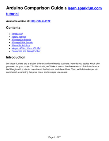
Introduction to ArduinoSparkFun Electronics Summer SemesterInstalling ArduinoMac platform1. Double click the file arduino-0022.dmginside the folder \SIK Applications\Mac\PC platform1. Unzip the file arduino-0022 inside thefolder \SIK Applications\PC\. We recommendunzipping to your c:\Program Files\ directory.2. Go to “Arduino” in the devices section ofthe finder and move the “Arduino” application 2. Open the folder containing your unzippedto the “Applications” folder.Arduino files and create a shortcut toArduino.exe. Place this on your desktop for3. Go to the “Arduino” device, double clickeasy access.and install:“FTDI drivers for Intel Macs 0022.pkg”3. Plug your Arduino board into a free USBorport using the USB cord provided. Wait for a“FTDI drivers for PPC Macs 0022.pkg”pop up box about installing drivers.then Restart your computer.4. Skip “searching the internet”. Click “Install4. Plug your Arduino board into a free USBfrom a list or specific location” in theport using the USB cord provided.advanced section. Choose the locationc:\program files\arduino-0022\drivers\ArduinoUno\(You may have to do this last step morethan once)(If you are using the Duemilanove you willhave to choose the sub-directory, FTDIUSB Drivers and you will have to do thistwice)Issues with Java? Make sure you have the latest version of Java installed.Otherwise.Ta da! You're ready to open the Arduino programming environment.(For Linux info go to http://ardx.org/LINU) 2011 SparkFun Electronics, Inc. SparkFun Electronics Educational Materials are Licensed under Creative Commons Attribution -ShareAlike, CC BY-SASparkFun Electronics Summer Semester is a trademark of SparkFun Electronics, Inc. All other trademarks contained herein are the property of their respective owners.SparkFun Electronics Summer Semester Educational Material
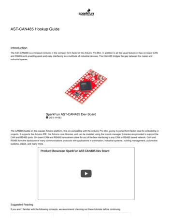
Introduction to ArduinoSparkFun Electronics Summer SemesterA few notes about Arduino setupSelecting your board:You are using the Arduino Uno board with an ATmega 328 micro-controller. This meansyou will need to select “Arduino Uno” as your board. To do this you click on the “Tools” menutab, then click the “Board” tab and select “Arduino Uno”. If you are using a different board youwill need to select the correct model in order to properly upload to your board.Selecting your com port:Another option that is necessary to change occasionally is your “Serial Port”. This canalso be found under the “Tools” menu tab. When you click on this tab you should be presentedwith at least one com port labeled “COM1” (or “COM2, etc.) This indicates which USB portyour board is plugged into. Sometimes you will need to make sure you are using the correct comports for your Arduino, here is some information on your com ports depending on which platformyou are using:MacPCThe Mac version of Arduino refreshes your comport list every time you plug in a device. For thisreason all you really need to do is select the comport called “/dev/cu.usbserial-XXXX” where XXXXwill be a value that changes.The PC version of Arduino creates a new comport for every distinct board you plug into yourcomputer. You will need to find out which comport is the board you are currently trying to use.This is likely to be COM3 or higher (COM1 andCOM2 are usually reserved for hardware serialports). To find out, you can disconnect yourArduino board and re-open the menu; the entrythat disappears should be the Arduino board.Reconnect the board and select that serial port.A few more tidbits that will help to know.There are seven buttons that look like this at the top of your Arduino window:CompileStopHere is what they do from left to right:NewOpenSaveThis checks This stops This createsyour code for the program.a newerrors.sketch.This opensan existingsketch.This savesthe opensketch.UploadSerial MonitorThisUsed to displayuploads theSerialsketch toCommunication.your board.For any words or phrases you are unfamiliar with try the Glossary in the back. 2011 SparkFun Electronics, Inc. SparkFun Electronics Educational Materials are Licensed under Creative Commons Attribution -ShareAlike, CC BY-SASparkFun Electronics Summer Semester is a trademark of SparkFun Electronics, Inc. All other trademarks contained herein are the property of their respective owners.SparkFun Electronics Summer Semester Educational Material
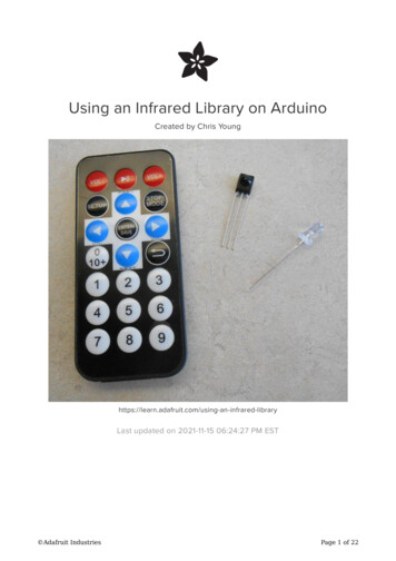
Introduction to ArduinoSparkFun Electronics Summer SemesterBasic Arduino Reference SheetInstallation: Arduino: http://www.arduino.cc/en/Guide/HomePageSupport: Arduino: http://www.arduino.cc, http://www.freeduino.org, google.comForums: Arduino: http://forum.sparkfun.com/viewforum.php?f 32Basic Arduino code definitions:setup( ): A function present in every Arduino sketch. Run once before the loop( ) function. Oftenused to set pinmode to input or output. The setup( ) function looks like:void setup( ){//code goes here}loop( ): A function present in every single Arduino sketch. This code happens over and overagain. The loop( ) is where (almost) everything happens. The one exception to this is setup( )and variable declaration. ModKit uses another type of loop called “forever( )” which executesover Serial. The loop( ) function looks like:void loop( ) {//code goes here}input: A pin mode that intakes information.output: A pin mode that sends information.HIGH: Electrical signal present (5V for Uno). Also ON or True in boolean logic.LOW: No electrical signal present (0V). Also OFF or False in boolean logic.digitalRead: Get a HIGH or LOW reading from a pin already declared as an input.digitalWrite: Assign a HIGH or LOW value to a pin already declared as an output.analogRead: Get a value between or including 0 (LOW) and 1023 (HIGH). This allows you toget readings from analog sensors or interfaces that have more than two states.analogWrite: Assign a value between or including 0 (LOW) and 255 (HIGH). This allows you toset output to a PWM value instead of just HIGH or LOW.PWM: Stands for Pulse-Width Modulation, a method of emulating an analog signal through adigital pin. A value between or including 0 and 255. Used with analogWrite.Arduino Uno pin type definitions: (Take a look at your Arduino board)Reset3v35vGndVinAnalog In RX/TXDigitalPWM( )AREFResetsArduinosketchonboardDigitalpins withoutputoption ofPWMExternalreferencevoltageused foranalog3.3voltsinandout5Ground Voltagevoltsin forinsourcesandover 7V(9V - 12V)outAnaloginputs, canalso beused asDigitalSerialcomm.ReceiveandTransmitInput oroutput,HIGH orLOW 2011 SparkFun Electronics, Inc. SparkFun Electronics Educational Materials are Licensed under Creative Commons Attribution -ShareAlike, CC BY-SASparkFun Electronics Summer Semester is a trademark of SparkFun Electronics, Inc. All other trademarks contained herein are the property of their respective owners.SparkFun Electronics Summer Semester Educational Material
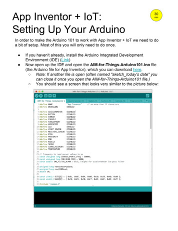
Introduction to ArduinoSparkFun Electronics Summer SemesterBasic Arduino Pin Reference SheetThese boards below use the same micro-controller, just in a different package.The Lilypad is designed for use with conductive thread instead of wire and the ArduinoMini is simply a smaller package without the USB, Barrel Jack and Power Outs. Otherboards in the Arduino family can be found at http://arduino.cc/en/Main/Hardware. 2011 SparkFun Electronics, Inc. SparkFun Electronics Educational Materials are Licensed under Creative Commons Attribution -ShareAlike, CC BY-SASparkFun Electronics Summer Semester is a trademark of SparkFun Electronics, Inc. All other trademarks contained herein are the property of their respective owners.SparkFun Electronics Summer Semester Educational Material
Introduction to ArduinoSparkFun Electronics Summer SemesterAnalogA continuous stream of information with values between and including 0% and 100%.Humans perceive the world in analog. Everything we see and hear is a continuoustransmission of information to our senses. The temperatures we perceive are never 100% hot or100% cold, they are constantly changing between our ranges of acceptable temperatures. (Andif they are out of our range of acceptable temperatures then what are we doing there?) Thiscontinuous stream is what defines analog data. Digital information, the complementary conceptto Analog, estimates analog data using only ones and zeros.In the world of Arduino an Analog signal is simply a signal that can be HIGH (on), LOW(off) or anything in between these two states. This means an Analog signal has a voltage valuethat can be anything between 0V and 5V (unless you mess with the Analog Reference pin).Analog allows you to send output or receive input about devices that run at percentages as wellas on and off. The Arduino does this by sampling the voltage signal sent to these pins andcomparing it to a voltage reference signal (5V). Depending on the voltage of the Analog signalwhen compared to the Analog Reference signal the Arduino then assigns a numerical value tothe signal somewhere between 0 (0%) and 1023 (100%). The digital system of the Arduino canthen use this number in calculations and sketches.To receive Analog Input the Arduino uses Analog pins # 0 - # 5. These pins are designedfor use with components that output Analog information and can be used for Analog Input.There is no setup necessary, and to read them use the command:analogRead(pinNumber);where pinNumber is the Analog In pin to which the the Analog component is connected. TheanalogRead command will return a number including or between 0 and 1023.The Arduino also has the capability to output a digital signal that acts as an Analogsignal, this signal is called Pulse Width Modulation (PWM). Digital Pins # 3, # 5, # 6, # 9, # 10and #11 have PWM capabilities. To output a PWM signal use the command:analogWrite(pinNumber, value);where pinNumber is a Digital Pin with PWM capabilities and value is a number between 0 (0%)and 255 (100%). On the Arduino UNO PWM pins are signified by a sign. For more informationon PWM see the PWM worksheets or S.I.K. circuit 12.Examples of Analog:Values: Temperature, volume level, speed, time, light, tide level, spiciness, the list goes on.Sensors: Temperature sensor, Photoresistor, Microphone, Turntable, Speedometer, etc.Things to remember about Analog:Analog Input uses the Analog In pins, Analog Output uses the PWM pinsTo receive an Analog signal use: analogRead(pinNumber);To send a PWM signal use: analogWrite(pinNumber, value);Analog Input values range from 0 to 1023 (1024 values because it uses 10 bits, 210)PWM Output values range from 0 to 255 (256 values because it uses 8 bits, 28) 2011 SparkFun Electronics, Inc. SparkFun Electronics Educational Materials are Licensed under Creative Commons Attribution -ShareAlike, CC BY-SASparkFun Electronics Summer Semester is a trademark of SparkFun Electronics, Inc. All other trademarks contained herein are the property of their respective owners.SparkFun Electronics Summer Semester Educational Material
Introduction to ArduinoSparkFun Electronics Summer SemesterDigitalAn electronic signal transmitted as binary code that can be either the presence or absence ofcurrent, high and low voltages or short pulses at a particular frequency.Humans perceive the world in analog, but robots, computers and circuits use Digital. Adigital signal is a signal that has only two states. These states can vary depending on the signal,but simply defined the states are ON or OFF, never in between.In the world of Arduino, Digital signals are used for everything with the exception ofAnalog Input. Depending on the voltage of the Arduino the ON or HIGH of the Digital signal willbe equal to the system voltage, while the OFF or LOW signal will always equal 0V. This is afancy way of saying that on a 5V Arduino the HIGH signals will be a little under 5V and on a3.3V Arduino the HIGH signals will be a little under 3.3V.To receive or send Digital signals the Arduino uses Digital pins # 0 - # 13. You may alsosetup your Analog In pins to act as Digital pins. To set up Analog In pins as Digital pins use thecommand:pinMode(pinNumber, value);where pinNumber is an Analog pin (A0 – A5) and value is either INPUT or OUTPUT. To setupDigital pins use the same command but reference a Digital pin for pinNumber instead of anAnalog In pin. Digital pins default as input, so really you only need to set them to OUTPUT inpinMode. To read these pins use the command:digitalRead(pinNumber);where pinNumber is the Digital pin to which the Digital component is connected. The digitalReadcommand will return either a HIGH or a LOW signal. To send a Digital signal to a pin use thecommand:digitalWrite(pinNumber, value);where pinNumber is the number of the pin sending the signal and value is either HIGH or LOW.The Arduino also has the capability to output a Digital signal that acts as an Analogsignal, this signal is called Pulse Width Modulation (PWM). Digital Pins # 3, # 5, # 6, # 9, # 10and #11 have PWM capabilities. To output a PWM signal use the command:analogWrite(pinNumber, value);where pinNumber is a Digital Pin with PWM capabilities and value is a number between 0 (0%)and 255 (100%). For more information on PWM see the PWM worksheets or S.I.K. circuit 12.Examples of Digital:Values: On/Off, Men's room/Women's room, pregnancy, consciousness, the list goes on.Sensors/Interfaces: Buttons, Switches, Relays, CDs, etc.Things to remember about Digital:Digital Input/Output uses the Digital pins, but Analog In pins can be used as DigitalTo receive a Digital signal use: digitalRead(pinNumber);To send a Digital signal use: digitalWrite(pinNumber, value);Digital Input and Output are always either HIGH or LOW 2011 SparkFun Electronics, Inc. SparkFun Electronics Educational Materials are Licensed under Creative Commons Attribution -ShareAlike, CC BY-SASparkFun Electronics Summer Semester is a trademark of SparkFun Electronics, Inc. All other trademarks contained herein are the property of their respective owners.SparkFun Electronics Summer Semester Educational Material
Introduction to ArduinoSparkFun Electronics Summer SemesterInput SignalsA signal entering an electrical system, in this case a micro-controller. Input to the Arduino pinscan come in one of two forms; Analog Input or Digital Input.Analog Input enters your Arduino through the Analog In pins # 0 - # 5. These signalsoriginate from analog sensors and interface devices. These analog sensors and devices usevoltage levels to communicate their information instead of a simple yes (HIGH) or no (LOW). Forthis reason you cannot use a digital pin as an input pin for these devices. Analog Input pins areused only for receiving Analog signals. It is only possible to read the Analog Input pins so thereis no command necessary in the setup( ) function to prepare these pins for input. To readthe Analog Input pins use the command:analogRead(pinNumber);where pinNumber is the Analog Input pin number. This function will return an Analog Inputreading between 0 and 1023. A reading of zero corresponds to 0 Volts and a reading of 1023corresponds to 5 Volts. These voltage values are emitted by the analog sensors and interfaces.If you have an Analog Input that could exceed Vcc .5V you may change the voltage that 1023corresponds to by using the Aref pin. This pin sets the maximum voltage parameter your AnalogInput pins can read. The Aref pin's preset value is 5V.Digital Input can enter your Arduino through any of the Digital Pins # 0 - # 13. DigitalInput signals are either HIGH (On, 5V) or LOW (Off, 0V). Because the Digital pins can be usedeither as input or output you will need to prepare the Arduino to use these pins as inputs in yoursetup( )function. To do this type the command:pinMode(pinNumber, INPUT);inside the curly brackets of the setup( ) function where pinNumber is the Digital pin numberyou wish to declare as an input. You can change the pinMode in the loop( )function if youneed to switch a pin back and forth between input and output, but it is usually set in the setup()function and left untouched in the loop( )function. To read the Digital pins as inputs use:digitalRead(pinNumber);where pinNumber is the Digital Input pin number.Input can come from many different devices, but each device's signal will be eitherAnalog or Digital, it is up to the user to figure out which kind of input is needed, hook up thehardware and then type the correct code to properly use these signals.Things to remember about Input:Input is either Analog or Digital, make sure to use the correct pins depending on type.To take an Input reading use analogRead(pinNumber); (for analog)Or digitalRead(pinNumber); (for digital)Digital Input needs a pinMode command such as pinMode(pinNumber, INPUT);Analog Input varies from 0 to 1023Digital Input is always either HIGH or LOWExamples of Input:Push Buttons, Potentiometers, Photoresistors, Flex Sensors 2011 SparkFun Electronics, Inc. SparkFun Electronics Educational Materials are Licensed under Creative Commons Attribution -ShareAlike, CC BY-SASparkFun Electronics Summer Semester is a trademark of SparkFun Electronics, Inc. All other trademarks contained herein are the property of their respective owners.SparkFun Electronics Summer Semester Educational Material
Introduction to ArduinoSparkFun Electronics Summer SemesterOutput SignalsA signal exiting an electrical system, in this case a micro-controller.Output to the Arduino pins is always Digital, however there are two different types ofDigital Output; regular Digital Output and Pulse Width Modulation Output (PWM). Output is onlypossible with Digital pins # 0 - # 13. The Digital pins are preset as Output pins, so unless thepin was used as an Input in the same sketch, there is no reason to use the pinMode commandto set the pin as an Output. Should a situation arise where it is necessary to reset a Digital pin toOutput from Input use the command:pinMode(pinNumber, OUTPUT);where pinNumber is the Digital pin number set as Output. To send a Digital Output signal usethe command:digitalWrite(pinNumber, value);where pinNumber is the Digital pin that is outputting the signal and value is the signal. Whenoutputting a Digital signal value can be either HIGH (On) or LOW (Off).Digital Pins # 3, # 5, # 6, # 9, # 10 and #11 have PWM capabilities. This means you canOutput the Digital equivalent of an Analog signal using these pins. To Output a PWM signal usethe command:analogWrite(pinNumber, value);where pinNumber is a Digital Pin with PWM capabilities and value is a number between 0 (0%)and 255 (100%). For more information on PWM see the PWM worksheets or S.I.K. circuit 12.Output can be sent to many different devices, but it is up to the user to figure out whichkind of Output signal is needed, hook up the hardware and then type the correct code toproperly use these signals.Things to remember about Output:Output is always DigitalThere are two kinds of Output: regular Digital or PWM (Pulse Width Modulation)To send an Output signal use analogWrite(pinNumber, value); (for analog) ordigitalWrite(pinNumber, value); (for digital)Output pin mode is set using the pinMode command: pinMode(pinNumber,OUTPUT);Regular Digital Output is always either HIGH or LOWPWM Output varies from 0 to 255Examples of Output:Light Emitted Diodes (LED's), Piezoelectric Speakers, Servo Motors 2011 SparkFun Electronics, Inc. SparkFun Electronics Educational Materials are Licensed under Creative Commons Attribution -ShareAlike, CC BY-SASparkFun Electronics Summer Semester is a trademark of SparkFun Electronics, Inc. All other trademarks contained herein are the property of their respective owners.SparkFun Electronics Summer Semester Educational Material
Introduction to ArduinoSparkFun Electronics Summer SemesterCircuit 1Explanation:Schematic:This circuit takes electricity from digital Pin # 9on the Arduino. Pin # 9 on the Arduino has PulseWidth Modulation capability allowing the user tochange the brightness of the LED when usinganalogWrite. The LED is connected to the circuitso electricity enters through the anode ( , orlonger wire) and exits through the cathode (-, orshorter wire). The resistor dissipates current sothe LED does not draw current above themaximum rating and burn out. Finally theelectricity reaches ground, closing the circuit andallowing electricity to flow from power source toground.Components:Arduino Digital Pin # 9: Power source, PWM (ifcode uses analogWrite) or digital (if code usesdigitalWrite) output from Arduino board.LED: As in other diodes, current flows easily fromthe side, or anode (longer wire), to the - side, orcathode (shorter wire), but not in the reversedirection. Also lights up!330 Ohm Resistor: A resistor resists the currentflowing through the circuit. In this circuit theresistor reduces the current so the LED does notburn out.Code:int ledPin 3;void setup() {pinMode(ledPin, OUTPUT);}void loop() {digitalWrite(ledPin,delay(1000); // waitdigitalWrite(ledPin,delay(1000); // waitHIGH); //LED onsecondLOW); //LED offsecond}or for PWM output loop could read :int ledPin 3;void setup() {pinMode(ledPin, OUTPUT);}void loop() {analogWrite(ledPin, 255); // LED ondelay(1000); // wait secondanalogWrite(ledPin, 0); // LED offdelay(1000); // wait secondGnd: Ground}This first circuit is the simplest form of output in the kit. You can use the LED to teach both analog and digitaloutput before moving on to more exciting outputs. There is an LED built into your Arduino board which corresponds toDigital Pin # 13. 2011 SparkFun Electronics, Inc. SparkFun Electronics Educational Materials are Licensed under Creative Commons Attribution -ShareAlike, CC BY-SASparkFun Electronics Summer Semester is a trademark of SparkFun Electronics, Inc. All other trademarks contained herein are the property of their respective owners.SparkFun Electronics Summer Semester Educational Material
Introduction to ArduinoSparkFun Electronics Summer SemesterCircuit 2Explanation:Schematic:This circuit takes electricity from Pin # 2through Pin # 9 on the Arduino. The LEDs areconnected to the circuit so electricity entersthrough the anode ( , or longer wire) and exitsthrough the cathode (-, or shorter wire). Theresistor dissipates current so the LEDs do notdraw current above the maximum rating and burnout. Finally the electricity reaches ground, closingthe circuit and allowing electricity to flow frompower source to ground.Components:Arduino Digital Pins # 2 - # 9: Power source, analog (if codeuses analogWrite, only possible on pins 3, 5, 6, & 9) or digital(if code uses digitalWrite) output from Arduino board.LEDs: As in other diodes, current flows easily from the side, or anode (longer wire), to the - side, or cathode (shorterwire), but not in the reverse direction. Also lights up!330 Ohm Resistor: The resistors resist the current flowingthrough the circuit. In this circuit the resistors reduce thecurrent so the LEDs do not burn out.Gnd: GroundCode://this line below declares an arrayint ledPins[ ] {2,3,4,5,6,7,8,9};void setup( ) {//these two lines set Digital Pins # 0// – 8 to outputfor(int i 0; i 8; i ){pinMode(ledPins[i],OUTPUT);}void loop( ) {//these lines turn LEDs on and then offfor(int i 0; i 7; i ){digitalWrite(ledPins[i], HIGH);delay(delayTime);digitalWrite(ledPins[i], LOW);}}The code examples in the S.I.K get a little complicated for the second circuit, but don'tworry, it's just more outputs. Some of the code examples use “for” loops to do something anumber of times, if you're not familiar with “for” look it up because it is a key programmingconcept. 2011 SparkFun Electronics, Inc. SparkFun Electronics Educational Materials are Licensed under Creative Commons Attribution -ShareAlike, CC BY-SASparkFun Electronics Summer Semester is a trademark of SparkFun Electronics, Inc. All other trademarks contained herein are the property of their respective owners.SparkFun Electronics Summer Semester Educational Material
Introduction to ArduinoSparkFun Electronics Summer SemesterCircuit 3Explanation:Schematic:The motor in this circuit takes electricity from 5V on theArduino. The transistor takes electricity from Pin # 9 onthe Arduino. The resistor before the transistor limits thevoltage so the PWM output from the Arduino affects themotor rate properly. The higher the voltage supplied to thebase of the transistor, the more electricity is allowedthrough the motor circuit to ground. If the transistor base isLOW no electricity is allowed through to ground and themotor will not run. Pin # 9 on the Arduino has PWMcapability so it is possible to run the motor at anypercentage. The flyback diode connected close to themotor is simply to protect the motor in the rare case thatelectricity flows from the transistor towards the motor. Thisonly happens if the transistor is shut off suddenly. Finally,after turning the motor and traveling through the forwardbiased transistor, the electricity reaches ground, closingthe circuit and allowing electricity to flow from powersource to ground.Components:Code:Arduino Digital Pin # 9: Signal power source, PWM outputfrom Arduino board.int motorPin 9;Motor: Electric motor, and – connections, convertselectricity to mechanical energy.void setup() {pinMode(motorPin, OUTPUT);}Transistor: A semiconductor which can be used as anamplifier or a switch. In this case the amount of electricitysupplied to the base corresponds to the amount ofelectricity allowed through from the collector to the emitter.void loop() {for (int i 0; i 256; i ){Flyback Diode: As in other diodes, current flows easilyfrom the side, or anode (longer wire), to the - side, orcathode (shorter wire), but not in the reverse direction.10K Ohm Resistor: A resistor resists the current flowing throughthe circuit. In this circuit the resistor acts as a 'pull-down' resistor toground.analogWrite(motorPin, i);delay(50);}} 5V: Five Volt power source.Gnd: GroundThis circuit is great; it teaches about transistors, one of the basic electronic building blocks. 2011 SparkFun Electronics, Inc. SparkFun Electronics Educational Materials are Licensed under Creative Commons Attribution -ShareAlike, CC BY-SASparkFun Electronics Summer Semester is a trademark of SparkFun Electronics, Inc. All other trademarks contained herein are the property of their respective owners.SparkFun Electronics Summer Semester Educational Material
Introduction to ArduinoSparkFun Electronics Summer SemesterCircuit 4Explanation:Schematic:The servo in this circuit takes electricity from5V on the Arduino. Pin # 9 on the Arduinosupplies a PWM signal that sets the position ofthe servo. Each voltage value has a distinctcorrelating position. Finally the electricity reachesground, closing the circuit and allowing electricityto flow from power source to ground.Components:Code:Arduino Digital Pin #9: Signal power source forservo.//include the servo library for use#include Servo.h Servo myservo; //create servo objectint pos 0;Servo: Sets the position of the servo armdepending on the voltage of the signal received. 5V: Five Volt power source.Gnd: Groundvoid setup() {myservo.attach(9);}void loop() {//moves servo from 0 to 180 for(pos 0; pos 180; pos 1) {myservo.write(pos);delay(15);}// moves servo from 180 to 0 for(pos 180; pos 1; pos- 1) {myservo.write(pos);delay(15);}}Remember, this is just slightly more complicated output, same as the motor and LED. 2011 SparkFun Electronics, Inc. SparkFun Electronics Educational Materials are Licensed under Creative Commons Attribution -ShareAlike, CC BY-SASparkFun Electronics Summer Semester is a trademark of SparkFun Electronics, Inc. All other trademarks contained herein are the property of their respective owners.SparkFun Electronics Summer Semester Educational Material
Introduction to ArduinoSparkFun Electronics Summer SemesterCircuit 5Explanation:Schematic:The shift register in this circuit takes electricityfrom 5V on the Arduino. Pin # 2, # 3 and # 4 onthe Arduino supply a digital value. The latch andclock pins are used to allow data into the shiftregister. The shift register sets the eight outputpins to either HIGH or LOW depending on thevalues sent to it via the data pin. The LEDs areconnected to the circuit so electricity entersthrough the anode ( , or longer wire) and exitsthrough the cathode (-, or shorter wire) if the shiftregister pin is HIGH. The resistor dissipatescurrent so the LEDs do not draw current abovethe maximum rating and burn out. Finally theelectricity reaches ground, closing the circuit andallowing electricity to flow from power source toground.Components:Arduino Digital Pin # 2, # 3 and # 4: Signal powersource for data, clock and latch pins on shiftregister.Shift register: Allows usage of eight output pinswith three input pins, a power and a ground. Linkto datasheet.LED: As in other diodes, current flows easily fromthe side, or anode (longer wire), to the - side, orcathode (shorter wire), but not in the reversedirection. Lights up!330 Ohm Resistor: A resistor resists the currentflowing through the circuit. In this circuit theresistor reduces the current so the LED does notburn out. 5V: Five Volt power source.Gnd: GroundCode:int data 2;int clock 3;int latch 4;int ledState 0;const int ON HIGH;const int OFF LOW;void setup() {pinMode(data, OUTPUT);pinMode(clock, OUTPUT);pinMode(latch, OUTPUT);}void loop(){for(int i 0; i 256; i ) {updateLEDs(i);delay(25);}}void updateLEDs(int value) {digitalWrite(latch, LOW);shiftOut(data, clock, MSBFIRST, value);digitalWrite(latch, HIGH);}For more advanced components you will need to read Datasheets to figure out how touse them. Any documentation is good as long as you can get the correct information out of it. 2011 SparkFun Electronics, Inc. SparkFun Electronics Educational Materials are Licensed under Creative Commons Attribution -ShareAlike, CC BY-SASparkFun Electronics Summer Semester is a trademark of SparkFun Electronics, Inc. All other trademarks contained herein are the property of thei
Introduction to Arduino SparkFun Electronics Summer Semester Or . SparkFun Electronics Summer Semester SparkFun Electronics Summer Semester Educational Material . SparkFun Electronics Summer Semester } }