Transcription
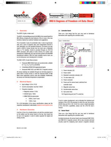
website:6175 Longbow Drive, Suite 200USABoulder, Coloradozip code:80301303284.0979 [ general ]443.0048PFIMU 6 Degrees of Freedom v4 Data Sheet2008.04.221sparkfun.com3.1 Controller BoardOverviewThe 6DOF v3 gets a make-over!The 6DOF v4 Inertial Measurement Unit (IMU) is the newest SparkFunIMU offering, bringing the best features of the v3, plus a few newfunctions inspired by customer feedback and suggestions.There are a few things that the user may want to familiarizethemselves with regarding the controller board.Figure 1: Controller BoardThe v4 provides 3 axes of acceleration data, 3 axes of gyroscopicdata, and 3 axes of magnetic data. Each independent channel isuser selectable, as is the sampling frequency. The device can alsoreport in ASCII or binary format, and can work over a Bluetoothlink or a TTL hardline. Control is provided through an LPC2138ARM7 processor with plenty of extra memory for custom codedevelopment. Additionally, the code has been ported to the WinARMdevelopment platform. With the freely available source code, youcan be doing your own development in minutes!The IMU 6-DOF v4 uses these sensors: Freescale MMA7260Q triple-axis accelerometer, settableto 1.5 g, 2 g, 4 g or 6 g sensitivity 2 InvenSense IDG500 500 degree/second gyros Honeywell HMC1052L and HMC1051Z magnetic sensorsAll sensor readings are available through any terminal program ineither ASCII or binary format, or with the improved 6DOF v4 IMUMixer demo application (source code also available). Additionally,all sensors are internally temperature compensated.1) Power indicator LED2) Power switch3) Bluetooth connection indicator LED4) Tri-color status LED5) Power connector2Electrical Specs Input voltage: 4.2V to 7V DC6) Power port for sensor board, switched fromcontroller board Current consumption: less that 150mA7) Magnetic sense lines Frequency response:8) Accelerometer sense lines Magnetic sensors: 312Hz9) Gyro sense lines IDG500 Gyros: 140Hz10) Programming port and TTL serial line MMA7260Q Accelerometer: 350Hz, X and Y axes 150Hz, Z axisFor a full description of the sensor specifications, please see therespective manufacturer’s data sheets (available at www.Sparkfun.com).3Hardware OverviewLike the v3, the v4 is a double-decker unit with the controller boardon the bottom and the sensor board on the top. Each board hasits own 3.3V regulator in order to better separate the digital andanalog circuits.IMU6-DOF DS v4rev1 080422DataSheet-6DOF-v4-Rev1.indd 1To aid in custom development, we’ve indicated the individual portnumbers of the LPC2138 processor to which the user has access.All ADC lines are 0V to 3.3V, 10-bit. For a more in depth descriptionof the LPC2138’s capabilities, please see the LPC2138 User’smanual.3.2 Sensor BoardThere are a few things that the user may want to familiarizethemselves with regarding the controller board.As stated previously, the sensor board uses Honeywell HMC1052Land HMC1051Z magnetic sensors. We’ve also included set/resetcircuitry (used for realigning each sensor’s magnetic domains1/88/17/09 2:47 PM
2008.04.22IMU 6 Degrees of Freedom v4 Data SheetFigure 2: Sensor Board4.1 Hard line connectionWe’ve provided a back-door to get into the configuration overthe hard line, but first the user needs to establish a hardwareconnection. The easiest way is to use one of our LPC programmingadapters PGM-00714 or PGM-08650, but the user will still needto either solder a female header or the programming adapteritself to the 6DOF v4. We suggest using a header, but if youshould choose to solder directly take care to get the orientationcorrect. All of the signal lines are printed on the respectivePCB’s, so all you need to do is line them up.If you should choose another means of hardware connection,you will need to know that the 6DOF v4 controller board TX andRX lines are 0 to 3.3V, not 5V, and certainly not RS-232. If youconnect the controller board directly to an RS-232 line, you willlikely damage the board.1) Power port2) Magnetic sense lines, plus ser/reset line3) Acceleration sense lines, plus range set lines4) Gyro sense lines5) Vertical-mount gyro port6) Power indicator LEDbefore each measurement), and each channel of the magneticsensors has a high-gain differential amplifier as suggested bythe HMC105X documentation. Supporting components have beenkept at a distance from the sensors so as to increase the accuracyof the measurements.The MMA7260Q accelerometer and the IDG500 gyros have eachbeen set up per their manufacturer’s recommendations, i.e.internal clock suppression filters on their outputs. These sensorsare also internally temperature compensated.All of the sensor lines have been indicated on the PCB should theuser wish to use the 6DOF v4 sensor board with another controlsystem, and all analog outputs are 0V to 3.3V.4SetupWhen you first power up the 6DOF v4, you will see the powerindicator LEDs on both the controller board and the sensor boardlight up. You will also see the tri-color status LED flash a fewtimes. During normal sampling operations, the status LED willtoggle red-blue-green, each color for 64 sample frames. Whenin the configuration menu, all colors will be on. If the device isnot in the configuration menu and not sampling, the 6DOF is inits idle state and the status LED will be off (see the section on theconfiguration menu auto run mode for more details on this).The 6DOF v4 comes pre-configured to run over Bluetooth. But ifyou haven’t got a Bluetooth module IMU6-DOF DS v4rev1 080422DataSheet-6DOF-v4-Rev1.indd 2From this point, we will assume that the user has provided forthe hardware connection and we’ll continue with the setup. Loadyour battery pack and plug it in to the 6DOF (or otherwise applypower to the device). Start with your 6DOF off but connectedto your serial line. Open up a terminal program (Hyperterminal,Teraterm, etc) to the port to which you’re connected withsettings of 115,200 baud, 8 data bits, one stop bit, no parityor flow control. Now simultaneously hold down the spacebaron your keyboard and turn the 6DOF on. You should see theconfiguration menu come up (it will likely scroll past a few timessince the keyboard repeats). Release the spacebar and chooseoption 6 to toggle the output port to “serial TTL”. Cycle power forthe setting to take effect.4.2 Bluetooth connectionGenerally speaking, a Bluetooth discovery will show the 6DOFv4 as “Firefly” with a random MAC. If you’re using a Bluetoothdevice other than what is available from SparkFun, connect tothe 6DOF v4 according to that manufacturer’s directions as aserial port.If you’re using one of the Roving Networks Bluetooth devicesavailable through SparkFun, you can directly open a serial port tothe local device and issue discovery and connection commandswithout the interference of third-party Bluetooth drivers or othersupporting software.The first thing to do is to load your battery pack, plug it intoyour 6DOF v4 and turn it on. Assuming the user has a RovingNetworks Bluetooth dongle (like the BlueDongle-RN-USB),the setup is very simple. Plug in your dongle and open aterminal program to the correct port, set to the same settingsmentioned previously (115,200 baud, etc.). Issue the command“ enter ” and the dongle will answer back with “CMD?”.Then enter the command “I enter ” and the dongle will gooff and search for other Bluetooth devices for a few seconds.When it’s done, it will report to you how many devices it foundand give you their names and MAC addresses. The 6DOF v4 willshow up as “Firefly” with a random MAC address. Now enter thecommand “C, MAC address enter ”, where MAC address is that of the 6DOF v4, and the dongle will answer back with2/88/17/09 2:47 PM
2008.04.22IMU 6 Degrees of Freedom v4 Data Sheet“Trying”. The dongle won’t report the successful connectionwith text in the terminal window, but you’ll see the connectionindicator LED light up on both the 6DOF and the dongle. Nowyou’re connected and ready to run.4.3 6DOF v4 Mixer demo applicationFor a demonstration of the 6DOF v4’s operation, the user canrun the 6DOF v4 Mixer program. With the 6DOF powered up andconnected in its idle state, close any terminal programs, open the6DOF’s serial port and start the mixer application. Select the portnumber to which the 6DOF is connected, set the frequency andsensitivity, hit the start button and you’re off and running.The mixer program requires that all channels are active. If youhave any trouble getting the program to work right, check that allchannels are active in the configuration menu.5Using a Terminal and the ConfigurationMenuOnce the novelty of the mixer program wears off, the user maywant to do something slightly more useful with the v4, like attach itto something and log a file with a terminal program. What followsis a description of the configuration menu as well as a functionaldescription of the v4’s operation.in memory, whereas settings from the actual configuration menuwill be saved to memory for future use. At the same time, all butthe active channel settings saved in memory have no effect onoperation from the idle state. It should be noted that the primarypurpose of this idle state and mode of operation is to more easilyinteract with the v4 mixer demonstration application, but there’sno reason that a user’s own application couldn’t use it for a quicksetup. It should also be noted that the 300Hz sampling rate is notavailable from the mixer app’s selection, the reason being that theBluetooth begins to exhibit latency when streaming data into it atsomewhere between 250Hz and 300Hz with all channels active.But the 300Hz option is available from the idle state in case the userwishes to try it. Of course, operation from the configuration menuhas no maximum setting (more on that later).5.2 Operation from the Configuration MenuTo use the v4 from a terminal program, start up your program ofchoice (115,200 baud, hardware flow control, 8 data bits, one stopbit, no parity), plug in your Blue Dongle and power up your v4. Whenthe devices connect, the Blue Dongle will report the connectionestablished back to you. The v4 is now in the aforementioned idlestate. Pressing the spacebar will bring up the configuration menu(STAT0 and STAT1 will come on as well), and here’s what you’llsee:6DOF v4 setup, version 1.05.1 Operation from the Idle StateUpon reset and in its default configuration, the v4 will check to seeif it has been configured for “auto run” mode (more on that later). Ifit’s not in auto run mode, it goes into an idle state waiting for input.Normally this idle state serves as the start up state for the mixerapplication. In this state, the following inputs have the followingeffects:1) “%”, ASCII 37, sets the accelerometer to 1.5 g sensitivity2) “&”, ASCII 38, sets the accelerometer sensitivity to 2 g3) “ ’ ” (apostrophe), ASCII 39, sets the accelerometersensitivity to 4 g4) “ ( “, ASCII 40, sets the accelerometer sensitivity to 6 g1) View/edit active channellist2) Change output mode,curerntly binary3) Set Auto run mode,curerntly off4) Set accelerometersensitivity, currently 1.5 g5) Set output frequency,currently 1006) Change output port,currently Bluetooth9) Save settings and run unit5) “ ) ”, ASCII 41, sets the sample frequency to 50Hz5.3 Active Channel List6) “ * ”, ASCII 42, sets the sample frequency to 100HzPressing “1” will bring up the active channel list:7) “ ”, ASCII 43, sets the sample frequency to 150Hz1) Magneto X on8) “ , “, ASCII 44, sets the sample frequency to 200Hz2) Magneto Y on9) “ - “, ASCII 45, sets the sample frequency to 250Hz3) Magneto Z on10) “ . ”, ASCII 46, sets the sample frequency to 300Hz11) “#”, ASCII 35, starts the unit running in binary mode withall channels active12) “ “ (space), ASCII 32, stops the unit and returns it to theidle state (issuing another ASCII 32 will bring up theconfiguration menu)Operation from this idle state will always be in binary output mode,but the user may select which channels are active. Also, configurationfrom this state as done in the mixer application will not be savedIMU6-DOF DS v4rev1 080422DataSheet-6DOF-v4-Rev1.indd 34) Accel X on5) Accel Y on6) Accel Z on7) Pitch on8) Roll on9) Yaw onPress the number of the channel you wish tochange,or press x to exit.To change a channel from active to inactive (or the reverse), justpress the number of the channel you wish to change. It’s a toggling3/88/17/09 2:47 PM
2008.04.22IMU 6 Degrees of Freedom v4 Data Sheetfunction; pressing a number will bring up the full list again, butwith the channel you wished to change in its opposite state. Pressa few numbers and get a feel for it. Pressing “x” gets you back tothe main menu.of a Bluetooth connection if the Bluetooth is active. Pressing thespacebar will bring up the configuration menu again.5.4 Output ModePressing “4” from the main menu will bring up the followingsubmenu:Pressing “2” from the main menu will toggle the output mode frombinary to ASCII and back again. What are these output modes, youask?Set to:In both output modes, the data from all active channels is framedby an “A” (ASCII 65) at the start and a “Z” (ASCII 90) at the end. Alsoin both modes, each channel is reported in exactly the sequenceshown in the active channel list, with the addition of a samplecount that immediately follows the “A” and precedes the first activemeasurement, which is to say:1) Count2) Mag X3) Mag Y4) Mag Z5) Accel X6) Accel Y7) Accel Z8) Pitch9) Roll10) YawThe count is two bytes that comes as MSB-LSB, and will range from0 to 32767. If any of the channels are selected as inactive, that datais omitted from the frame and subsequent data moves up in thereport sequence.In binary mode, each active channel report comes as 2 bytes: MSBand LSB, in that sequence, and they will always be between 0 and1023 because we’re reading from 10-bit ADC’s. The width of thedata frame in binary mode will be 4 bytes (“A”, “Z”, and count arealways present) plus 2 bytes for each active measurement. So forall channels active the data frame will be 22 bytes wide.In ASCII mode, the count and active measurements are reportedin ASCII so it’s easier to read with a terminal program, plus allmeasurements and the count are delimited with TAB characters(ASCII 9) as well as a carriage return and line feed at the end ofthe data frame. This makes data capture and importation into aspreadsheet a relatively simple matter.5.5Auto Run ModePressing “3” from the main menu will toggle the auto run setting. Ifyou intend to use the v4 in ASCII mode, set this to “on”. If the autorun feature is off, the v4 will always run from it’s primary idle state,which means that it will always wait for a “#” to begin sampling andit will always run in binary mode.5.6 Setting the Accelerometer Sensitivity1) 1.5g2) 2g3) 4g4) 6gJust press the number which corresponds to your choice and the v4will revert to the main menu with the sensitivity changed.5.7 Setting the Output FrequencyPressing “5” from the main menu will allow you to change thesample frequency. Simply press “i” to increase or “d” to decrease,or “x” to revert to the main menu.The minimum frequency setting is 10Hz, and there is no maximumsetting. This allows the user to experiment with smaller data framesand higher sampling rates.5.8 Setting the output portPressing “6” will allow you to toggle the output port, either Bluetoothor serial TTL. After selecting this option, you will be prompted tocycle power for this setting to become active.5.9 Save Settings and Run UnitPressing “9” from the main menu will save the current settings toflash and exit the configuration menu. If the auto run feature hasbeen activated the unit will begin running immediately. If it has notbeen set, the unit will revert to the initial idle state and wait foradditional input.6Bandwidth Considerations and FirmwareThe 6DOF v4 does not have any filtering in firmware, though thereis enough memory left in the LPC2138 flash program space toimplement some filtering. The internally set output bandwidth ofthe MMA7260Q accelerometer is 350Hz for the X and Y axes, and150Hz for the Z axis. There are also additional single pole low passfilters to reduce switching noise from the sensor with poles set at1591Hz (recommended by Freescale). The internally set outputbandwidth for the IDG300 gyro sensors is 120Hz, along with singlepole low pass filters at 96Hz (recommended by InvenSense). TheHMC1052L and HMC1051Z magnetic sensors don’t have internalfiltering, but each axis has an external single pole low pass filter setat 319Hz. Of course, it’s a good idea for the user to consider thesenumbers when developing an application to ensure that the properfiltering is in place for whatever sampling rate is selected.One feature of auto run mode is that if the setting is active the v4 willbegin sampling immediately upon power up, or after establishmentIMU6-DOF DS v4rev1 080422DataSheet-6DOF-v4-Rev1.indd 44/88/17/09 2:47 PM
2008.04.22IMU 6 Degrees of Freedom v4 Data SheetAll source code and schematics for the 6DOF v4 are freely availablefrom the v4’s product description page. Source code is compiledwith GCC using WinARM (http://www.siwawi.arubi.uni-kl.de/avr projects/arm projects/#winarm). Programming is typicallydone with the SparkFun LPC programming adapter (SKU #’s:PGM-00714 or PGM-08650) and Flash Magic, which is availablefor free download at http://www.flashmagictool.com/. 2007 SparkFun Electronics, Inc. All Rights Reserved. Product features, specifications, system requirements and availability are subject to change without notice. GeoChron is a trademark of SparkFun Electronics, Inc. All othertrademarks contained herein are the property of their respective owners.IMU6-DOF DS v4rev1 080422DataSheet-6DOF-v4-Rev1.indd 55/88/17/09 2:47 PM
2008.04.22IMU 6 Degrees of Freedom v4 Data Sheet4/22/200808:07:01a f 0.68 OF V4\6DOF V4\6DOF V4 2.sch (Sheet: 1/1)IMU6-DOF DS v4rev1 0804226/8DataSheet-6DOF-v4-Rev1.indd 68/17/09 2:47 PM
2008.04.22IMU 6 Degrees of Freedom v4 Data Sheet4/22/2008 08:08:21a f 0.68 OF V4\6DOF V4 Sensor Board\6DOF V4 Sensor BoardIMU6-DOF DS v4rev1 080422DataSheet-6DOF-v4-Rev1.indd 77/88/17/09 2:47 PM
2008.04.22IMU 6 Degrees of Freedom v4 Data Sheet4/22/2008 08:09:02a OF V4\IDG300 Breakout\IDG300 Breakout 2.sch (SheetIMU6-DOF DS v4rev1 080422DataSheet-6DOF-v4-Rev1.indd 88/88/17/09 2:48 PM
website: sparkfun.com zip 80301code: bouLDer, CoLoraDo USA 2 0 0 8 . 0 4 . 2 2 IMU6-DOF_DS_v4rev1_080422 1 Overview the 6DoF v3 gets a make-over! the 6DoF v4 inertial Measurement unit (iMu) is the newest SparkFun iMu offering, bringing the best features of the v3, plus a few new functions inspired by customer feedback and suggestions.