Transcription
L1 and L2 POS Motherboard(with BIOS Setup)User Manual
We would like to know your opinion on this publication.Please send us a copy of this page if you have any constructive criticism.We would like to thank you in advance for your comments.With kind regards,Your opinion:Diebold Nixdorf Systems GmbHWohlrabedamm 31D-13629 BerlinE-Mail: retail.documentation@dieboldnixdorf.comOrder No.: 01750266922C
L1 and L2 POS MotherboardUser ManualEdition November 2018
All brand and product names mentioned in this document are trademarks of theirrespective owners.Copyright Diebold Nixdorf Systems GmbH, 2018The re production, transmission or use of this document or its contents is not permitted withoutexpress authority. Offenders will be liable for damages. All rights, including rights created by patentgrant or registration of a utility model or design, are reserved. Delivery subject to availability; technicalmodifications possible.
ContentsOverview . 1Introduction . 1Some Highlights of the L1 and L2 Motherboard . 1Motherboard Specification . 3Block Diagram . 3Internal Connectors . 4Mainboard assembly variants . 5CPU support . 5Mainboard internal connectors and onboard features . 5USB 2.0 (internal) . 5Mini PCI Express . 6Memory (internal) . 7SATA (internal) . 7Fan (internal) . 7PWM Fan. 8DC Fan . 8Chassis intrusion connector (internal). 8Front panel connector (internal) . 8ATX / 12V Power connector (internal) . 10LPT (internal) . 11TPM (onboard) . 11PCI Express Slots (internal) . 12Use in the systems BEETLE /MIII, EPC 5G, EPC 5G DC orEPC 5G Upgrade . 12Onboard power button and status LED (internal) . 13Mainboard onboard connectors with external access . 13Motherboard I/O shield overview (external) . 13DVI-D (external) . 13VGA (external) . 13LAN (external). 14USB 2.0 / USB 3.0 (external) . 14COM (external) . 14Audio (external) . 14
Technical Data. 15Supported Sleep States . 16RAID (L1 Motherboard) . 17Changing the Battery . 18UEFI BIOS Setup . 18Standard UEFI BIOS Version . 19BIOS Menu Bar . 20Legend Screen . 20General Help. 21Scroll Bar. 21Sub-Menu . 22Info Screen . 22Main Menu . 24Advanced Menu . 25Sub Menu ACPI Settings . 26Sub Menu Trusted Computing . 26Sub Menu Hardware Configuration . 29Sub Menu CPU Configuration. 32Sub Menu SATA Configuration . 35Sub Menu PCH-FW Configuration . 37Sub Menu PCH-FW Configuration Firmware Update Configuration 37Sub Menu AMT Configuration . 38Sub Menu USB Configuration . 40Sub Menu NTC6106D Super IO Configuration . 42Sub Menu NTC6106D Super IO Configuration Parallel PortConfiguration . 42Sub Menu NTC6106D H/W Monitor. 43Sub Menu Serial Port Console Redirection . 44Sub Menu Serial Port Console Redirection Legacy ConsoleRedirection Settings . 44Sub Menu Serial Port Console Redirection Console RedirectionSettings . 45Sub Menu AMI Graphic Output Protocol Policy . 46Sub Menu Network Stack Configuration . 47Sub Menu CMOS . 48
Sub Menu Intel(R) Ethernet Network Connection . 48Sub Menu Intel(R) Ethernet Network Connection NIC Configuration. 49Chipset Menu . 49Sub Menu PCH-IO Configuration . 49Sub Menu PCH-IO Configuration BIOS Security Configuration. 49Sub Menu System Agent (SA) Configuration . 50Sub Menu System Agent (SA) Configuration Graphics Configuration. 50Boot Menu . 52Sub Menu CSM Parameters . 54Security Menu . 55Sub Menu Secure Boot menu. 56Save & Exit Menu . 57Test Points Codes . 58Checkpoint Ranges . 58SEC Phase . 59PEI Phase . 60PEI Beep Codes . 63DXE Phase . 63DXE Beep Codes . 67Abbreviations . 68
OverviewIntroductionThis manual describes the features of two variants of a Motherboardbased on the Intel 8 series chipset Q87 and H81, formerly known as LynxPoint.These L1.x and L2.x Motherboards were primarily designed for the WincorNixdorf Systems EPC 5G, EPC 5G DC and EPC 5G Upgrade.Some Highlights of the L1 and L2 Motherboard 4th Generation Intel Core Processors, formerly known as Haswell Intel 8 series chipset Q87 and H81, formerly known as Lynx Point CPU integrated graphic controller up to Intel HD Graphics 4600,depending on used processor AMT 9.1 support at L1 motherboards 1x VGA Interface 1x DVI-D interface Gigabit LAN onboard (Intel Ethernet Connection; Q87: I217-LM, H81:I217-V) 3 SATA ports (Q87: 3xSATA III, H81: 2x SATA III 1x SATA II) 2x DDR3 SODIMM sockets, supporting up to 16GB (2x8GB) at1600MHz. Only 3GB available for 32bit OS 1x PCI Express x16 gen3 2x PCI Express x1 gen2 2 Standard COM ports 1 LPT port MiniPCIe socket (full size) supporting the WN NVRAM module 2 USB3.0 ports Q87: 12 USB2.0 ports, H81: 8x USB portsL1 and L2 Motherboard, User Manual1
TPM onboard PC Beeper onboardTFT- displays without DDC are not supported.2L1 and L2 Motherboard, User Manual
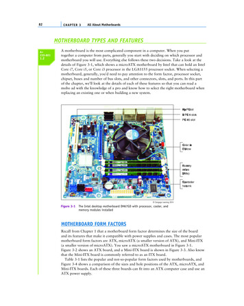
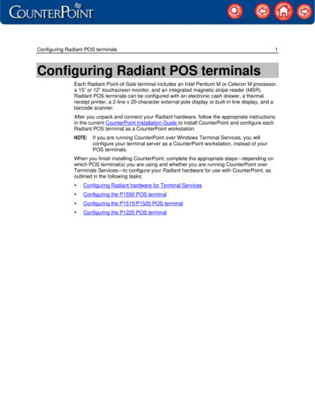
Motherboard SpecificationBlock DiagramL1 and L2 Motherboard, User Manual3
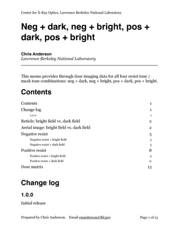
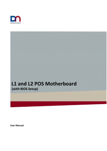
Internal Connectors4L1 and L2 Motherboard, User Manual
Mainboard assembly variantsAs mentioned above there are two motherboard variants: The L1 boardwith Q87 chipset supporting AMT and RAID and the L2 board with H81chipset as value edition supporting lesser features.CPU supportCPUCPU#i5#CPUcore#ThreadsGHzCorei5-4570TE 24i5i5-4570S4i3GHz GFXCachesizeTDP[W]2.7 (3.3) 0.35 (1)4MB3542.9 (3.6) 0.35(1.15)6MB65i3-4330TE 242.40.35 (1)4MB35i3i3-4330243.50.35 (1.15) 4MB54PentiumG3320TE222.30.35 (1)3MB35PentiumG3420223.20.35 (1.15) 3MB53CeleronG1820TE222.20.35 (1)2MB35CeleronG1820222.70.35 (1.05) 2MB53Mainboard internal connectors and onboard featuresUSB 2.0 (internal)6 USB ports at L1 board and 2 USB ports at L2 are routed to 10pin doublerow headers with 2.54 mm pitch. Each header provides 2 ports. Theseheaders are intended to connect optional front USB modules or USB hubs.L1 and L2 Motherboard, User Manual5
Two USB ports share one fuse. USB port 11 at header USB3 (pins 1,3,5,7) isshared with PCIe x1 connector PCIE3 (pins A5 to A8) for USB uplinkconnection for the "Retail Card".Mini PCI ExpressThe mainboard provides a full size mini PCI Express (rev.1.1) / mSATAconnector. It is placed on top, thus being accessable without removingother components. It supports LPC signals including serial interrupts.Auto detection by mSATA presence detect supports automated switchbetween mSATA and PCIe functionality (PCIe functionality only supportedin conjunction with Q87 chipset according to mini PCI Express StandardRev 1.1). The L1 motherboard supports PCIe and mSATA functionality,the L2 motherboard supports mSATA functionality only. Connector type:Standard MiniPCIe 1.1 connector full .6VCC K 14LAD115GND16LAD017SUSCLK 32KHz18GND19CLK 33MHz20n.c.21GND22RESET#23PCIE RX- / SATA B243VSB25PCIE RX / SATA -B26GND27GND28VCC 1.5V29GND30SMB CLK31PCIE TX- / SATA -A32SMB DATA33PCIE TX / SATA A34GNDL1 and L2 Motherboard, User Manual
35GND36n.c. (USB-)37GND38n.c. (USB .c.48VCC 1.5V49n.c.50GND51mSATA presence detect52VCC3Memory (internal)The mainboard provides two DDR3 SODIMM sockets supporting up to16GB in dual channel mode. The horizontal mounting of the SODIMMsockets ensures an optimal air flow.SATA (internal)The mainboard provides three standard SATA ports. The ports SATA1(white) and SATA2 (blue) supporting SATA III connectivity speed.Port SATA3 (black) supports SATA III speed at L1 board, and SATA IIspeed at L2 board. The RAID functionality is only supported by the L1motherboard.Fan (internal)The mainboard provides two fan connectors. The CPU fan connectorsupports PWM fans with 4 pin connection.Connector details are: 2.54mm (.100") Pitch Vertical Header, with FrictionLock, 4 (3) Circuits, PC Tail Length: 3.50mm (.138"). Molex Part Nr: 470531000 or similar. The connector follows the Intel “4-Wire Pulse WidthModulation (PWM) Controlled Fans” specification.L1 and L2 Motherboard, User Manual7
PWM FanPinSignalSignal Description1GNDGND212 VFan operation voltage3SenseTachometric signal4ControlPWM control signal (only4 pin connector)The PSU fan connector has 3 pin connection with DC fan speed regulation.PinSignalSignal Description1GNDGND2PWROperation Voltage 6-12 V3SenseTachometric signalDCFanChassis intrusion connector (internal)The mainboard supports a chassis intrusion connector.Type: 3 pin shrouded header, B3B-PH-K-S (JST) or equivalent.Pin NumberFunction1GND2Intrusion input (switch to GND ifchassis is open)3n.c.Front panel connector (internal)The mainboard supports a front panel connector to support serviceelements (like POWER ON pushbutton, HDD and power LEDs).The Power LED at the chassis front connected to this front panel header isgreen when system is powered on (S0). During Stand By (S3) it blinks greenand when system is in hibernation (S4) or powered down (S5) the LED isorange.8L1 and L2 Motherboard, User Manual
Power StatusPower LEDS0GreenS3Green blinkingS4, S5OrangeThe BIOS is able to disable the power button. This feature is automaticallyenabled when "Follow AC power" is selected within the BIOS setup. Then itis not possible to switch off the system by the power button, even whenpressed longer than 4s. But when the OS is shut down correctly, systemcan be switched on again by the power button.The front panel header also supports speaker connection.Type: 2x6 pin header, 2.54 mm pitch.Pin NumberFunction1Power switch 2Reset switch 3Power switch -4Reset switch -5Power LED 6Speaker -7Power LED -8Coding9HDD LED 10GND11HDD LED -12Speaker L1 and L2 Motherboard, User Manual9
ATX / 12V Power connector (internal)The mainboard provides a 4 pin and a 24 pin ATX power connector.Pin NumberFunction1,2,12,13 3.3V3,5,7,15,17,18,19,24GND4,6,21,22,23 5V8Power ok95V SB10, 11 12V14-12V16PSON20n.c.Pin NumberFunction1,2GND3,4 12VA 20 pin ATX power cable can be plugged into the 24 pin connector on themotherboard, too. In this case the pins 11,12,23 and 24 are not used andleft open. The 4 pin ATX power connector has to be connected to the PSUanyway, otherwise the motherboard will not work.10L1 and L2 Motherboard, User Manual
LPT (internal)Connector type: 26 pin shrouded header, 2.54mm 6GND4ERR#17D75D118GND6PINIT#19ACK#7D220GND8LPT D526KeyTPM (onboard)The mainboard provides a Trusted Platform Module (TPM) IC fromInfineon. The Lx.0 boards provide the SLB 9635TT1.2 with firmware 3.19,the Lx.1 boards the SLB 9660TT1.2 with firmware 4.40. The SLB 9660 isable to be upgraded to TT2.0 by a firmware update. During this update alldata, provisioning, certifications and keys stored within the TPM IC will belost. For identification of the firmware there is an additional identifier inthe POST while the TPM is active:TT1.2 on SLB 9635 has identifier #TPMTT1.2 on SLB 9660 has identifier #TPM1TT2.0 on SLB 9660 has identifier #TPM2The TPM IC is directly soldered on the PCB.L1 and L2 Motherboard, User Manual11
Jumper 4 (JP4):Enables/Disables the TPM Chip. Default setting is position 1-2, TPMenabled. To disable the TPM set Jumper to position 2-3.Jumper 3 (JP3):Sets the physical presents (PP). Default setting is position 2-3, PP disabled.To enable PP set Jumper to position 1-2. TT2.0 is not supporting the PPfeature any more.PCI Express Slots (internal)There are two PCIe slots x1 and one 1 PCIe slot x16.Use in the systems BEETLE /MIII, EPC 5G, EPC 5G DC or EPC 5G UpgradeOnly low profile cards are supported.Height 68.90 mm (2.731 inches) maximum,Length 167.65 mm (6.600 inches) maximumPCIe cards are able to wake up the system.Thermal management: The input power of a single PCIe x1 card must notexceed 10W and x16 card does not exceed 30W.The PCIe slot at the outer side of the mainboard supports USB signals onPCIe pins A5 (D-) and A8 (D ) as USB uplink connection and A6 A7 (VBUS)to Retail specific PCIe card.The same USB port is routed to the USB3 connector.12L1 and L2 Motherboard, User Manual
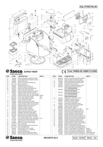
Onboard power button and status LED (internal)The motherboards support one onboard power button in rear I/O shieldarea. The button’s position protects it from being touched accidentallyor being pushed by cables.The motherboards support 2 dual color onboard LEDs indicating the powerstatus (green) and HDD activity (red). The LEDs are visible outside of thechassis through a chassis hole.Power statusPower LEDS0GreenS3, S4, S5OffOnboard status LEDs and power button work together with an externalstatus LED and power button connected to the front panel connector.Mainboard onboard connectors with external accessMotherboard I/O shield overview (external)The picture below shows the arrangement of the onboard I/O connectors.DVI-D (external)This intervace uses a standard DVI-D connector supporting a single linkconnection to a digital display. Only displays with DDC are supported.VGA (external)This interface uses a 15 pin DSUB connector in the upper row of I/O shield.Sync signals VSYNC and HSYNC have 5V logic high level.L1 and L2 Motherboard, User Manual13
LAN (external)The mainboard supports 1Gbit connection to a Local Area Network (LAN).Indication LED for link and activity is available.Right LEDSpeed Indication10mbitoff100mbitgreen1000mbitorangeLeft LEDLink&ActivityLink at every speedYellow onTraffic at every speedYellow blinkingWOL (wake on LAN) and PXE are supported.USB 2.0 / USB 3.0 (external)8 USB ports (6 for USB2.0 and 2 for USB3) are located in the mainboard I/Oconnector area.COM (external)There are two standard RS232 COM por
L1 and L2 POS Motherboard (with BIOS Setup) We would like to know your opinion on this publication. Please send us a copy of this page if you have any constructive criticism. We would like to thank you in ad