Transcription
DIMENSIONING FUNDAMENTALSGraphic entities on drawings describe shape and position. Dimensions and notes describe size, locationand necessary manufacturing and building processes instruction for a fabricator, builder, shoptechnician , etc.
DIMENSIONING FUNDAMENTALSAfter covering this section you will know how to do the following:Use conventional dimensioning techniques to describe size, shape and locations on anengineering drawing.Create and read at a specified scale.Create drawings using metric, engineering and architect scales.Correctly place dimension lines, extension lines, angles and notes.Recognize aligned and unidirectional dimension systems.Dimension circle, arcs and inclined surfaces.Apply finish symbols and notes to a drawing.
We have all heard the “rule of thumb”. At one time, an inch was defined bythe width of a man’s thumb, and a foot, simply was the length of a man’sfoot.THE RULE OF THUMBA FOOTDIMENSIONING FUNDAMENTALS.
DIMENSIONS
neDIMENSION LINES AND EXTENSION LINESDimension Lines: A thin, dark, solid line terminated by arrowheads, which indicatethe direction and extent of a dimension.Extension Lines: A thin, dark solid line that “extends” from a point on the drawing towhich a dimension refers.
LOCATION AND SIZE DIMENSIONS ON A DRAWINGIn addition to drawing a complete shape description of an object, a drawingmust also give complete size and location descriptions.By doing this you are dimensioning the drawing.
LOCATION AND SIZE DIMENSIONS ON A DRAWINGShape description: What does the object look like? The Shape of the object.Size Dimensions: How big or small is something? For example, what is the size of thecircle being drilled through the block? How big is that block, what is it’s size?Location Dimensions: Where should that hole be drilled through the block?
LOCATION AND SIZE DIMENSIONS ON A DRAWING Dimensions on a drawing need to be exact and clear. Dimensions on a drawing should be given so workersbuilding or fabricating the part do not have to assumeanything, measure anything, and dimensions given shouldalways be to points or surfaces accessible to the worker. Dimensions should not be duplicated or excessive. Drafters should be familiar with and understand thematerials used in their parts so they can exercise properjudgment in the engineering matters itself.DON’T MAKE SOMEONE ASSUMEUNDERSTANDTHE PARTDIMENSIONS SHOULD BE EXACT AND CLEARDON’T DUPLICATE OR PUT EXCESSIVE DIMENSIONSDIMENSIONING FUNDAMENTALS.
QUICK TIPS Place the shorterdimensions nearest to theobject outline. Dimension lines shouldNEVER cross extension lines.(This would only happen ifyou placed the shorterdimensions outside of longerdimensions) Be sure to leave a small gapbetween the Extension Lineand the object. Keep dimension line spacingconsistent throughout thedrawing.DIMENSIONING FUNDAMENTALSPLACEMENT OF DIMENSION LINES
QUICK TIPS Line up and groupdimensions as much aspossible so the drawing looksneat and keep spacingconsistent everywhere. Don’t break extension linesaround the object lines. Hold dimension lines off ofthe object. Dimensionsshould only be on the objectin a last resort.DIMENSIONING FUNDAMENTALSPLACEMENT OF DIMENSION LINES
QUICK TIPS Stagger dimension values whenthey are close to make it easier toread. If you dimension within a section,hold the dimension off of theobject or clear the section liningfrom within. Unidirectional system is thepreferred way of includingdimension figures. If a dimension is not to scale aheavy black line will be presentunder it.DIMENSIONING FUNDAMENTALSPLACEMENT OF DIMENSION LINES
LEADER LINES
LEADER LINES AT WORKLEADER LINES
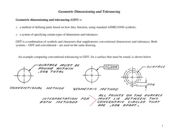
LEADER LINESLeader Lines: A thin, dark, solid line leading from a note or dimension and terminatinginto an arrowhead or dot, touching the part to which the attention is directed.
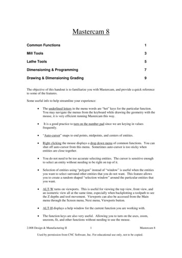
Leader used to describe hole size.Leader used to describe a part.QUICK TIPS A leader to a circle should be radial, that is, ifextended would pass through the center. Leaders drawn near each other should beparallelExamples of Leader Lines in UseLEADER LINES AT WORKLeader used to describe form.
LEADER LINES AT WORKLeader used to describe cuteness.
LEADER LINES AT WORKLeader used to describe cuteness.
FRACTIONAL, DECIMAL, & METRIC DIMENSIONS
In the early days, those who were manufacturing the goods would scale drawings fordimensions and it was their responsibility to see the parts fit. As industry as progressed a greater demand for more accurate dimensions arerequired. It became cumbersome to use 1/128 or 1/256 so decimals began being usedsuch as 4.2340 etc. However some dimensions such as standard nominal sizes ofmaterials, punched holes, drilled holes, threads, keyways and other features producedby tools are so designed to use whole numbers and common fractions. Therefore, drawings can be dimensioned with whole number and common fractions,decimals, or both. But more recent practice was to adopt the decimal-inch systembecause millimeters and inches in the decimal form are easier to add and subtract thanfractions. Millimeters are used on most engineering drawings but to facilitate the changeover tometric dimensions, some drawings are dual-dimensioned in mm and decimal inches.DIMENSIONING FUNDAMENTALSFRACTIONAL, DECIMAL, & METRIC DIMENSIONS
DIMENSIONING ARCS, ANGLES, AND CYLINDERS
There are various ways to dimension arcs, angles, and cylinders. The key isto select the best method for the drawing and keep it consistent.Dimensioning ArcsDimensioning CylindersFillets and Rounds are dimensioned as arcs. If there are onlya few and they are all obviously the same size, one typicalradius note is sufficient and could be dimensioned as “4XR.50” meaning the there are 4 radius at .50. Other notescould be said such as “FILLETS R6 AND ROUNDS R3UNLESS OTHERWISE SPECIFIED”.Dimensioning AnglesDIMENSIONING FUNDAMENTALSDIMENSIONING ARCS, ANGLES, & CYLINDERS
DIMENSIONING HOLES
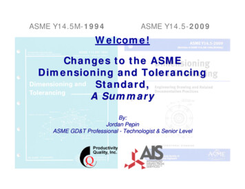
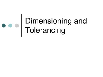
Holes that are drilled, bored, reamed, punched, cored, etc., are specified by symbols.The order of the items in a note corresponds to the order of procedure in the shop inproducing the hole. When the circular view of the hole has two or more concentric circles as for counterbored, countersunk or tapped holes, the arrowhead should touch the outer circle. The leader should point to the circular view of the hole, and only in the rectangularview when it improves clarity.DIMENSIONING FUNDAMENTALSDIMENSIONING HOLES
Holes that are drilled, bored, reamed, punched, cored, etc., are specified by symbols. The order of the items in a notecorresponds to the order of procedure in the shop in producing the hole. When the circular view of the hole has two or more concentric circles as for counter bored, countersunk or tapped holes, thearrowhead should touch the outer circle. The leader should point to the circular view of the hole, and only in the rectangular view when it improves clarity.DIMENSIONING FUNDAMENTALSDIMENSIONING HOLES
DIMENSIONING SYMBOLS
DIMENSIONING FUNDAMENTALSDIMENSIONING SYMBOLSFINISH MARKS (FAO)Finish All Over
DIMENSIONING TERMS
Mating Dimensions: An instances where a feature on a part must fit into or onto another part. The“mating dimension” must be specified in the corresponding locations on the 2 parts so they can begiven the proper fitting of the parts .Superfluous Dimensions: Dimensions that are repeated on the same view or on different views, or thesame information be given in two different ways.General Note: A note that applies to the entire drawingLocal Note: Applies to specific operations only and are connected by a leader to the point. The leadershould be attached to the front of the first word, or at the end of the last word.Taper: A conical surface on a shaft or in a hole. The usual method of dimensioning a taper is to give theamount of taper in a note, such as TAPER 0.167 ON DIA. And then give the diameter at one end, plusthe length, or give the diameter at both ends and omit the length.Knurl: The roughened surface to provide a better handgrip. Often labeled as PITCH 0.8 DIAMOND KNURL.ANSI: stands for the American National Standards InstituteISO: stands for the International Standards OrganizationDIMENSIONING TERMSDIMENSIONING TERMS:
DIMENSIONING FUNDAMENTALSDIMENSIONED DETAIL DRAWING
engineering drawing. Create and read at a specified scale. Create drawings using metric, engineering and architect scales. Correctly place dimension lines, extension lines, angles and notes. Recognize aligned and unidirectional dimension systems. Dimension circle, arcs and inclined surfaces. Appl