Transcription
ME 111: Engineering DrawingLecture # 01IntroductionFor more detail, visithttp://shilloi.iitg.ernet.in/ psr/Indian Institute of Technology GuwahatiGuwahati – 7810391
Syllabus1. Importance of engineering drawing; Drawing techniques2. Manual drawing instruments and their uses – Drawing board; Minidrafter; Set squares; Drawing instrument box; Scales; Protractor;French curves; Drawing papers; Drawing pencils; Eraser; Drawingpins/clips; Sand paper block; Duster.3. Conventions - ISO and BIS; Layout of drawing sheets; Border lines;Title block; Folding of drawing sheets; Lines, lettering anddimensioning.4. Scales – Plane, diagonal and vernier5. Curves used in engineering practice:6. Orthographic projection – Theory of projection2
7. Projection of points8. Projection of straight lines9. Projection of planes10. Projection of solids11. Auxiliary projections12. Sections of solids13. Development of surfaces14. Intersections of solids15. Isometric projections3
Books/references1.Dhananjay A Jolhe, Engineering drawing, TMH, 20082.M.B. Shah and B.C. Rana, Engineering Drawing, Pearsonson,2009.3.N D Bhatt and V M Panchal, Engineering Drawing, 43rd edition,Charator Publishing House, 20014.T E French, C J Vierck and R J Foster, Graphic Science andDesign, 4th edition, McGraw Hill, 19845.W J Luzadder and J M Duff, Fundamentals of EngineeringDrawing, 11th edition, Prentice-Hall of India, 1995.6.K Venugpoal, Engineering Drawing and Graphics, 3nd edition,New Age International, 1998.4
Scheme of evaluationPractical AssignmentsMid Semester ExaminationEnd Semester Examination: (35%): (25%): (40%)Note to the students1. Practical assignments are to be completed in the Drawing Hall duringthe respective practice period itself.2. No make-up class for the completion of the incomplete assignments.3. Only one make-up class for a missed class, that too only undermedical ground. Students having attendance (lecture tutorial) lessthan 75%, or for both lecture and tutorial independentlywill bedebarred from appearing in the end semester examination.4. No entry to the lecture hall 5 minutes after the start of the class.5
Instructors:Prof. P.S. RobiTutorial Groups and TutorsSlotDayMon.Tue.Wed.Thur.Fri.& Dr. P.K. Ghosh9.00 AM-12.00 AMStudent Roll Nos.Group /Tutor11010748-11010764L8-ADr. Sreeja. P11010801-1101081311010814-11010840L8-BDr. Pankaj Biswas11012101-1101210311010101-11010130L6-ADr. Pallab Ghosh11010131-11010160L6-BDr. A.K. Maurya11012104-11012133L9-ADr. A. K. D. Mahapatra11012134-11012140L9-BDr. R. Bhattacharjee 11012201-11012223L7-A11010161-11010173Dr. T. Lyngdoh11010701-1101071711010718-11010747L7-BDr. Vimal Katiyar11012224-11012241L10-ADr. A. Dey11012301-1101231211012313-11012342L10-BDr. Prakash Kotecha2.00 PM-5.00 PMGroup /TutorStudent Roll Nos.11010351-11010372L3-ADr. Amaresh Dalal 11010401-1101040811010409-11010439L3-BDr. Nanda Kishore11010201-11010230L1-ADr. B. Singh11010231-11010261L1-BDr. P. Muthukumar11010440-11010473L4-ADr. Atanu Banerjee11010601-11010627L4-BDr. Mihir Purkait11010262-11010272L2-ADr. Arnab Kr. De 11010301-1101031911010320-11010350L2-BDr. R. Upalluri11010628-11010649L5-AProf. S.K. Dwivedy 11010501-1101050911010510-11010540L5-BDr. Anil Verma6
ENGINEERING DRAWINGGraphical means of expression oftechnical details without thebarrier of a language.Universal language for Engineers7
What will you learn from this course?How to communicate technical information. Visualization – the ability to mentally understand visualinformation. Graphics theory – geometry and projection techniquesused for preparation of drawings. Standards – set of rules for preparation of technicaldrawings. Conventions – commonly accepted practicesin technical drawings. Tools – devices used to create technical drawings andmodels. Applications – the various uses for technical drawings.8
Graphic language: mode of communication through SKETCHESDrawing:graphical representation of an OBJECTEngineering DrawingDrawing of an object contains all the necessary information,required for the construction/fabrication of the object, likeactual shape,accurate sizes,manufacturing methods,materials to be used etc.,9
List of tools required for the drawing practice sessionSl. No.ItemQuantity1Mini-drafter (or T-Square)12Engineering Drawing Box13French curves1 set4Set-square1 set5Protractor16Drawing Clip7Lead pencil/clutch pencil8Lead (HB, H & 2H)9Eraser110Sand paper/cello tape111Blade / pencil sharpener112Drawing Sheet1 set2-31 each set1 per sessionStudents without Engineering Drawing Box will not be allowed toattend the practical session.School Instrument box is not allowed.10
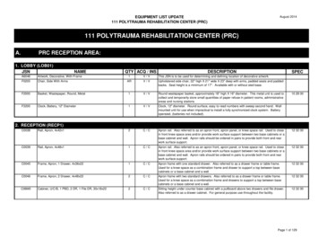
Mini-drafter11
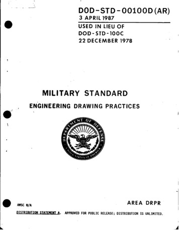
Mini-drafter fixed on a drawing table12
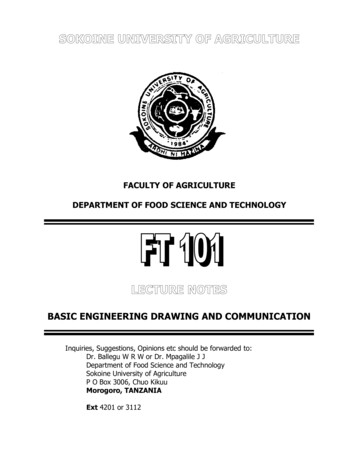
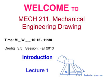
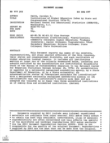
Set-squareDrawing ClipsFrench Curves13
Scale set14
Engineering Drawing Box15
16
Pencils17
Dimensions of Engineer’s Drawing BoardsDesignationLength x Width(mm)Recommended foruse with sheetsizesD01500 x 1000A0D11000 x 700A1D2700 x 500A2D3500 x 500A3D0 and D1 for drawing offices, for students use – D218
Standard sizes of drawing sheets as per BISDesignationA0Size(mm)841 x 1189A1594 x 841A2420 x 594A3297 x 420A4210 x 29719
DrawingSheetSizes20
Drawing sheet Layout21
Title Block22
LINES AND LETTERING*LINESLines are the basic feature of a drawing. A line maybe straight, curved, continuous, segmented, thin,thick, etc., each having its own specific sense.Line strokes refer to the directions of drawingstraight and curved lines*standard given in BIS : SP-46, 2003Available in //intranet.iitg.ernet.in/bis asp/start.shtml8/11/201123
Line StrokesVertical and inclined lines are drawn from top to bottom,horizontal lines are drawn from left to right. Curved linesare drawn from left to right or top to bottom.8/11/201124
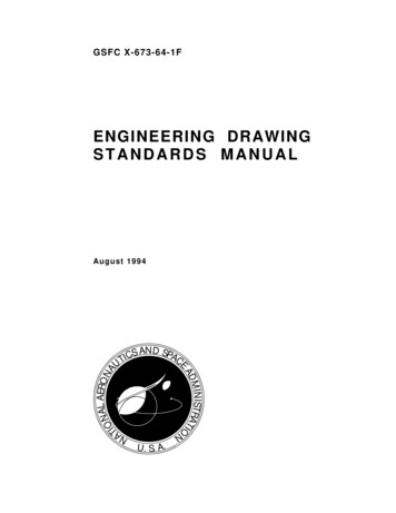
Line typesIllustrationApplicationThickOutlines, visible edges, surfaceboundaries of objects, margin linesContinuous thinDimension lines, extension lines,section lines leader or pointer lines,construction lines, boarder linesContinuous thin wavyContinuous thin with zig-zagShort dashes, gap 1, length 3 mm8/11/2011Short break lines or irregularboundary lines – drawn freehandLong break linesInvisible or interior surfaces25
Line typesIllustrationApplicationShort dashesCenter lines, locus linesAlternatelong and shortdashes in a proportion of 6:1,Long chain thick at end andthin elsewhereContinuous thick border line8/11/2011Cutting plane linesBorder26
Uses of different types of lines in a given drawing8/11/201127
Units of MeasurementInternational systems of units (SI) – which is basedon the meter.Millimeter (mm) - The common SI unit of measure onengineering drawing.Individual identification of linear units is notrequired if all dimensions on a drawing are in thesame unit (mm).The drawing shall however contain a note: ALLDIMENSIONS ARE IN MM. (Bottom left corneroutside the title box)8/11/201128
DimensioningIndicating on a drawing, the size of the object andother details essential for its construction andfunction, using lines, numerals, symbols, notes, etc.Dimensions indicated on a drawing should be thosethat are essential for the production, inspection andfunctioning of the object.Dimensions indicated should not be mistaken asthose that are required to make the drawing of anobject.8/11/2011
An example30
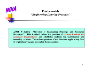
Extension line – a thin, solid lineperpendicular to a dimension line,indicating which feature is associated withthe dimension.Visible gap – there should be a visiblegap of 1.5 mm between the feature’scorners and the end of the extension line.8/11/201131
Leader lineA thin, solid line used to indicate the feature withwhich a dimension, note, or symbol isassociated.Generally a straight line drawn at an angle that isneither horizontal nor vertical.Terminated with an arrow touching the part ordetail.On the end opposite the arrow, the leader line willhave a short, horizontal shoulder. Text isextended from this shoulder such that the textheight is centered with the shoulder line.8/11/201132
Arrows3 mm wide and should be 1/3rd as wide as they arelong - symbols placed at the end of dimension lines toshow the limits of the dimension. Arrows are uniformin size and style, regardless of the size of the drawing.8/11/201133
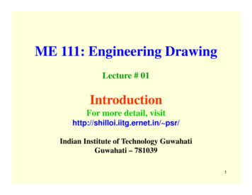
Spacing of Dimensions34
Placing of DimensionsOrientation of Dimensioning Text35
Dimensioning of angles8/11/201136
Dimensioning of Circular FeaturesA circle should be dimensioned by giving its diameterinsteadofradius.Thedimension indicating adiameter should always be preceded by the symbol ø,8/11/201137
Dimensioning a LengthDepends on Available Space38
Dimensioning RadiiArcs of Circle Precede with ‘R’ to distinguish from length39
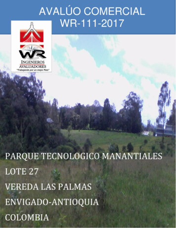
RULES OF DIMENSIONING1. Between any two extension lines, there must be one and only onedimension line bearing one dimension.2. As far as possible, all the dimensions should be placed outside theviews. Inside dimensions are preferred only if they are clearer andmore easily readable.3. All the dimensions on a drawing must be shown using either AlignedSystem or Unidirectional System. In no case should, the two systemsbe mixed on the same drawing.4. The same unit of length should be used for all the dimensions on adrawing. The unit should not be written after each dimension, but anote mentioning the unit should be placed below the drawing.5. Dimension lines should not cross each other. Dimension lines shouldalso not cross any other lines of the object.6. All dimensions must be given.7. Each dimension should be given only once. No dimension should beredundant.8/11/2011
8. Do not use an outline or a centre line as a dimension line. A centre linemay be extended to serve as an extension line.9. Avoid dimensioning hidden lines.10. For dimensions in series, adopt any one of the following ways.i.Chain dimensioning (Continuous dimensioning) All thedimensions are aligned in such a way that an arrowhead of onedimension touches tip-to-tip the arrowhead of the adjacentdimension. The overall dimension is placed outside the othersmaller dimensions.ii. Parallel dimensioning (Progressive dimensioning) All thedimensions are shown from a common reference line. Obviously,all these dimensions share a common extension line. This methodis adopted when dimensions have to be established from aparticular datum surfaceiii. Combined dimensioning When both the methods, i.e., chaindimensioning and parallel dimensioning are used on the samedrawing, the method of dimensioning is called combineddimensioning.8/11/2011
Dimensioning GuidelinesAvoid crossing extension linesMultiple extensionline crossings maybeconfusedforthe outside cornerof the part.42
Single stroke refers to the thickness obtained in one stroke of a pencilor ink pen . It does not mean that the pencil or pen should not be lifted whilecompleting a particular letter.Lettering types Lettering A – Height of the capital letter is divided into 14 equal parts Lettering B – Height of the capital letter is divided into 10 equal parts8/11/201143
Specifications of A -Type LetteringSpecificationsCapital letter heightValueSize (mm)h2.53.557101420a (5/7)h-2.53.5571014Thickness of linesb (1/14)h0.180.250.350.50.711.4Spacing betweencharactersc (1/7)h0.350.50.711.422.8Min. spacing b/n wordsd (3/7)h1.051.52.134.268.4e (10/7)h3.55710142028Lowercase letter heightMin. spacing b/n baselinesRatio of height to width varies, but in most cases is 6:5
8/11/201145
long - symbols placed at the end of dimension lines to show the limits of the dimension. Arrows are uniform in size and style, regardless of the size of the drawing. 8/11/2011 33. Spacing of Dimensions 34. Placing of Dimensions Orientation of Dimensioning Text 35. Dimensioning of angles 8/11/2011 36. Dimensioning of Circular Features A circle should be dimensioned by giving its diameter .