Transcription
Dimensioning andTolerancing
Dimensioning Before an object can be built, completeinformation about both the size and shapeof the object must be available. The exactshape of an object is communicatedthrough orthographic drawings, which aredeveloped following standard drawingpractices. The process of adding sizeinformation to a drawing is known asdimensioning the drawing.
Dimensioning Geometrics is the science of specifyingand tolerancing the shapes and locations offeatures on objects. Once the shape of apart is defined with an orthographicdrawings, the size information is added alsoin the form of dimensions.Dimensioning a drawing also identifies thetolerance (or accuracy) required for eachdimension.
DimensioningIf a part is dimensioned properly, thenthe intent of the designer is clear toboth the person making the part andthe inspector checking the part. A fully defined part has threeelements: graphics, dimensions, andwords (notes).
Size and LocationDimensions A well dimensioned part will communicatethe size and location requirements for eachfeature. Communications is the fundamentalpurpose of dimensions.Parts are dimensioned based on twocriteria: Basic size and locations of the features.Details of a part's construction and formanufacturing.
Unit of measure On a drawing used in American industry, alldimensions are in inches, unless otherwisestated.Most countries outside of the United Statesuse the metric system of measure, or theinternational system of units (SI), which isbased on the meter.The SI system is being used more in theUnited States because of global trade andmultinational company affiliations
Unit of measureOccasionally, a company will useddual dimensioning, that is, both metricand English measurements on adrawing. Angular dimensions are shown eitherin decimal degrees or in degrees,minutes, and seconds.
Terminology Dimension is the numerical value thatdefines the size or geometric characteristicof a feature.Basic dimension is the numerical valuedefining the theoretically exact size of afeature.Reference dimension is the numericalvalue enclosed in parentheses provided forinformation only and is not used in thefabrication of the part.
Terminology Dimension line is the thin solid line whichshows the extent and direction of adimension.Arrows are placed at the ends of dimensionlines to show the limits of the dimension.Extension line is the thin solid lineperpendicular to a dimension line indicatingwhich feature is associated with thedimension.
Terminology Leader line is the thin solid line used toindicate the feature with which a dimension,note, or symbol is associated.Tolerance is the amount a particulardimension is allowed to vary.Plus and minus dimensioning is theallowable positive and negative variancefrom the dimension specified.
Terminology Limits of size is the largestacceptable size and the minimumacceptable size of a feature.The largest acceptable size isexpressed as the maximum materialcondition (MMC) The smallest acceptable size isexpressed as the least materialcondition (LMC).
Terminology Diameter symbol is the symbol which isplaced preceding a numerical valueindicating that the associated dimensionshows the diameter of a circle. The symbolused is the Greek letter phi.Radius symbol is the symbol which isplaced preceding a numerical valueindicating that the associated dimensionshows the radius of a circle. The radiussymbol used is the capital letter R.
Terminology Datum is the theoretically exact pointused as a reference for tabulardimensioning.
Basic Concepts Dimensions are used to describe thesize and location of features on partsfor manufacture. The basic criterion is,"What information is necessary tomake the object?" Dimensions shouldnot be excessive, either throughduplication or dimensioning a featuremore than one way.
Basic Concepts Size dimensionmight be the overallwidth of the part orthe diameter of adrilled hole.Location dimensionmight be lengthfrom the edge ofthe object to thecenter of the drilledhole.
Basic Concepts Size dimensions HorizontalVerticalDiameterRadiusLocation andOrientation HorizontalVerticalAngle
Basic Concepts Rectangular coordinate dimensioning, abase line (or datum line) is established foreach coordinate direction, and alldimensions specified with respect to thesebaselines. This is also known as datumdimensioning, or baseline dimensioning.All dimensions are calculated as X and Ydistances from an origin point, usuallyplaced at the lower left corner of the part.
Standard PracticesPlacement Dimensionplacement dependson the spaceavailable betweenextension lines.When spacepermits,dimensions andarrows are placedbetween theextension lines.
Standard Practices- Spacing The minimum distancefrom the object to the firstdimension is 10mm (3/8inch). The minimumspacing betweendimensions is 6mm (1/4inch).There should be a visiblegap between anextension line and thefeature to which it refers.Extension lines shouldextend about 1mm (1/32inch) beyond the lastdimension line.
Standard PracticesGrouping Dimensions should be grouped for uniformappearance as shown.
Standard PracticesStaggering Where there areseveral paralleldimensions, thevalues should bestaggered.
Standard PracticesExtension lines Extension lines areused to refer adimension to aparticular feature andare usually drawnperpendicular to theassociated dimensionline. Where space islimited, extension linesmay be drawn at anangle.
Standard PracticesExtension lines Extension lines shouldnot cross dimensionlines, and should avoidcrossing other extensionlines whenever possible.When extension linescross object lines or otherextension lines, they arenot broken.When extension linescross or are close toarrowheads, they arebroken for thearrowhead.
Standard PracticesExtension lines When the location ofthe center of a featureis being dimensioned,the center line of thefeature is used as anextension line.When a point is beinglocated by extensionlines only, theextensions lines mustpass through the point.
Standard Practices- Limitedlength or areas When it is necessary to define a limited lengthor area that is to receive additional treatment(such as the knurled portion of a shaft), theextent of the limits may be shown by a chainline. The chain line is drawn parallel to thesurface being defined.
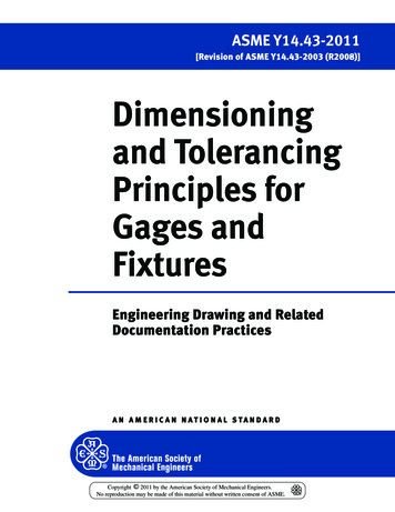
Standard Practices- ReadingDirection All dimension and note text must be oriented to be readfrom the bottom of the drawing (relative to the drawingformat).Placement of all text to be read from the bottom of thedrawing is called unidirectional dimensioning.Aligned dimensions have text placed parallel to thedimension line with vertical dimensions read from theright of the drawing sheet.
Standard Practices- ViewDimensioning Dimensions are to be kept outside of theboundaries of views of objects whereverpractical.Dimensions may be place within the boundariesof objects in cases where extension or leaderlines would be too long, or where clarity wouldbe improved.
Standard Practices- Out-ofScale Dimensions If it is necessary to include adimension which is out of scale, theout of scale dimension text must beunderlined.
Standard PracticesRepetitive Features The symbol X isused to indicatethe number oftimes a feature isto be repeated.The number ofrepetitions,followed by thesymbol X and aspace precedesthe dimensiontext.
Detail Dimensions Holes Diameters must bedimensioned with thediameter symbolpreceding thenumerical value.When holes aredimensioned with aleader line, the linemust be radial. Aradial line is one thatpasses through thecenter of a circle orarc if extended.
Chamfers Slotted holes
Keyseat andKeyway
Summary
Concentriccircles
Arcs
Screw Threads
Grooves
Manufacturers’gage
DimensionTechniques ContourDimensioning contours or shapes ofthe object aredimensioned in theirmost descriptive view.For example, theradius of a arc wouldbe dimensionedwhere it appears asan arc and not as ahidden feature.
DimensionTechniques GeometricBreakdown a part is to breakthe part into itsgeometricconfigurations.
Dimension Process
Dimension Guidelines The primary guideline is that of clarityand whenever two guidelines appear toconflict, the method which most clearlycommunicates the size information shallprevail. Every dimension must have an associatedtolerance, and that tolerance must be clearlyshown on the drawing.Avoid over-dimensioning a part. Doubledimensioning of a feature is not permitted.Dimensions should be placed in the viewwhich most clearly describes the featurebeing dimensioned.
Dimension Guidelines A minimum spacing between the object anddimensions and between dimensions mustbe maintained.A visible gap shall be placed between theend of extension lines and the feature towhich they refer.Manufacturing methods should not bespecified as part of the dimension unless noother method of manufacturing isacceptable.Placing dimensions within the boundaries ofa view should be avoided wheneverpracticable.
Dimension Guidelines Dimensions for materials typicallymanufactured to gages or code numbersshall be specified by numerical values.Unless otherwise specified, angles shown ondrawings are assumed to be 90 degrees.Dimensioning to hidden lines should beavoided whenever possible. Hidden lines areless clear than visible lines.The depth of blind, counterbored, orcountersunk holes may be specified in anote along with the diameter.
Dimension Guidelines Diameters, radii, squares, counterbores,spotfaces, countersinks, and depth shouldbe specified with the appropriate symbolpreceding the numerical value.Leader lines for diameters and radii shouldbe radial lines.
Tolerancing Tolerance is the total amount a dimensionmay vary and is the difference between theupper (maximum) and lower (minimum)limits.Tolerances are used to control the amountof variation inherent in all manufacturedparts. In particular, tolerances are assignedto mating parts in an assembly.
TolerancingOne of the great advantages of usingtolerances is that it allows forinterchangeable parts, thuspermitting the replacement ofindividual parts. Tolerances are used in productiondrawings to control the manufacturingprocess more accurately and controlthe variation between parts.
Tolerancing Tolerancerepresentation Direct limits or astolerance valuesapplied directly toa dimension.GeometrictolerancesNotes referring tospecific condition.
Tolerancing Tolerancerepresentation Plus/Minus
Tolerancing Important termsNominal size a dimension used todescribe the general size usuallyexpressed in common fractions. Basic size the theoretical size usedas a starting point for the applicationof tolerances. Actual size the measured size of thefinished part after machining.
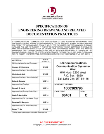
Tolerancing Important terms Limits the maximum and minimum sizesshown by the toleranced dimension.Allowance is the minimum clearance ormaximum interference between parts.Tolerance is the total variance in adimension which is the difference betweenthe upper and lower limits. The tolerance ofthe slot in Figure 14.50 is .004" and thetolerance of the mating part is .002".
Tolerancing Important terms Maximum material condition (MMC)is the condition of a part when itcontains the most amount of material.The MMC of an external feature suchas a shaft is the upper limit. The MMCof an internal feature such as a hole isthe lower limit.
Tolerancing Important terms Least material condition (LMC) isthe condition of a part when it containsthe least amount of material possible.The LMC of an external feature is thelower limit of the part. The LMC of aninternal feature is the upper limit of thepart.
Tolerancing
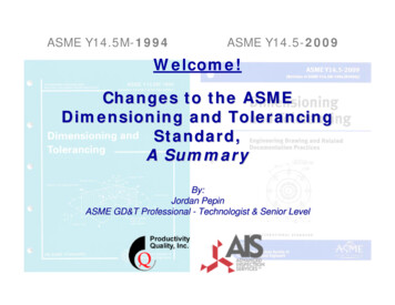
Tolerancing Fit types Clearance fit occurs when two tolerancedmating parts will always leave a space orclearance when assembled.Interference fit occurs when two tolerancedmating parts will always interfere whenassembled.Transition fit occurs when two tolerancedmating parts will sometimes be aninterference fit and sometimes be aclearance fit when assembled.
Tolerancing
Tolerancing
Tolerancing Metric Limits andFits Basic sizeDeviationUpper DeviationLower DeviationFundamentalDeviation
Tolerancing ToleranceTolerance zoneInternationaltolerance gradeHole basisShaft basis
Tolerancing Symbols andDefinitionsMethods
Tolerancing Standard Hole basis table; limits
Tolerancing Hole basis system; fits
Tolerancing Shaft basis system; fits
Tolerancing Standard Precision Fit; English Units Running and Sliding (RC)Clearance Locational (LC)Transition Locational (LT)Interference Locational (LN)Force and Shrinks (FN)
Geometric Dimensioningand Tolerancing GDTis a method of definingparts based on how theyfunction, using standardASME/ANSI symbols.
Geometric Dimensioningand Tolerancing Within the last 15 years there has beenconsiderable interest in GDT, in partbecause of the increased popularity ofstatistical process control. This controlprocess, when combined with GDT, helpsreduce or eliminate inspection of featureson the manufactured object. The flipside isthat the part must be toleranced veryefficiently; this is where GDT comes in.
Geometric Dimensioningand Tolerancing Another reason for the increasedpopularity of GDT is the rise ofworldwide standards, such as ISO9000, which require universallyunderstood and accepted methods ofdocumentation.
GDT-Symbols
GDT Feature control frames
GDT MMC/LMCDatumsGeometric Controls FormOrientationPosition
GDT Forms Straightness Line element Axis
GDT Forms Circularity
GDT Forms Flatness
GDT Forms Cylindricity
GDT Orientation Parallelism
GDT Orientation Perpendicularity
GDT Orientation Angularity
GDT Orientation Line profile
GDT Orientation Surface profile
GDT Location Concentricity
GDT Location Runout
GDT Location Position
GDT Location Position
GDT Tolerance Calculation Floating fastener tolerancing is used toconfirm that loose bolts, screws or otherfasteners have the standard clearance intheir holes.Fixed fastener tolerancing is measured thesame as with floating fasteners except thatthe fastener is already fixed/located on oneof the mating parts and the tolerance is nowdivided between the parts.
GDT Tolerance Calculation Hole diameter tolerancing is used tocalculate the MMC of the hole.
GDT Design Application Five-Step Isolate and define the functions of thefeatures/part. Prioritize the functions. Identify the datum reference frame basedon functional priorities. Select the proper control(s). Calculate the tolerance values.
Standard Practices- Reading Direction All dimension and note text must be oriented to be read from the bottom of the drawing (relative to the drawing format). Placement of all text to be read from the bottom of the drawing is called unidirectional dimensioning. Aligned dimensions have text placed parallel to