Transcription
SPECIFICATION OFENGINEERING DRAWING AND RELATEDDOCUMENTATION PRACTICESL-3 COMMUNICATIONS / COMMUNICATION SYSTEMS-WEST (L-3 CSW) RESTRICTED INFORMATION: THISDOCUMENT CONTAINS RESTRICTED INFORMATION OF L-3 CSW. RECIPIENT AGREES, IN CONSIDERATIONFOR RECEIPT OF THIS DOCUMENT, TO USE IT SOLELY FOR THE LIMITED PURPOSE FOR WHICH IT IS MADEAVAILABLE AND NOT TO TRANSMIT IT AND/OR THE INFORMATION THEREIN CONTAINED, IN WHOLE ORPART, OR TO SUFFER SUCH ACTION BY OTHERS, FOR ANY PURPOSE, EXCEPT WITH THE WRITTENPERMISSION, FIRST OBTAINED, FROM L-3 CSW. THE RECIPIENT FURTHER AGREES TO SURRENDER THEDOCUMENT AND ALL COPIES, OR CERTIFY DESTRUCTION OF THE SAME, TO L-3 CSW WHEN THE REASONFOR ITS RECEIPT HAS TERMINATED. FURTHER DISSEMINATION ONLY AS DIRECTED BY L-3 CSW (06401).DATEAPPROVAL *MO/DAY/YRWritten by (Mechanical Engineer)Gordon W. Cumming6/5/14Approved by (Mgr. Mech.Design)6/9/14Christian L. LottApproved by (Mgr. Manufacturing)Brian L. GrovesL-3 CommunicationsCommunication SystemsWest640 North 2200 WestP.O. Box 16850Salt Lake City, UT 841166/10/14Approved by (Quality)DOCUMENT NUMBER:Russell D. Lund6/16/14Approved by (Supply Chain Eng.)Craig S. Archuleta1000383796CAGE CODE:6/10/1406401Approved by (Dir. Hardware Eng.)Douglas R. Mangum6/12/14Approved by (Dir. Manufacturing)Roger T. Su6/9/14* Official approvals are contained in TeamcenterL-3 CSW PROPRIETARY Copyright L-3 Communications Corporation 2014REV.:C
Pageii of iiiL-3 CSW Engineering Drawing and RelatedDocumentation PracticesDocument Number: 10003837964/11/2016This page intentionally left blankL-3 CSW PROPRIETARY Copyright L-3 Communications Corporation 2014Use or disclosure of the data on this page is subject to the restrictions indicated on the title page.Revision: C
Pageiii of iiiL-3 CSW Engineering Drawing and RelatedDocumentation PracticesDocument Number: 10003837964/11/2016Revision: CTable of Contents1.Purpose . 12.Scope . 13.References . 13.1.4.Cited Standards .1Definitions . 14.1.Derivative Data Set .14.2.Master Data Set .24.3.Product Definition Data Set .25.General Rules . 26.Datum Reference Frame (DRF) . 37.Explicit Feature Definition . 47.1.Feature Tolerance Order of Precedence .48.Implicit Feature Definition . 49.Connector Holes . 610.Inseparable Assembly . 611.Surface Finish . 712.Part Marking . 713.Model Data Standards . 714.Tolerance Tables . 8Table 1: Metal Fabrication Processes, Machined Parts .8Table 2: Metal Fabrication Processes, Formed Sheet Metal Parts .915.Signatures . 1016.Nonmandatory Appendix . 1016.1.17.Examples of Explicit Tolerance Precedence .10Revision History Summary: . 13Copyright . 13L-3 CSW PROPRIETARY Copyright L-3 Communications Corporation 2014Use or disclosure of the data on this page is subject to the restrictions indicated on the title page.
PageL-3 CSW Engineering Drawing and RelatedDocumentation Practices1 of 13Document Number: 10003837964/11/2016Revision: C1. PurposeThe purpose of this document is to define and communicate L-3 CSW engineering drawingand related documentation practices. These practices are based on accepted ASME andother standards. Should there be any conflict between the text of this document and othercited standards, the text of this document shall take precedence. Included items define L-3CSW practices where cited standards provide discretion, lack clarity or L-3 CSW has acompelling need to deviate. This Standard also establishes some default tolerances thatare applicable where explicit tolerances are not given.2. ScopeThis Standard establishes uniform practices used at L-3 CSW for stating and interpretingproduct definition data for use on drawings, master data sets and in related documents. It isapplicable to all CSW hardware parts when referenced in detail or assembly drawing notes,3D CAD models or relevant purchase orders. COTS items, MIL-SPEC items, ElectricalDiagrams (Schematic/Circuit), or Printed Wiring Board and Circuit Card Assembly drawingsare typically excluded. Control drawings, typically Procurement Control or Source ControlDrawings, may also reference this Standard.3. ReferencesThe following documents form a part of this Standard to the extent specified herein. A morerecent revision may be used provided there is no conflict with the text of this Standard. Inthe event of a conflict between the text of this Standard and the references cited herein, thetext of this Standard shall take precedence.3.1. Cited Standards IS-006, Drawing Standards (L-3 CSW Internal Specification for drawing referencedstandards)ASME B46.1-2009, Surface Texture (Surface Roughness, Waviness, and Lay)ASME Y14.41-2012, Digital Product Definition Data PracticesASME Y14.43-2011, Dimensioning and Tolerancing Principles for Gages andFixturesASME Y14.5-2009, Dimensioning and TolerancingASME Y14.5.1M-1994 (R2012), Mathematical Definition of Dimensioning andTolerancing PrinciplesAWS D17.1-2010, Specification for Fusion Welding for Aerospace ApplicationsIEEE/ASTM SI 10-2010, American National Standard for Metric Practice4. Definitions4.1. Derivative Data Setderivative data set: The media created any time data is extracted from a master data setfor machine programming, visual aids, inspection aides, First Article Inspection (FAIs),tool fabrication/measurement, or the like. Derivative data is taken from its nativeenvironment and used in another CAD/CAM, CMM, or manufacturing/inspection system.Derivative data set geometry is modified from the master data set and translated fromL-3 CSW PROPRIETARY Copyright L-3 Communications Corporation 2014Use or disclosure of the data on this page is subject to the restrictions indicated on the title page.
Page2 of 13L-3 CSW Engineering Drawing and RelatedDocumentation PracticesDocument Number: 10003837964/11/2016Revision: Cone system to another using a neutral format translator or manually into some 2Dsystems.4.2. Master Data Setmaster data set: This is the engineering definition typically provided in a 3Drepresentation of the product and viewable on a Computer Aided Design (CAD) system.Models created from the CAD system and provided by L-3 CSW in any of the formatslisted in Model Data Standards are considered part of the master data set.4.3. Product Definition Data Setproduct definition data set: a collection of one or more data file(s) that discloses, directlyor by reference, by means of graphic or textual presentations, or combinations of both,the physical or functional requirements of an item. Figure 4-1 of ASME Y14.41-2012gives a good visual representation of a Product Definition Data Set.5. General RulesWhen interpreting L-3 CSW drawings, CAD models and corresponding data sets, thefollowing rules shall apply.5.1. Unless otherwise specified neither the drawing nor the CAD model represent acomplete product definition by themselves. When both primary documents arerequired for complete product definition, the requirements of ASME Y14.41-2012paragraph 5.2.2 will apply. Either the drawing or the model may refer to otherauxiliary documents. The drawing, 3D CAD model and referenced auxiliarydocuments comprise a product definition data set that provides full product definition.5.1.1. A note similar to the following should be used on all drawings to represent thisrelationship:THIS DRAWING SHALL BE USED WITH MODEL DATA AVAILABLE UNDERTHIS SAME PART NUMBER FOR COMPLETE PRODUCT DEFINITION.5.2. Parts are modeled at their mean condition unless otherwise specified. The meancondition represents the ideal form desired for the part. If a part is modeled atanother condition such as minimum or maximum, a data set note shall state whichcondition the geometry is modeled at.5.2.1. Features are fully modeled to show their net shape mean condition except forthreaded features which are shown symbolically with a 2D LMC surface for thethreads and a 3D MMC surface for the pilot hole. Any other featuresrepresented as something other than their net shape shall be noted in the dataset.5.3. If there is any contradictory information between the master data set and anyexisting drawing, the drawing information shall take precedence.5.4. Feature of Size definition shall be per ASME Y14.5-2009.5.5. Product dimensions apply prior to finish unless otherwise specified.5.6. General default tolerances5.6.1. Internal square cornersThese tolerances apply to corners shown as square corners in the model unlessotherwise shown or specified in the product definition data set.5.6.1.1. Machined tool end radii nominal size shall be R.010 inch maximum.L-3 CSW PROPRIETARY Copyright L-3 Communications Corporation 2014Use or disclosure of the data on this page is subject to the restrictions indicated on the title page.
Page3 of 13L-3 CSW Engineering Drawing and RelatedDocumentation PracticesDocument Number: 10003837964/11/2016Revision: C5.6.1.2. Lathed tool end radii nominal size shall be R.020 inch maximum.5.6.2. Internal corners of D-shaped and DD-shaped holes shall be a .050 inchmaximum radius where the master data set shows a cylindrical surface with adiscontinuous transition to a flat surface.5.7.Unless otherwise specified, where full thread length cannot be achieved withoutthread relief or where thread relief is represented in the CAD model: Thread reliefshall be 1.5 to 2.5 times the thread pitch.5.8. Press fit features shall allow for a .0002 minimum interference fit unless otherwisespecified.5.9. Blind Holes5.9.1. Blind holes shall not breakout unless allowed by a data set note.5.9.2. Depth5.9.2.1. All blind holes, simple or threaded, that do not have an explicitly defineddepth tolerance on the drawing shall have a minimum depth tolerance equalto the model depicted depth minus .010 inches.5.9.2.2. All simple or threaded blind holes shall have a maximum depthtolerance as follows:Maximum depth can be any depth that leaves a minimum material thicknessof .020 inches before break through unless otherwise specified. Minimummaterial thickness to be measured from the drill point.5.9.3. Drill points may be conical or flat.5.10. All welds shall be Class C per AWS D17.1 unless otherwise specified.5.11. The number of significant digits for an implicit nominal dimension is the same asthe significant digits of the tolerance associated with it. The number of significantdigits for an implicit basic dimension is the same as the number of significantdigits used in the solid model to define the feature.5.12. Rounding of dimensions either queried or resolved from the model shall be inaccordance with IEEE/ASTM SI 10.6. Datum Reference Frame (DRF)6.1. Default Datum Reference FrameAll product definition data sets which contain undimensioned geometric featuresrequire implicit geometric controls for full product definition of their geometry. Allsuch cases shall have a DRF explicitly defined in the data set. This singular DRFbecomes the default DRF for all implicit feature definition.6.1.1. The data set shall define the datum order of precedence for the default DRF,i.e., which datums are to be considered primary, secondary and tertiary asnecessary.6.1.2. The data set shall define the material condition (MMC, RFS or LMC) for alldefault DRF datums that are features of size.L-3 CSW PROPRIETARY Copyright L-3 Communications Corporation 2014Use or disclosure of the data on this page is subject to the restrictions indicated on the title page.
Page4 of 13L-3 CSW Engineering Drawing and RelatedDocumentation PracticesDocument Number: 10003837964/11/2016Revision: C6.1.3. The default DRF should have enough constraining degrees of freedom to fullylocate and orient the product. For reference see ASME Y14.5 sections 4.2 – 4.46.2. All DRFs shall be one of the Datum Systems defined in ASME Y14.5.1M-1994(R2012), Section 4.7.7. Explicit Feature DefinitionThese rules and principles apply to all features given explicit nominal dimensions in thedata set.7.1. Feature Tolerance Order of PrecedenceAll feature tolerances in the data set shall have authority to bound feature attributesaccording to the following order of precedence:1) An explicitly defined tolerance specified in a view, table or note on the model ordrawing.2) Applicable tolerances check marked as “Explicit” in Tables 1 and 2.3) Applicable title block tolerances.8. Implicit Feature DefinitionThese rules and principles apply to all features not given explicit dimensioning or tolerancingin the data set.8.1. For implicit feature definition the variable T is equal to the range of the 2 Place TitleBlock Tolerance given in a product definition data set. For example if a 2 Place TitleBlock Tolerance is specified on the drawing as /- .01 then T .02.8.2. Implicit feature tolerances are expressed in multiples of T. For example 2T equals 2times the range of the 2 PL Title Block Tolerance, or .04 if T .02.8.3. Unless otherwise specified the surface profile controlproducts default DRF, shall apply to all features except as follows:, relative to a8.3.1. A Position control ofshall apply to all cylindrical andcircular features of size relative to the product default DRF.8.3.2. Patterns of cylindrical or circular features of size shall be controlled byrelative to the product default DRF.8.3.3. Sheet metal parts: Unless otherwise specified the surface profile control, relative to a products default DRF, shall apply to all featuresexcept as follows:8.3.3.1. A Position control ofshall apply to allcylindrical and circular features of size relative to the product default DRF.8.3.3.2. Patterns of cylindrical or circular features of size shall be controlled byrelative to the product default DRF.8.4. Features that are specified in Tables 1 and 2 shall be controlled by the associatedtolerance given in their respective tables.8.5. If a default DRF is not specified per paragraph 6.1, supplier will specify.L-3 CSW PROPRIETARY Copyright L-3 Communications Corporation 2014Use or disclosure of the data on this page is subject to the restrictions indicated on the title page.
PageL-3 CSW Engineering Drawing and RelatedDocumentation Practices5 of 13Document Number: 10003837964/11/2016Revision: C8.6. Coaxial FeaturesUnless otherwise specified the following features shall be considered a single, localcoaxial pattern which is controlled by the feature control frame specified in 8.3.1 or8.3.3.1 as described in ASME Y14.5-2009 section 7.4.2. A coaxiality tolerance shallalso be applied as indicated with the second listed feature acting as the datum asexemplified in Figure 7-26 of ASME Y14.5-2009. Boss and included hole, Counterbore and companion hole,Countersink and companion hole (no coaxiality control beyond that provided in8.3.1 and 8.3.3.1 is specified). Countersinks shall be controlled on an RFSbasis.L-3 CSW PROPRIETARY Copyright L-3 Communications Corporation 2014Use or disclosure of the data on this page is subject to the restrictions indicated on the title page.
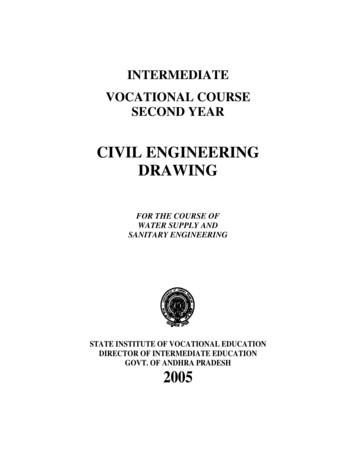
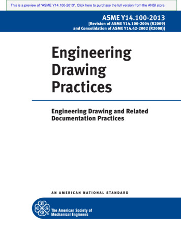
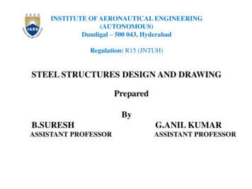
Page6 of 13L-3 CSW Engineering Drawing and RelatedDocumentation PracticesDocument Number: 10003837964/11/2016Revision: C9. Connector HolesWhen it is desired to control the shape and size of D-shaped and DD-shaped connectorholes with an all-around surface profile control as shown in Figure 9-1: An inspection gage or gage set may be used to inspect the hole for compliance to theideal shape and size defined by the all-around profile control. The gage or gage set shall conform to the requirements of ASME Y14.43. The inspection gage or gage set must have the following properties:o The gage(s) shall have an extruded profile shape equal to the profile LMB (ofthe feature to be inspected) .000 / - gage makers tolerance.o The gage(s) shall have an extruded profile shape equal to the profile MMB (ofthe feature to be inspected) gage makers tolerance / - .000.o The length of the extruded profile MMB shape shall be at least three times thedepth of the product feature.o The length of the extruded profile LMB shape shall be equal to or less than thedepth of the product feature.o The inspected feature is acceptable if the following criteria are met: Acceptance Criteria: A visual inspection comparing the LMB gageprofile shall demonstrate that all of the inspected feature boundary lieswithin or is contained within the gage boundary. Acceptance Criteria: The MMB gage profile shall be able to be fullyinserted into the product feature being inspected and not rotate within itmore than 30 degrees in any one direction.Figure 9-1: Example of Profile Control of Connector Holes.10. Inseparable AssemblyUnless otherwise specified the following rules shall apply:10.1.Welded, riveted and bonded assemblies shall be held to the two-place titleblock tolerance for overall size.10.2.Clinch nuts, studs and other inseparable fasteners shall conform torecommended installation tolerances per manufacturer specifications.L-3 CSW PROPRIETARY Copyright L-3 Communications Corporation 2014Use or disclosure of the data on this page is subject to the restrictions indicated on the title page.
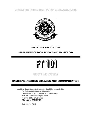
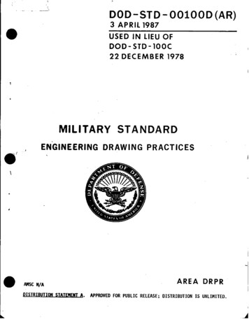
PageL-3 CSW Engineering Drawing and RelatedDocumentation Practices7 of 13Document Number: 10003837964/11/2016Revision: C11. Surface FinishSurface finishes shall conform to ASME B46.1 and shall have the following default valuesunless otherwise specified: Machined parts – 125 µin. Ra or better Lathed parts – 125 µin. Ra or better Sheet metal parts – 250 µin. Ra or better12. Part Marking12.1. Unless otherwise specified parts will be identified by permanent ink, laser markingor by a printed, self adhesive label and located as specified on the drawing.ABA: The area indicated by a phantom line specifies the location of the marking to beon the “NEAR SIDE”.B: The area indicated by a hidden line specifies the location of the marking to be onthe “FAR SIDE”.NOTE: The note “APPROXIMATELY AS SHOWN” on drawings is used to allowsome flexibility in marking location.13. Model Data StandardsL-3 CSW transfers model data in accordance with MIL-STD-1840C and is capable ofreleasing the following file types: Teamcenter/NX documents (*.jt), IGES documents(*.iges,*.igs), STL documents (*.stl), STEP documents (*.step,*.stp), ACIS documents(*.sat), Parasolid documents (*.x b,*.x t), Adobe Acrobat documents (*.pdf) and AutoCADdocuments (*.dwg,*.dxf).L-3 CSW PROPRIETARY Copyright L-3 Communications Corporation 2014Use or disclosure of the data on this page is subject to the restrictions indicated on the title page.
PageDocument Number: 1000383796L-3 CSW Engineering Drawing and RelatedDocumentation Practices8 of 134/11/2016Revision: C14. Tolerance TablesThe following tables define size and form tolerances for certain product features. Thesetolerances are established to best meet the dimensional characteristics of each feature incompliance with form, fit, and function of the designed part assemblies.Table 1: Metal Fabrication Processes, Machined PartsMachined Metal Fabrication Features (in.)Tolerance (in.)Webs and flanges: size2 PL Title Block ToleranceSlots, steps and pockets: width, & depth2 PL Title Block ToleranceD and Double D holes larger than 0 through .250 .003 / - .002D and Double D holes larger than .250 through .500 .005 / - .003D and Double D holes larger than .500 .010 / - .005Width of D (flat to extreme tangent) and Double D(between the two flats) .010 / - .005Holes; 0 through .250 .003 / - .002Holes; larger than .250 through .500 .005 / - .003Holes; larger than .500 .010 / - .005Counterbore Depth /- .010Countersink major ; 0 through .064 material thickness .007 / - .003Countersink major ; larger than .064 material thickness .015 / - .005Outside/overall dimensions2 PL Title Block ToleranceRadii and fillet dimensions2 PL Title Block ToleranceFlatness on planesStraightness, planes, walls flangesRoundness: boss, holes larger than 1.00 inchMill steps tooling mismatch3 PL Title Block ToleranceRange3 PL Title Block ToleranceRange3 PL Title Block ToleranceRange.010 MaximumAxisymmetric FeaturesLathe turning: ID, OD2 PL Title Block ToleranceLength and intersections, depths, steps2 PL Title Block ToleranceRadii and fillet dimensions2 PL Title Block ToleranceMill steps tooling mismatch.010 MaximumL-3 CSW PROPRIETARY Copyright L-3 Communications Corporation 2014Use or disclosure of the data on this page is subject to the restrictions indicated on the title page.ApplicationExplicit Implicit
PageDocument Number: 1000383796L-3 CSW Engineering Drawing and RelatedDocumentation Practices9 of 134/11/2016Revision: CTable 2: Metal Fabrication Processes, Formed Sheet Metal PartsFormed Sheet Metal Fab. FeaturesTolerance (in.)Webs and flanges: size2 PL Title Block ToleranceSlots, steps and pockets: width, & depth2 PL Title Block ToleranceMaterial thickness; 0 through .050 0 through .250Cylindrical, D and Double D holes .003 / - .002Width of D (flat to extreme tangent) and DD(between the two flats) .003 / - .002larger than .250 through .500Cylindrical, D and Double D holes .005 / - .003Width of D (flat to extreme tangent) and DD(between the two flats) .005 / - .003larger than .500Cylindrical, D and Double D holes .010 / - .005Width of D (flat to extreme tangent) and DD(between the two flats) .010 / - .005Material thickness; larger than .050 0 through .250Cylindrical, D and Double D holes .005 / - .002Width of D (flat to extreme tangent) and DD(between the two flats) .005 / - .002larger than .250 through .500Cylindrical, D and Double D holes .007 / - .003Width of D (flat to extreme tangent) and DD(between the two flats) .007 / - .003larger than .500Cylindrical, D and Double D holes .010 / - .005Width of D (flat to extreme tangent) and DD(between the two flats) .010 / - .005Counterbore Depth /- .010Countersink major ; 0 through .064 material thickness .007 / - .003Countersink major ; larger than .064 material thickness .015 / - .005Bending: Bend angle /- 2 L-3 CSW PROPRIETARY Copyright L-3 Communications Corporation 2014Use or disclosure of the data on this page is subject to the restrictions indicated on the title page.ApplicationExplicit Implicit
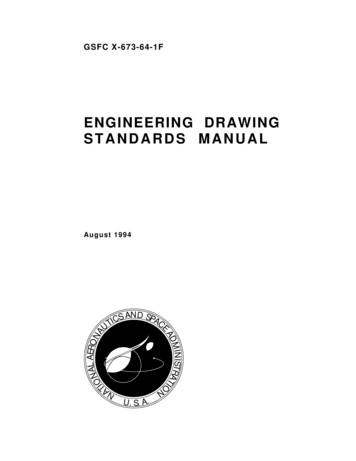
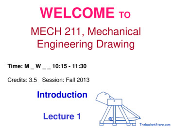
PageL-3 CSW Engineering Drawing and RelatedDocumentation Practices10 of 13Document Number: 10003837964/11/2016Revision: C15. SignaturesThis document is approved and signed by:Director of Hardware EngineeringManager of Mechanical DesignDirector of Manufacturing OperationsManager of Manufacturing Operations: Machining and FabricationDirector of Supply Chain ManagementManager of Inspection/OES16. Nonmandatory Appendix16.1.Examples of Explicit Tolerance PrecedenceThis section provides examples to help one understand the precedence criteriaestablished in section 7.1. The content of this section provides nonmandatoryinformation to clarify points and relationships of the standard for the reader. Text andtolerances in this section are tools to add clarification and do not represent requirements.16.1.1.First Precedence: Explicit ToleranceAn explicit tolerance placed on a drawing or model in a view, table or note has firstprecedence over the tolerance tables in this document or block tolerances. Thistolerance may be given with an explicit nominal dimension as shown in Figure 16-1,in a note or in a table such as Figure 16-2.Figure 16-1: Example of Explicit ToleranceFigure 16-2: Example of Explicit Tolerance Table & Referencing NoteL-3 CSW PROPRIETARY Copyright L-3 Communications Corporation 2014Use or disclosure of the data on this page is subject to the restrictions indicated on the title page.
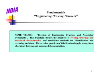
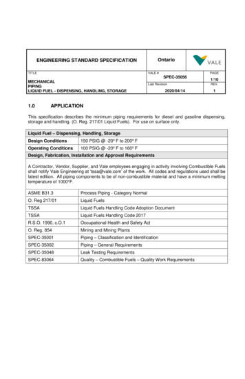
Page11 of 13L-3 CSW Engineering Drawing and RelatedDocumentation PracticesDocument Number: 10003837964/11/2016Revision: C16.1.2.Second Precedence: Tolerance TablesSection 14 table tolerances take secondary precedence for explicit dimensions giventhat the following three criteria are satisfied: An explicit nominal dimension exists on the drawing or model where notolerance is given The feature type is listed in the first column There is a check mark in the Explicit columnFigure 16-3: Example of a Table Tolerance ApplicationFigure 16-3 shows an example where a table tolerance takes precedence over a titleblock tolerance. In this case the explicit nominal dimension O.193 gives the size ofthe cylindrical hole feature but there is no explicit tolerance specified to the right ofthe dimension. The next step is to see if the feature in question is listed in a section14 table. This is a machined hole. Table 1 gives tolerances for machined holes andthe following line is found to apply to this feature.Machined Metal Fabrication Features (in.)Tolerance (in.) Holes; 0 through .250 .003 / - .002ApplicationExplicit ImplicitThe next step is to see if there is a check mark in the Explicit column. In this casethere is a red check mark in that column so the appropriate tolerance for the O.193feature is .003 / - .002.L-3 CSW PROPRIETARY Copyright L-3 Communications Corporation 2014Use or disclosure of the data on this page is subject to the restrictions indicated on the title page.
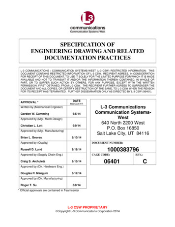
Page12 of 13L-3 CSW Engineering Drawing and RelatedDocumentation PracticesDocument Number: 10003837964/11/2016Revision: C16.1.3.Third Precedence: Title Block TolerancesWhen an explicit dimension is specified on a drawing or model and the criteria forprimary or secondary precedence are not met then title block tolerances control thevariation of the dimension. Two examples are given below in Figure 16-4.Figure 16-4: Examples of Title Block Tolerance ApplicationA portion of a sheet metal part drawing is shown in Figure 16-4. There are twodimensions shown: 2.000 and .08.Let’s consider the 2.000 dimension first. Once it is recognized that an explicitdimension has been defined for a feature the next step is to check the tolerancetables to see if that feature is listed there. The 2.000 dimension can be considered astep feature. Because this is a sheet metal part Table 2 is consulted and thefollowing line is found.Formed Sheet Metal Fab. Features (in.)Tolerance (in.) Slots, steps and pockets: width, & depth2 PL Title Block ToleranceApplicationExplicit ImplicitThere is a line for step features in Table 2 but there is no check mark in the Explicitcolumn. Therefore this dimension does not get its tolerance from Table 2 but iscontrolled by the title block tolerance. This dimension has three digits after thedecimal so it is controlled by the 3 PL title block tolerance which is /- .010 on thisdrawing.Now let’s consider the .08 dimension. Again, it is explicitly defined on the drawing. Ifno dimension were given for a feature then the feature variation would be controlledby the controls listed in section 8. This dimension controls either the location of thehole relative to the edge or it controls the location of the edge relative to the hole. Onanother part of the drawing a position control is found for the pattern of holes so theL-3 CSW PROPRIETARY Copyright L-3 Communications Corporation 2014Use or disclosure of the data on this page is subject to the restrictions indicated on the title page.
Page13 of 13L-3 CSW Engineering Drawing and RelatedDocumentation PracticesDocument Number: 10003837964/11/2016Revision: C.08 must control the location of the edge relative to the hole. Table 2 does not have afeature type description for locating edges therefore the tolerance will come from thetitle block. This dimension has two digits after the decimal so it is controlled by the 2PL title block tolerance which is /- .030 on this drawing.17. Revision History Summary:RevisionABCReason for Update/RevisionInitial release.Standardized title page, header and footer. Addedrevision history summary.Added second sentence to paragraph 5.11.Paragraph 5.9 was expanded into a Blind Holessection to add new blind hole depth defaulttolerances.Date:4/11/
ASME Y14.5-2009, Dimensioning and Tolerancing ASME Y14.5.1M-1994 (R2012), Mathematical Definition of Dimensioning and Tolerancing Principles AWS D17.1-2010, Specification for Fusion Welding for Aerospace Applications IEEE/ASTM SI 10-20