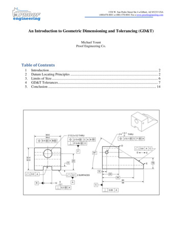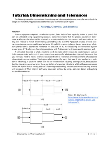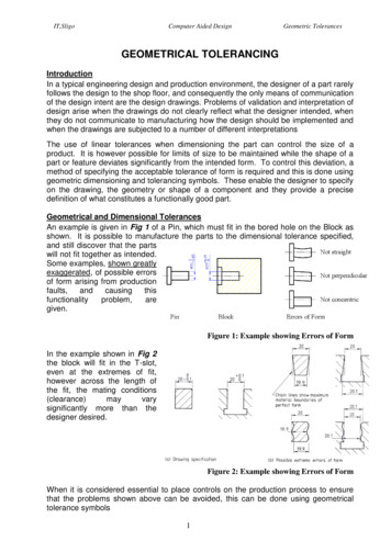
Transcription
ASME Y14.43-2011[Revision of ASME Y14.43-2003 (R2008)]Dimensioningand TolerancingPrinciples forGages andFixturesEngineering Drawing and RelatedDocumentation PracticesA N A M E R I C A N N AT I O N A L STA N DA R DCopyright c 2011 by the American Society of Mechanical Engineers.No reproduction may be made of this material without written consent of ASME.
ASME Y14.43ADOPTION NOTICEASME Y14.43, Dimensioning and Tolerancing Principles for Gages and Fixtures, was adopted on 28 January 2003for use by the Department of Defense (DoD). Proposed changes by DoD activities must be submitted to theDoD Adopting Activity: Commander, U.S. Army Research, Development and Engineering Center (ARDEC),ATTN: RDAR-QES-E, Picatinny Arsenal, NJ 07806-5000. Copies of this document may be purchased from TheAmerican Society of Mechanical Engineers (ASME), 22 Law Drive, P.O. Box 2900, Fairfield, NJ 07007-2900,http://www.asme.org.Custodians:Army — ARNavy — SAAir Force — 16DLA — DHAdopting Activity:Army — AR(Project DRPR-2010-001)Reviewer Activities:Army — CR, MI, PT, TMNavy — AS, CG, CH, EC, MC, NP, TDAir Force — 13, 99DLA — ISOther — MP, NSNOTE: The activities listed above were interested in this document as of the dateof this document. Since organizations and responsibilities can change, you shouldverify the currency of the information above using the ASSIST Online databaseat http://assist.daps.dla.mil.AMSC N/AFSC DRPRDISTRIBUTION STATEMENT A. Approved for public release, distribution is unlimited.Copyright c 2011 by the American Society of Mechanical Engineers.No reproduction may be made of this material without written consent of ASME.
ASME Y14.43-2011[Revision of ASME Y14.43-2003 (R2008)]Dimensioningand TolerancingPrinciples forGages andFixturesEngineering Drawing and RelatedDocumentation PracticesA N A M E R I C A N N AT I O N A L S TA N D A R DThree Park Avenue New York, NY 10016 USACopyright c 2011 by the American Society of Mechanical Engineers.No reproduction may be made of this material without written consent of ASME.
Date of Issuance: August 22, 2011This Standard will be revised when the Society approves the issuance of a new edition.ASME issues written replies to inquiries concerning interpretations of technical aspects of thisStandard. Periodically, certain actions of the ASME Y14 Committee may be published as Code Cases.Cases and interpretations are published on the ASME Web site under the Committee Pages athttp://cstools.asme.org as they are issued.ASME is the registered trademark of The American Society of Mechanical Engineers.This code or standard was developed under procedures accredited as meeting the criteria for American NationalStandards. The Standards Committee that approved the code or standard was balanced to assure that individuals fromcompetent and concerned interests have had an opportunity to participate. The proposed code or standard was madeavailable for public review and comment that provides an opportunity for additional public input from industry, academia,regulatory agencies, and the public-at-large.ASME does not “approve,” “rate,” or “endorse” any item, construction, proprietary device, or activity.ASME does not take any position with respect to the validity of any patent rights asserted in connection with anyitems mentioned in this document, and does not undertake to insure anyone utilizing a standard against liability forinfringement of any applicable letters patent, nor assumes any such liability. Users of a code or standard are expresslyadvised that determination of the validity of any such patent rights, and the risk of infringement of such rights, isentirely their own responsibility.Participation by federal agency representative(s) or person(s) affiliated with industry is not to be interpreted asgovernment or industry endorsement of this code or standard.ASME accepts responsibility for only those interpretations of this document issued in accordance with the establishedASME procedures and policies, which precludes the issuance of interpretations by individuals.No part of this document may be reproduced in any form,in an electronic retrieval system or otherwise,without the prior written permission of the publisher.The American Society of Mechanical EngineersThree Park Avenue, New York, NY 10016-5990Copyright 2011 byTHE AMERICAN SOCIETY OF MECHANICAL ENGINEERSAll rights reservedPrinted in U.S.A.Copyright c 2011 by the American Society of Mechanical Engineers.No reproduction may be made of this material without written consent of ASME.
CONTENTSForeword . . . . . . . . . . . . . . . . . . . . . . . . . . . . . . . . . . . . . . . . . . . . . . . . . . . . . . . . . . . . . . . . . . . . . . . . . . . . . .Committee Roster . . . . . . . . . . . . . . . . . . . . . . . . . . . . . . . . . . . . . . . . . . . . . . . . . . . . . . . . . . . . . . . . . . . . .Correspondence With the Y14 Committee . . . . . . . . . . . . . . . . . . . . . . . . . . . . . . . . . . . . . . . . . . . . . .ivvivii1General. . . . . . . . . . . . . . . . . . . . . . . . . . . . . . . . . . . . . . . . . . . . . . . . . . . . . . . . . . . . . . . . . . . . . . . . . . .12References. . . . . . . . . . . . . . . . . . . . . . . . . . . . . . . . . . . . . . . . . . . . . . . . . . . . . . . . . . . . . . . . . . . . . . . .13Definitions. . . . . . . . . . . . . . . . . . . . . . . . . . . . . . . . . . . . . . . . . . . . . . . . . . . . . . . . . . . . . . . . . . . . . . . .14Principles. . . . . . . . . . . . . . . . . . . . . . . . . . . . . . . . . . . . . . . . . . . . . . . . . . . . . . . . . . . . . . . . . . . . . . . . .45Gage Design . . . . . . . . . . . . . . . . . . . . . . . . . . . . . . . . . . . . . . . . . . . . . . . . . . . . . . . . . . . . . . . . . . . . . .106Dimensioning and Tolerancing . . . . . . . . . . . . . . . . . . . . . . . . . . . . . . . . . . . . . . . . . . . . . . . . . . . . .187Usage . . . . . . . . . . . . . . . . . . . . . . . . . . . . . . . . . . . . . . . . . . . . . . . . . . . . . . . . . . . . . . . . . . . . . . . . . . . .308Fixtures. . . . . . . . . . . . . . . . . . . . . . . . . . . . . . . . . . . . . . . . . . . . . . . . . . . . . . . . . . . . . . . . . . . . . . . . . . .33Figures5-1 Fixed Pin Construction . . . . . . . . . . . . . . . . . . . . . . . . . . . . . . . . . . . . . . . . . . . . . . . . . . . . . . . . . . .5-2 Push Pin Construction — Type 1 . . . . . . . . . . . . . . . . . . . . . . . . . . . . . . . . . . . . . . . . . . . . . . . . .5-3 Push Pin Construction — Type 2 . . . . . . . . . . . . . . . . . . . . . . . . . . . . . . . . . . . . . . . . . . . . . . . . .6-1 Datum Target Symbol . . . . . . . . . . . . . . . . . . . . . . . . . . . . . . . . . . . . . . . . . . . . . . . . . . . . . . . . . . . .6-2 Absolute Tolerancing Method . . . . . . . . . . . . . . . . . . . . . . . . . . . . . . . . . . . . . . . . . . . . . . . . . . . .6-3 Gagemakers’ Tolerance Classes . . . . . . . . . . . . . . . . . . . . . . . . . . . . . . . . . . . . . . . . . . . . . . . . . . .6-4 Gagemakers’ Tolerance Chart . . . . . . . . . . . . . . . . . . . . . . . . . . . . . . . . . . . . . . . . . . . . . . . . . . . .14151620212222Tables6-1 Plug Gage Limit Dimensions — Classes ZM, YM, and XM . . . . . . . . . . . . . . . . . . . . . . . .6-2 Plug Gage Limit Dimensions — Class XXM . . . . . . . . . . . . . . . . . . . . . . . . . . . . . . . . . . . . . . .6-3 Ring and Snap Gage Limit Dimensions — Classes ZM, YM, and XXM . . . . . . . . . . . . .6-4 Ring and Snap Gage Limit Dimensions — Class XXXM . . . . . . . . . . . . . . . . . . . . . . . . . . .23252729Mandatory AppendicesIIllustrations of Gaging Policy . . . . . . . . . . . . . . . . . . . . . . . . . . . . . . . . . . . . . . . . . . . . . . . . . . . . .IIMaterial Condition Explanation . . . . . . . . . . . . . . . . . . . . . . . . . . . . . . . . . . . . . . . . . . . . . . . . . .3541Nonmandatory AppendicesAExamples of Gage Characteristics . . . . . . . . . . . . . . . . . . . . . . . . . . . . . . . . . . . . . . . . . . . . . . . .BGaging Examples and Illustrations . . . . . . . . . . . . . . . . . . . . . . . . . . . . . . . . . . . . . . . . . . . . . . .CRegardless of Feature Size (RFS) and Regardless of Material Boundary (RMB) . . . . .4761129iiiCopyright c 2011 by the American Society of Mechanical Engineers.No reproduction may be made of this material without written consent of ASME.
FOREWORDThis Standard contains information showing methods for creating gages and fixtures for featuresthat use principles found in ASME Y14.5, Dimensioning and Tolerancing. It addresses GO gagesfor measuring maximum material condition (MMC) and NOGO gages for measuring least materialcondition (LMC). This material was developed from ANSI B4.4-1981, Inspection of workpieces,which has since been retired. This Standard addresses functional gages used for the measurementof geometric tolerances, specifically for the verification of virtual condition boundaries [MMCand maximum material boundary (MMB) concepts]. It also shows examples of functional gagesand fixtures used for the measurement of workpiece geometric tolerances referenced at regardlessof feature size (RFS) and regardless of material boundary (RMB). GO, NOGO, and functionalgages are primarily used for the collection of attribute data. Fixtures are used to properly simulatedatum features while an end product is being measured for variable data collection and in certainstages of manufacturing.This Standard shows the principles and choices available to design, dimension, and tolerancegages and fixtures in compliance with the principles in ASME Y14.5-2009 and previous editions.The gages and fixtures displayed in this Standard represent the physical embodiment of thetheory shown in ASME Y14.5 for the simulation of virtual condition (MMC concept) boundariesand proper datum feature simulation.Gages discussed in this Standard deal with the collection of attribute data only (good versusbad information), while fixtures are to be used in conjunction with variable data collection devices.As illustrated in this Standard, fixtures differ from gages in that gages represent referenced datumfeatures and controlled features, while fixtures represent only the referenced datum features.The rules and principles in this Standard are consistent with those in ANSI B4.4 and ASME Y14.5.More information and examples of gages and fixtures are presented in this Standard.The understanding of gages and fixtures is the key to understanding dimensioning and tolerancing of products in accordance with ASME Y14.5.This Standard is intended to serve the needs of those professionals who are designing gagesand fixtures for workpieces dimensioned and toleranced per ASME Y14.5.Following are the revisions to this edition of ASME Y14.43:(a) Tables have been added to show definitions, sizes, tolerances, tolerance distribution, androughness averages for various gage types and classes of fit (ZM, YM, XM, XXM, and XXXM).(b) The datum feature translation symbol is used and its meaning simulated in gages.(c) Moveable datum target simulators are shown for the movable datum target symbol.(d) Oddly configured datum features are simulated in gages with more information on gageelement sizes.(e) More examples of push pin gages are shown.(f) Threaded holes are shown gaged in improved detail.(g) Completely disassemblable gages are shown in greater and improved detail.(h) Curved surfaces as datum features are simulated in gages.(i) Releasing and invoking spatial degrees of freedom for datum features is demonstrated andgaged.(j) Radii referenced as datum features are simulated in gages.(k) Offset slotted datum features are gaged.(l) The new symbol for unequal or unilateral profile tolerances is shown on gages.(m) Planar gaging elements referenced at basic locations are shown.(n) More examples of RFS and RMB datum feature simulators are illustrated.(o) Planar datum features are simulated at RMB and MMB.(p) Datum feature patterns are simulated at RMB with expanding gage pins.(q) More examples of profile of a surface used on oddly configured holes are shown gaged.(r) Conical datum features are shown fixtured in order to gage radial holes.(s) Complex datum patterns referenced at RMB and MMB were added.ivCopyright c 2011 by the American Society of Mechanical Engineers.No reproduction may be made of this material without written consent of ASME.
These revisions are intended to provide the user with more detailed information and a morein-depth understanding of the design, dimensioning, and tolerancing of gages and fixtures thanpreviously presented.Suggestions for improvement of this Standard are welcome. They should be sent to TheAmerican Society of Mechanical Engineers; Attn: Secretary, Y14 Committee; Three Park Avenue;New York, NY 10016.This Standard was approved by ANSI as an American National Standard on January 28, 2011.vCopyright c 2011 by the American Society of Mechanical Engineers.No reproduction may be made of this material without written consent of ASME.
ASME Y14 COMMITTEEEngineering Drawing and Related DocumentationPractices(The following is the roster of the Committee at the time of approval of this Standard.)STANDARDS COMMITTEE OFFICERSF. Bakos, Jr., ChairW. A. Kaba, Vice ChairC. J. Gomez, SecretarySTANDARDS COMMITTEE PERSONNELA. Krulikowski, Effective Training, Inc.E. F. McCarthy, Raytheon Missile SystemsP. J. McCuistion, Ohio UniversityJ. D. Meadows, James D. Meadows & Associates, Inc.M. E. Meloro, Northrop Grumman Corp.H. W. Oakes, U.S. Air ForceN. H. Smith, Spirit AeroSystems, Inc.M. J. Stahl, Caterpillar, Inc.N. Stern, United States ArmyR. G. Wilhelm, University of North CarolinaB. A. Wilson, The Boeing Co.A. R. Anderson, Dimensional Control Systems, Inc.F. Bakos, Jr., ConsultantJ. V. Burleigh, ConsultantD. E. Day, TEC-EASE, Inc.K. Dobert, UGS PLM SolutionsC. J. Gomez, The American Society of Mec
ASME Y14.43, Dimensioning and Tolerancing Principles for Gages and Fixtures, was adopted on 28 January 2003 for use by the Department of Defense (DoD). Proposed changes by DoD activities must be submitted to the DoD Adopting Activity: Commander, U.S. Army Research, Development and Engineering Center (ARDEC), ATTN: RDAR-QES-E, Picatinny Arsenal, NJ 07806-5000. Copies of File Size: 721KBPage Count: 11