Transcription
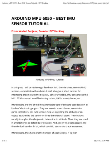
Arduino DC Motor Control Tutorial– L298N PWM H-BridgeIn this Arduino Tutorial we will learn how to control DC motors using Arduino. We well take a lookat some basic techniques for controlling DC motors and make two example through which we willlearn how to control DC motors using the L298N driver and the Arduino board.OverviewWe can control the speed of the DC motor by simply controlling the input voltage to the motorand the most common method of doing that is by using PWM signal.
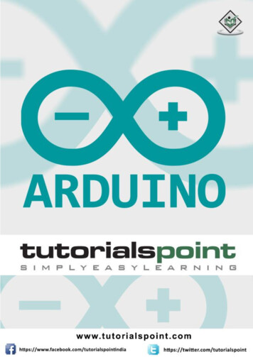
PWM DC Motor ControlPWM, or pulse width modulation is a technique which allows us to adjust the average value of thevoltage that’s going to the electronic device by turning on and off the power at a fast rate. Theaverage voltage depends on the duty cycle, or the amount of time the signal is ON versus theamount of time the signal is OFF in a single period of time.So depending on the size of the motor, we can simply connect an Arduino PWM output to thebase of transistor or the gate of a MOSFET and control the speed of the motor by controlling thePWM output. The low power Arduino PWM signal switches on and off the gate at the MOSFETthrough which the high power motor is driven.
Note: Arduino GND and the motor power supply GND should be connectedtogether.
H-Bridge DC Motor ControlOn the other hand, for controlling the rotation direction, we just need to inverse the direction ofthe current flow through the motor, and the most common method of doing that is by using an HBridge. An H-Bridge circuit contains four switching elements, transistors or MOSFETs, with themotor at the center forming an H-like configuration. By activating two particular switches at thesame time we can change the direction of the current flow, thus change the rotation direction ofthe motor.So if we combine these two methods, the PWM and the H-Bridge, we can have a complete controlover the DC motor. There are many DC motor drivers that have these features and the L298N isone of them.
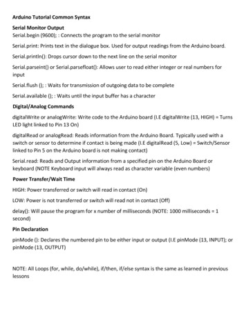
L298N DriverThe L298N is a dual H-Bridge motor driver which allows speed and direction control of two DCmotors at the same time. The module can drive DC motors that have voltages between 5 and35V, with a peak current up to 2A.Let’s take a closer look at the pinout of L298N module and explain how it works. The module hastwo screw terminal blocks for the motor A and B, and another screw terminal block for the Groundpin, the VCC for motor and a 5V pin which can either be an input or output.This depends on the voltage used at the motors VCC. The module have an onboard 5V regulatorwhich is either enabled or disabled using a jumper. If the motor supply voltage is up to 12V wecan enable the 5V regulator and the 5V pin can be used as output, for example for powering ourArduino board. But if the motor voltage is greater than 12V we must disconnect the jumperbecause those voltages will cause damage to the onboard 5V regulator. In this case the 5V pin willbe used as input as we need connect it to a 5V power supply in order the IC to work properly.
We can note here that this IC makes a voltage drop of about 2V. So for example, if we use a 12Vpower supply, the voltage at motors terminals will be about 10V, which means that we won’t beable to get the maximum speed out of our 12V DC motor.Next are the logic control inputs. The Enable A and Enable B pins are used for enabling andcontrolling the speed of the motor. If a jumper is present on this pin, the motor will be enabledand work at maximum speed, and if we remove the jumper we can connect a PWM input to thispin and in that way control the speed of the motor. If we connect this pin to a Ground the motorwill be disabled.Next, the Input 1 and Input 2 pins are used for controlling the rotation direction of the motor A,and the inputs 3 and 4 for the motor B. Using these pins we actually control the switches of theH-Bridge inside the L298N IC. If input 1 is LOW and input 2 is HIGH the motor will move forward,and vice versa, if input 1 is HIGH and input 2 is LOW the motor will move backward. In case both
inputs are same, either LOW or HIGH the motor will stop. The same applies for the inputs 3 and 4and the motor B.Arduino and L298NNow let’s make some practical applications. In the first example we will control the speed of themotor using a potentiometer and change the rotation direction using a push button. Here’s thecircuit schematics.So we need an L298N driver, a DC motor, a potentiometer, a push button and an Arduino board.Arduino CodeHere’s the Arduino code:1. /* Arduino DC Motor Control - PWM H-Bridge L298N - Example 012.3. by Dejan Nedelkovski, www.HowToMechatronics.com4. */5.6. #define enA 97. #define in1 68. #define in2 79. #define button 410.
11. int rotDirection 0;12. int pressed false;13.14. void setup() {15. pinMode(enA, OUTPUT);16. pinMode(in1, OUTPUT);17. pinMode(in2, OUTPUT);18. pinMode(button, INPUT);19. // Set initial rotation direction20. digitalWrite(in1, LOW);21. digitalWrite(in2, HIGH);22. }23.24. void loop() {25. int potValue analogRead(A0); // Read potentiometer value26. int pwmOutput map(potValue, 0, 1023, 0 , 255); // Map the potentiometer valuefrom 0 to 25527. analogWrite(enA, pwmOutput); // Send PWM signal to L298N Enable pin28.29. // Read button - Debounce30. if (digitalRead(button) true) {31. pressed !pressed;32. }33. while (digitalRead(button) true);34. delay(20);35.36. // If button is pressed - change rotation direction37. if (pressed true & rotDirection 0) {38. digitalWrite(in1, HIGH);39. digitalWrite(in2, LOW);40. rotDirection 1;41. delay(20);42. }43. // If button is pressed - change rotation direction44. if (pressed false & rotDirection 1) {45. digitalWrite(in1, LOW);46. digitalWrite(in2, HIGH);47. rotDirection 0;48. delay(20);49. }50. }Description: So first we need to define the pins and some variables needed for the program. Inthe setup section we need to set the pin modes and the initial rotation direction of the motor. Inthe loop section we start by reading the potentiometer value and then map the value that we getfrom it which is from 0 to 1023, to a value from 0 to 255 for the PWM signal, or that’s 0 to 100%
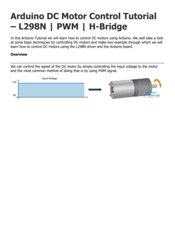
duty cycle of the PWM signal. Then using the analogWrite() function we send the PWM signal tothe Enable pin of the L298N board, which actually drives the motor.Next, we check whether we have pressed the button, and if that’s true, we will change therotation direction of the motor by setting the Input 1 and Input 2 states inversely. The pushbutton will work as toggle button and each time we press it, it will change the rotation direction ofthe motor.Arduino Robot Car Control usingL298N DriverSo once we have learned this, now we can build our own Arduino robot car. Here’s the circuitschematic:All we need is 2 DC Motors, the L298N driver, an Arduino board and a joystick for the control. Asfor the power supply, I chose to use three 3.7V Li-ion batteries, providing total of 11V. I made thechassis out of 3 mm tick plywood, attached the motors to it using metal brackets, attached wheelsto the motors and in front attached a swivel wheel.
Now let’s take a look at the Arduino code and see how it works. (Down below you can find thecomplete code)1. int xAxis analogRead(A0); // Read Joysticks X-axis2. int yAxis analogRead(A1); // Read Joysticks Y-axisAfter defining the pins, in the loop section, we start with reading the joystick X and Y axis values.The joystick is actually made of two potentiometers which are connected to the analog inputs ofthe Arduino and they have values from 0 to 1023. When the joystick stays in its center positionthe value of both potentiometers, or axes is around 512.
We will add a little tolerance and consider the values from 470 to 550 as center. So if we movethe Y axis of joystick backward and the value goes below 470 we will set the two motors rotationdirection to backward using the four input pins. Then, we will convert the declining values from470 to 0 into increasing PWM values from 0 to 255 which is actually the speed of the motor.1. // Y-axis used for forward and backward control2. if (yAxis 470) {3. // Set Motor A backward4. digitalWrite(in1, HIGH);5. digitalWrite(in2, LOW);6. // Set Motor B backward7. digitalWrite(in3, HIGH);8. digitalWrite(in4, LOW);9. // Convert the declining Y-axis readings for going backward from 470 to 0 into 0 to 255value for the PWM signal for increasing the motor speed10. motorSpeedA map(yAxis, 470, 0, 0, 255);11. motorSpeedB map(yAxis, 470, 0, 0, 255);12. }
Similar, if we move the Y axis of the joystick forward and the value goes above 550 we will set themotors to move forward and convert the readings from 550 to 1023 into PWM values from 0 to255. If the joystick stays in its center the motors speed will be zero.Next, let’s see how we use the X axis for the left and right control of the car.1. // X-axis used for left and right control2. if (xAxis 470) {3. // Convert the declining X-axis readings from 470 to 0 into increasing 0 to 255 value4. int xMapped map(xAxis, 470, 0, 0, 255);5. // Move to left - decrease left motor speed, increase right motor speed6. motorSpeedA motorSpeedA - xMapped;7. motorSpeedB motorSpeedB xMapped;8. // Confine the range from 0 to 2559. if (motorSpeedA 0) {10. motorSpeedA 0;11. }12. if (motorSpeedB 255) {13. motorSpeedB 255;14. }15. }So again, first we need to convert the X axis readings into speed values from 0 to 255. For movingleft, we use this value to decrease the left motor speed and increase the right motor speed. Here,because of the arithmetic functions we use two additional “if” statements to confine the range ofthe motor speed from 0 to 255.
The same method is used for moving the car to the right.Depending on the applied voltage and the motor itself, at lower speeds the motor is not able tostart moving and it produces a buzzing sound. In my case, the motors were not able to move ifthe value of the PWM signal was below 70. Therefore using this two if statements I actuallyconfined to speed range from 70 to 255. At the end we just send the final motor speeds or PWMsignal to the enable pins of the L298N driver.1. // Prevent buzzing at low speeds (Adjust according to your motors. My motors couldn'tstart moving if PWM value was below value of 70)2. if (motorSpeedA 70) {3. motorSpeedA 0;4. }5. if (motorSpeedB 70) {6. motorSpeedB 0;7. }8. analogWrite(enA, motorSpeedA); // Send PWM signal to motor A
9. analogWrite(enB, motorSpeedB); // Send PWM signal to motor BHere’s the complete code of the Arduino robot car example:1. /* Arduino DC Motor Control - PWM H-Bridge L298N2. Example 02 - Arduino Robot Car Control3. by Dejan Nedelkovski, www.HowToMechatronics.com4. */5.6. #define enA 97. #define in1 48. #define in2 59. #define enB 1010. #define in3 611. #define in4 712.13. int motorSpeedA 0;14. int motorSpeedB 0;15.16. void setup() {17. pinMode(enA, OUTPUT);18. pinMode(enB, OUTPUT);19. pinMode(in1, OUTPUT);20. pinMode(in2, OUTPUT);21. pinMode(in3, OUTPUT);22. pinMode(in4, OUTPUT);23. }24.25. void loop() {26. int xAxis analogRead(A0); // Read Joysticks X-axis27. int yAxis analogRead(A1); // Read Joysticks Y-axis28.29. // Y-axis used for forward and backward control30. if (yAxis 470) {31. // Set Motor A backward32. digitalWrite(in1, HIGH);33. digitalWrite(in2, LOW);34. // Set Motor B backward35. digitalWrite(in3, HIGH);36. digitalWrite(in4, LOW);37. // Convert the declining Y-axis readings for going backward from 470 to 0 into 0 to255 value for the PWM signal for increasing the motor speed38. motorSpeedA map(yAxis, 470, 0, 0, 255);39. motorSpeedB map(yAxis, 470, 0, 0, 255);40. }41. else if (yAxis 550) {42. // Set Motor A forward
43. digitalWrite(in1, LOW);44. digitalWrite(in2, HIGH);45. // Set Motor B forward46. digitalWrite(in3, LOW);47. digitalWrite(in4, HIGH);48. // Convert the increasing Y-axis readings for going forward from 550 to 1023 into 0 to255 value for the PWM signal for increasing the motor speed49. motorSpeedA map(yAxis, 550, 1023, 0, 255);50. motorSpeedB map(yAxis, 550, 1023, 0, 255);51. }52. // If joystick stays in middle the motors are not moving53. else {54. motorSpeedA 0;55. motorSpeedB 0;56. }57.58. // X-axis used for left and right control59. if (xAxis 470) {60. // Convert the declining X-axis readings from 470 to 0 into increasing 0 to 255 value61. int xMapped map(xAxis, 470, 0, 0, 255);62. // Move to left - decrease left motor speed, increase right motor speed63. motorSpeedA motorSpeedA - xMapped;64. motorSpeedB motorSpeedB xMapped;65. // Confine the range from 0 to 25566. if (motorSpeedA 0) {67. motorSpeedA 0;68. }69. if (motorSpeedB 255) {70. motorSpeedB 255;71. }72. }73. if (xAxis 550) {74. // Convert the increasing X-axis readings from 550 to 1023 into 0 to 255 value75. int xMapped map(xAxis, 550, 1023, 0, 255);76. // Move right - decrease right motor speed, increase left motor speed77. motorSpeedA motorSpeedA xMapped;78. motorSpeedB motorSpeedB - xMapped;79. // Confine the range from 0 to 25580. if (motorSpeedA 255) {81. motorSpeedA 255;82. }83. if (motorSpeedB 0) {84. motorSpeedB 0;85. }86. }
87. // Prevent buzzing at low speeds (Adjust according to your motors. My motors couldn'tstart moving if PWM value was below value of 70)88. if (motorSpeedA 70) {89. motorSpeedA 0;90. }91. if (motorSpeedB 70) {92. motorSpeedB 0;93. }94. analogWrite(enA, motorSpeedA); // Send PWM signal to motor A95. analogWrite(enB, motorSpeedB); // Send PWM signal to motor B96. }So that would be all for this tutorial, and in my next video we will upgrade this Arduino robot car,by adding a Bluetooth and Radio devices for enabling smartphone and wireless control.
Arduino Robot Car Control using L298N Driver So once we have learned this, now we can build our own Arduino robot car. Here’s the circuit schematic: All we need is 2 DC Motors, the L298N driver, an Arduino board and a joystick for the control. As for the power supply, I chose to use three