Transcription
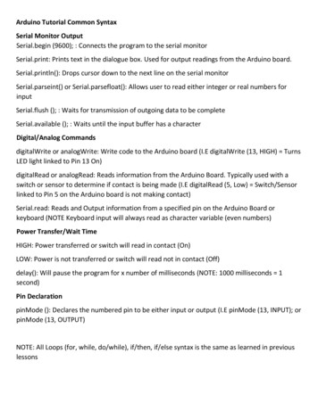
Arduino Tutorial Common SyntaxSerial Monitor OutputSerial.begin (9600); : Connects the program to the serial monitorSerial.print: Prints text in the dialogue box. Used for output readings from the Arduino board.Serial.println(): Drops cursor down to the next line on the serial monitorSerial.parseint() or Serial.parsefloat(): Allows user to read either integer or real numbers forinputSerial.flush (); : Waits for transmission of outgoing data to be completeSerial.available (); : Waits until the input buffer has a characterDigital/Analog CommandsdigitalWrite or analogWrite: Write code to the Arduino board (I.E digitalWrite (13, HIGH) TurnsLED light linked to Pin 13 On)digitalRead or analogRead: Reads information from the Arduino Board. Typically used with aswitch or sensor to determine if contact is being made (I.E digitalRead (5, Low) Switch/Sensorlinked to Pin 5 on the Arduino board is not making contact)Serial.read: Reads and Output information from a specified pin on the Arduino Board orkeyboard (NOTE Keyboard input will always read as character variable (even numbers)Power Transfer/Wait TimeHIGH: Power transferred or switch will read in contact (On)LOW: Power is not transferred or switch will read not in contact (Off)delay(): Will pause the program for x number of milliseconds (NOTE: 1000 milliseconds 1second)Pin DeclarationpinMode (): Declares the numbered pin to be either input or output (I.E pinMode (13, INPUT); orpinMode (13, OUTPUT)NOTE: All Loops (for, while, do/while), if/then, if/else syntax is the same as learned in previouslessons
Basic Anatomy of the Arduino BoardBreadboard Setup
Reading a Resistor
Workspace SetupNOTE: It is not necessary to declare the #include iostream library or to int main() in yourprogram.Those codes are prebuilt into the structure of the Arduino program.NOTE: Change Font Height of Text: Pull Down Menu File Preferences Font Change todesired text heightUpload: Sendscode to ArduinoSoftware provides 2 default functions:void setup(){}: only runs the codebetween braces one timeVerify: Compiles codeand outputs any errorsvoid loop(){}: runs code between thebraces infinitely. There is no way to endit. However program can be designed ina way to trap the program in an infiniteloop that will not execute anycommands within the loopDialogue Box: Verify Program orshow errorsConnecting Arduino Uno to the ComputerNOTE: These steps should been done each time Arduino Software is used.1. Using the USB-Fire Wire connector, connect the Arduino Board to the computer2. Open Arduino Software from the desktop3. Setting up Arudino Board Set the followinga Tools Board Select Arduino Unob Tools Port Select the Com# Port that has (Arduino Uno) in parentheses (NOTE: if Arduino Unodoes not show up; look at the list of ports unplug the wire see which port disappears (rememberthe number) replug the wire in and choose the port that had disappeared from the list in theprevious step)c Tools Programmer USBaspThis will set the communication between the PC and the Arduino
Program 1: Flashing Light and Hello World!Part 1: Turn on a light for a specified durationYellow Wire Ground WireWhite Wire Power Wireconnects intoPort 13 toNegative columnon breadboardNOTE: Connection ports DO NOT need to be the same as long as the wires and electricalcomponents match up properly.NOTE: LED Anode (Long Leg) should always be linked to the resistor and Cathode (short Side)linked to the ground or the direction the circuit is going.Long Leg Electricity In, (Positive)Short Leg Electricity Out, - (Negative)
Program CodeType following codeSave Program as BlinkConnect the Arduino Board to the computer using the USB-Fire Wire Cable.NOTE: If board is not connected through a COM port unplug the board and reconnect with thesteps listed above (Page 4 Connecting Arduino Board to Computer)Result: Light should turn on for 1 second and then turn offPart 2: Make the light blink repeatedly1. Copy the code from the void setup() and paste in the void loop() 2.Add a delay statement after the digitalWrite (13, LOW) of 200.3. This will make the light flash on and off repeatedly. Experiment in changing the delays toalter the flashing of the light.
Part 3: Adding Input/Output , Variables, If/Statement, and Loops 1.Delete the Blink Code; Type the following Code
2. Modify the code to do the followinga. Change the code to calculate the volume of a coneb. Flash the lights as followsi. Volume 100- Flash ON 2 sec- OFF 2sec- 3 Times (USE For Loop or Do/While Loop)ii. 100 Volume 500- Flash ON 1 sec- OFF 3 sec- 3 Times (USE For Loop or Do/While Loop)iii. Volume 500- Flash ON .5 sec- OFF 2sec- 3 Times (USE For Loop or Do/While Loop)Part 4: Limiting the times through the loopNOTE: There is no way to exit the Void Loop() in Arduino. However a delay statement ormoving into a loop that does nothing can solve this problem. (I.E delay (100000000); orCreate a Loop: while (TRUE) {} (while TRUE will always make the loop true so it will runinfinitely.) Modify the program to do the following1. After the first time through the program ask the user of they want to find the volume ofanother cone. Use 0 or Yes and 1 for Noa. If Yes repeat the programb. If No end the program and say “Goodbye!”
Program 2: Switch StatementCircuit DesignNOTE: LED Anode (Long Leg) should always be linked to the resistor and Cathode (short Side)linked to the ground or the direction the circuit is going.Long Leg Electricty In, (Positive)Short Leg Electricity Out, - (Negative)
Program CodeSwitch statement is like an If/Else/If/Else Statement. It only allows the user to compare discretevalues (one thing at a time). It is not possible to compare ranges of objects. (For that an Ifstatement is needed).Program uses the Serial Monitor. Type in the characters a, b, c, d, e will turn on the LEDS theyare connected to.Using a Switch/Case statement isthe equivalent of writing multipleIf/Else StatementsFor Example:Switch (inByte) { case ‘a’: }is equivalent to writingif (inByte ‘a’){then do this line(s) of code}
Upload the program to test it.Notice how when one key is pressed then another the light of the previouskey does not turn off.Assignment: LED Lights Modify the program to do the following1. Only have the inputted LED Lamp Turned ON (All other LED’s turn off with each new input) I.EWhen ‘a’ is pressed ‘a’ LED light is on, then when ‘b’ is pressed the ‘b’ LED light is on and the ‘a’LED is turned off.2. Output if Input is NOT a, b, c, d, or ea. Blink all of the LED Lamps for a duration of 2 secondsb. Output in the Serial Monitor “ERROR, INPUT INVALID!”(HINT: if inbyte 97 inbyte 101)NOTE: Serial.read converts all input to ASCCII code form. See below of values
Wiring Diagram Option 1Program 3: Push ButtonDirect Wiring to ArduinoSource CodeDefines each pinVCC VoltGND GroundGrey Wire: Out goes to Port 13Out Digital Signal PortBrown Wire: GND goes to GNDRed Wire: VCC to 5VWiring Diagram Option 2Direct Wiring to ArduinoBrown Wire: Ground (GND) to ArduinoGround (GND)Align each wire in thesame row as the pinconnectionRed Wire: Voltage (VCC) to Arduino 5VGrey Wire: Out to Arduino Port 13TopShows what each pinrepresentsBackLeft SideFRONT
Assignment: Push Button1. Modify the program so the serial monitor screen showsa. Text On (Button Pressed) and Off (Button Released)b. Counter showing how many times the button has been released2. Limit of On/Offa. Maximum presses 5b. Once Limit is met do the followingi.Stop the light from turning on and off when button ispressedii. Serial Port Print “ALL DONE!”iii. Only print “ALL DONE!” twice on separate lines(Serial.println)
Program 4: Ultrasonic Sensor
Source Code
Upload Program and Test it. NOTE the program will print the distance in the serial portAssignment: Ultrasonic Sensor1. Add a 220 Ohm resistor and LED on the circuit2. Turn the light on when the an object gets with 20cm of ultrasonic sensor and turns offwhen it is out of rangeProgram 5: Photoresistor SensorAllows the user to implement a variable resistor that uses light to determine the resistanceson the circuit based on the intensity of the light. Can also be used to sense the amount tolight intensity around the photoresistor and then can activate other circuits given a definedset of constraints.Wiring DiagramSent to Arduino Port A0 (This is an Analog Port)Ground Wire is not necessary in this case since wejust want to see how much light is present.Voltage Wire is not needed as well since thesurrounding light could supply the power if needed and adjustbased on the intensity of the lightLegs of the photoresistor are the same. Does notmatter which leg the wire lines up to
Write the following programa.b.c.Testing:Upload the programOpen the Serial MonitorPlace your hand over the Photoresistor Notice the value change. Analyze the dataClose the Serial Monitor Click on Tools Drop down menu Select Serial Plotter now thedata is graphed. Analyze the dataAssignment: Simulate Morning, Day and Night Without Looking out the WindowModify the code that can do the following.Wire 3 different color LEDs to Digital Ports 1,2,3 (May consider using a Switch/Case forcomparison)Declare 3 different ranges (I.E 0-100 Night)1. Represents Dawn/Dusk Middle Values2. Represents Day Highest Values (Maximum amount of light)3. Represents Night: Lowest Values (Least amount of light)
Connecting Arduino Uno to the Computer NOTE: These steps should been done each time Arduino Software is used. 1. Using the USB-Fire Wire connector, connect the Arduino Board to the computer 2. Open Arduino Software from the desktop 3. Setting up Arudino Board Set the following a