Transcription
REM 610Motor Protection RelaySetting calculation tool,Instructions for usemenu 1
1MRS 755111Motor Protection RelayIssued:Version:Setting calculation tool, Instructions for use03.09.2003B/05.01.2005REM 610We reserve the right to change data without prior notice.Contents:1. Program implementation .51.1. Program installation .51.2. Packed program .51.3. Starting the program .52. Main menu .62.1. Functions .62.2. Saving data .62.3. Closing the program .73. Calculating the settings .84. Motor data .94.1. Basic data .94.2. Entering the ambient temperature .105. Calculating the relay set values .125.1. Quick setting .125.2. Normal setting .135.2.1. Thermal overload protection .145.2.1.1. Rated current scaling factor .145.2.1.2. Weighting factor .155.2.1.3. Permitted motor stall time .155.2.1.4. Thermal prior alarm level .165.2.1.5. Restart inhibit level .165.2.1.6. Cooling time multiplier .175.2.2. Start-up supervision .175.2.2.1. Start-up current .185.2.2.2. Start-up time .185.2.3. Short circuit protection .185.2.4. Earth-fault protection .195.2.5. Phase unbalance protection .205.2.5.1. Start current .205.2.5.2. Calculating the operate time .205.2.6. Undercurrent protection .225.2.6.1. Start current .225.2.6.2. Operate time .225.2.7. Cumulative start-up time counter .235.2.7.1. Fields .235.2.7.2. Restart inhibit start count setting .235.2.7.3. Register countdown rate .233
REM 610Motor Protection Relay1MRS 755111Setting calculation tool, Instructions for use6. Trip curves . 246.1. Curves . 246.2. Printing . 257. Thermal behaviour . 267.1.7.2.7.3.7.4.Cold motor . 26Hot motor . 26Simulating load variation . 26Thermal behaviour curves . 268. Report . 288.1. Contents . 288.1.1. First page . 288.1.2. Second page . 288.1.3. Third page . 288.1.4. Fourth page . 288.1.5. Fifth page . 288.1.6. Printing . 298.1.7. Saving . 294
1MRS 755111Motor Protection RelayREM 610Setting calculation tool, Instructions for use1.Program implementation1.1.Program installationThe program can be used directly from the CD or installed on the PC hard disk. Toinstall the program, copy the REM 610.xls file to the desired directory on the harddisk. The program does not write in Windows registry, so you can easily uninstallit by moving it to the Trash can.1.2.Packed programIf the program is delivered packed, the installation is easy: double-click the REMprogram icon using the left mouse button to open the installation window. In theinstallation window, select the installation directory and click the Unzip button. Theprogram is unzipped in the selected directory where it can be started.1.3.Starting the programThe program works in Microsoft Excel 97 and Office 2000 environments. It requiresone of these programs to work.To open the program, double-click the program icon using the left mouse button.Alternatively, you can start Excel and select the Open command to start the REMprogram from the installation directory.As the program starts, Excel displays a warning about macros that may containdangerous computer viruses. However, not all the macros are viruses or dangerous.The macros contained in the program are designed to perform calculations. If themacros have not been modified, they are not dangerous.!The program contains several macros. The entire operation of the programis based on these macros, so they must be enabled for the program to run.macrovar 2Fig. 1.3.-1 Macro warning5
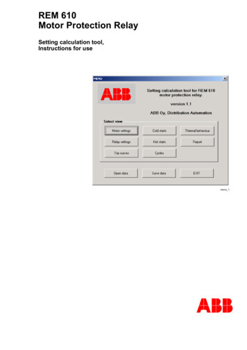
REM 610Motor Protection Relay1MRS 755111Setting calculation tool, Instructions for use2.Main menuThe main menu opens when the program is started. The menu facilitates movingbetween the different parts of the program. To return to the menu from another page,click the MENU button at the bottom of a page.menu 1Fig. 2.-1 Main menu.2.1.FunctionsTo move between the different parts of the program, use the main menu buttons inthe following way:2.2.Motor settingsmotor setting tableRelay settingsrelay setting tableTrip curvestrip curve displayCold startssetting table for cold startsHot startssetting table for hot startsCyclessetting table for varying loadThermal behaviourthermal behaviour plot displayReportreports on calculation resultsSaving dataTo save all the changes for later use, click the Save data button. To retrieve the saveddata, click the Open data button.6
1MRS 755111Motor Protection RelayREM 610Setting calculation tool, Instructions for use2.3.Closing the programWhen the Exit button is clicked, the program warns that closing the program willdelete all unsaved data and asks if you really want to close the program. Click Yesto close the program or No to return to the program.7
REM 610Motor Protection Relay1MRS 755111Setting calculation tool, Instructions for use3.Calculating the settings1. Enter the values for the motor and current transformers (Motor settings).2. Set the ambient temperature (Set ambient temp.).3. Set the scaling factor (Relay settings/p.u. scaling factor).4. Set the weighting factor for the thermal protection (Weighting factor).5. Specify the hot and cold starts (Hot/Cold starts).6. Calculate the motor stall time (Stall time, t6x).7. Check the thermal behaviour (Thermal behaviour).8. Set/calculate the remaining relay settings (Relay settings).9. Check the trip curves (Trip curves).10.Check the report and print it (Report).!8It is recommended you follow the above mentioned sequence to avoidproblems.
1MRS 755111Motor Protection RelayREM 610Setting calculation tool, Instructions for use4.Motor dataTo enter motor data, click the Motor settings button in the main menu to open themotor setting page. To change the motor data, click the Set New Data button. A dialogopens and you can enter the new data. The data is updated on the Motor settings pageimmediately after you click the OK button in the dialog.!4.1.The entered data must be numeric or the program will not accept it.Basic dataThe basic motor data (Insert Data window) can be displayed and modified asdescribed above, see figure 4.1-1. The basic data includes the following:- Namename of the protected motor or object- Rated Power(Pn)- Rated Voltage(Un)- Rated Current(In)- Starting Current(Is)- Starting Time(ts)The rated currents of the primary and secondary windings of the phase currenttransformer and the relay input currents can be set in the Phase CT area.The I0 current transformer data can be entered in the CT for Earth-fault protection area.9
REM 610Motor Protection Relay1MRS 755111Setting calculation tool, Instructions for useinsertdata 5Fig. 4.1.-1 Motor data dialog4.2.Entering the ambient temperatureTo enter the ambient temperature, click the Set ambient temp. button on the MotorSettings, Cold Starts, Hot Starts, Cycles or Trip curves page. Enter the temperature in theopening dialog in degrees Celsius or Fahrenheit. The temperature can be 0 to 70 Cor 32 to 158 F. After confirmation the entered temperature value is displayed on theMotor Settings page.10
1MRS 755111Motor Protection RelayREM 610Setting calculation tool, Instructions for useambtemp 6Fig. 4.2.-1 Ambient temperature dialog11
REM 610Motor Protection Relay1MRS 755111Setting calculation tool, Instructions for use5.Calculating the relay set valuesClick the Relay settings button in the main menu to open the relay setting page. Toreturn to the main menu, click MENU.There are two ways of calculating the relay settings: quick setting or normal setting.See the descriptions of both methods in the following chapters.5.1.Quick settingTo start the quick setting procedure, click the Quick setting button on the relay settingpage. In quick setting, approxinate numbers are calculated prior to calculating theactual values. The method leaves some data uncalculated. When calculating the finalrelay settings, all the settings must be gone through.The quick setting window has the following fields (see figure 5.1-1):- Hot starts: can the motor be started hot once or twice- Short-circuit protection (High-set): is current doubling enabled (Enabled) ordisabled (Disabled)- Start-up supervision: definite time principle (Definite time) thermal stress principle (Thermal stress)- Start-up time counter: 2 or 3 start-ups per hour!12Note the warning in the dialog! The quick setting procedure does notcalculate the earth-fault protection and undercurrent protection settings. Itis recommended that all the relay settings are also calculated after quicksetting according the instructions in the following chapter.
1MRS 755111Motor Protection RelayREM 610Setting calculation tool, Instructions for usequickcalc 7Fig. 5.1.-1 Relay quick setting window.5.2.Normal settingTo view the relay settings, you can click the Relay settings button in the main menu.A window opens showing the current relay settings. To modify the settings, click theRelay settings button to open the relay setting window. Click the buttons in thewindow to calculate the value of the setting and prompt for a confirmation. If youdo not want to use the value suggested by the program you can enter a value usingthe keyboard.13
REM 610Motor Protection Relay1MRS 755111Setting calculation tool, Instructions for userelaysettings 8Fig. 5.2.-1 Relay setting window.5.2.1.Thermal overload protection5.2.1.1.Rated current scaling factorThe settings for the relay thermal overload protection are calculated in the dialogshown in the figure above. The first value calculated is the rated current scalingfactor (p.u. scaling factor), which the program uses in current calculations for a fullmotor load. When you click the button, the program suggests a calculated value. Tochange the value, click No. The program will prompt for a value.p u scalfact 9Fig. 5.2.1.1.-1 To accept the calculated value, click Yes. To change the value, clickNo.14
1MRS 755111Motor Protection RelayREM 610Setting calculation tool, Instructions for useth olunit 10Fig. 5.2.1.1.-2 Entering a value (0.5 to 2.5) for the scaling factor.5.2.1.2.Weighting factorThe weighting factor for motors is 50%, except for objects with no local thermaloverload during start-up or use. These cases include e.g. cables and not-direct-online started motors, for which a 100% setting is used.5.2.1.3.Permitted motor stall timeWhen calculating t6x, safe stall time, make sure that the data for hot starts and priorload has been entered earlier, as the program uses this data to calculate the stall time.Of course the stall time must be re-calculated if hot start or prior load data ischanged.When you click the Safe stall time button, the program asks you to give the maximumvalue for thermal capacity (figure 5.2.1.3.-1). When you click the OK button, theprogram calculates the permitted stall time. To change the calculated time, click N
To enter motor data, click the Motor settings button in the main menu to open the motor setting page. To change the motor data, click the Set New Data button. A dialog opens and you can enter the new data. The data is updated on the Motor settings page immediately after you click the OK button in the dialog. 4.1. Basic data The basic motor data (Insert Data window) can be displayed and .
