Transcription
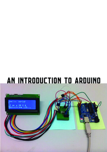
Arduino 101AN INTRODUCTION TO ARDUINOBY WOME N IN E NGINE E RINGFT T INA A ND AWE S O ME ME NTO R S
Overview Motivation Circuit Design and Arduino Architecture Projects Blink the LED Switch Night Lamp Servo Motor Servo Motor and Potentiometer Additional Resources
Why Arduino? Easy to use Open source Inexpensive way to prototype
Motivation
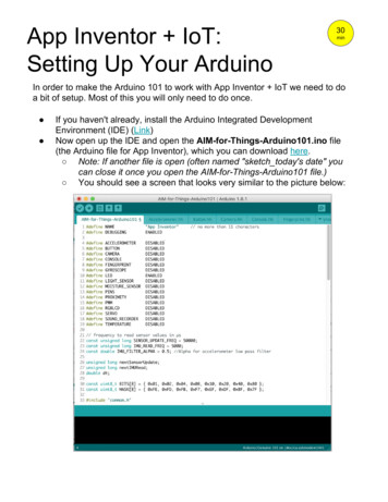
Arduino Low-powermicrocontroller, which is a mini chip containing aprocessor, memory, and input/output (I/O) componentsResetUSB PlugProcessor/MemoryExternal BatteryInput/output pins
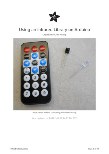
Embedded Systems Common place where microcontrollers are usedPhotoresistor,Switch,PotentiometerLEDs, MotorSketches*in the orange boxes are the examples we will go through today
BreadboardGroundPower(5V on Arduino)(GND on Arduino)
Project 1: Blink the LED (Hardware)You will need: 2 jumper wires resistors 1 LED
Project 1: Blink the LED (Hardware) LEDs Long leg ve terminal Short leg -ve terminal MUST be used with a resistor to limit the amount of current flowing through the LED,otherwise you might burn it out!
Project 1: Blink the LED (Hardware)Resistor (Ω) Can be connected either way What does the coloursmean? Note: In this workshop weare using 4-band resistors
Project 1: Blink the LED (Hardware)1. Choose a number between 4-13;connect a jumper wire from that slot2. Test the circuit with these resistors 150 Ω 1.5 kΩ3. Connect the ve terminal of LEDto the same row4. Ground the circuit
Arduino IDEBefore we start programming, open ArduinoSelect the type of microcontroller: Tools Board Select “Arduino Uno”Select the Serial Port in which theMicrocontroller is connected to: Tools Serial Port Select the serial port which Arduino isconnected to
Example – Turn on LEDThree parts to this example:1. Global variables: declaration and initialization int for integer boolean (true/false) string2. setup() Called when the sketch starts; only executed once Attach I/O pins (Sometimes) initialize timer, etc3. loop() Repeats infinitely as long as the board is powered andmemory is availableNote: Single line comment //; block comment /* */
Project 1: Blink the LED (Software)1. Before setup() Declare an integer variable to store the pin connected to LED. Syntax: int variableName yourNumber;2. setup(): initialize the pin as an output pin Syntax: pinMode(variableName, OUTPUT);3. loop(): delay(time); //where time is in milliseconds digitalWrite(variableName,STATE); //STATE HIGH (5V) or LOW (0V) HIGH LED on, LOW LED off4. Once you are done, press the arrow button to upload yourcode on Arduino!
Break
Project 2: Digital InputsHardware Components: Red LED, four wires, 150 Ω, and a dip switchSetup1. Connect one end of the switch to power, and the other end to ground2. Red LED and the 150 Ω resistor are in series (recall long and short legs)3. Long leg of red LED in series with resistor is connected to pin 5, and the short leg ofthe LED is connected to ground
Project 2: Digital Inputs Switches Completes the circuit when flip to ON
Project 2: Digital Inputs Before we go into the software, switch the connector from “5V” to pin 7Setup(): Initialize the LED pinInitialize pinMode of the switch to INPUT
Project 2: Digital Inputs if and else Actively checking if the condition specified in () is met If there are 2 conditions that are related, you can use If ( condition A) { } else if ( condition B ) {} // can have many else if else {} Notice that else does NOT have a condition statement
Project 2: Digital Inputs loop(): digitalRead( pin# ); digitalWrite( pin# , STATE ) Read input pin# and see if it is HIGH or LOWwrite STATE, which is either HIGH or LOW, to output pin#Step 2: A) if button is LOW, turn on LEDB) otherwise, if the button is HIGH turn off LEDRepeat A to B
Project 2: Digital Inputs ft Serial Monitor Serial communication to let you know when a button is pressed In setup: Serial.begin(9600);In loop: Serial.printIn(“Pressed Button”); //when the button is pressed write this to the serial monitorAfter uploading your code unto the ArduinoClick on the Serial Monitor button (Top right side of the IDE)
Project 2: Digital Inputs Pseudo Code Before setup() Initialize the LED and switch pins In setup() Attach pinMode LED OUTPUT switch INPUT In loop() If switch is ON LED ON else LED OFF
Project 3: Put it all together and more! Photoresistor Variable resistor that changesresistance based on light intensityDirection doesn’t matterWe can use Serial Monitor to checkthe ambient lighting condition! This will help to pick the thresholds forour project!!
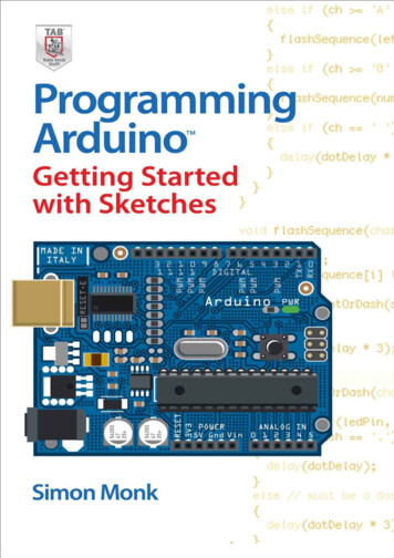
Project 3: Circuit1.Connect Photoresistor to A0 and the other end to 5V2.Connect a 10k Ω resistor from the rail from 1. toground3.Connect 3 pins of your choice to 3 LEDs of differentcolours4.Connect the LEDs to ground
Project 3: Timer millis() Returns the time since the program started running
Project 3: Write your own function Extract code from the main loop to keep it clean Avoid repeating the same line(s) 2 types of functions: void: don’t return anything e.g. turnLEDOn() int: function that returns an integer value e.g.: adder()
Project 3: Analog input/output Analog pins map input voltages between 0 and 5 volts into integer values between 0 and 1023 Arduino Uno has analog pins A0 – A5 Use analogRead( pin # ); // to read from the analog pin Use analogWrite (pin #, duty cycle); // to write to the pin
Project 3: Random generator Generate a random number (integer, long, etc) by reading noise from unused analog pin In setup, we need to create a randomSeed ( analogRead( pin # ) ); In loop, we generate number by doing random (min# , max #);
Project 3: Night lamp Pseudo Code variables: int: pins and constants unsigned long timer boolean variable setup(): Set pinMode Serial Motor Random generator
Project 3: Night Lamp Pseudo Code loop(): Get the value from the checkBrightness() function If the brightness threshold If led is on turn on led by calling function Update the Boolean variable Update the timer Else if it is time to change colour Turn the led on again by calling function Else Turn off the LED Update Boolean variable
Project 3: Functions Pseudo Code int getBrightness (): return the analog value from the photoresistor void turnLEDOff() analogWrite( pin #, 0 ); // to turn off the LEDs void turnLEDOn() Generate random values analogWrite( pin #, randomValue); // to set intensity of the LEDs
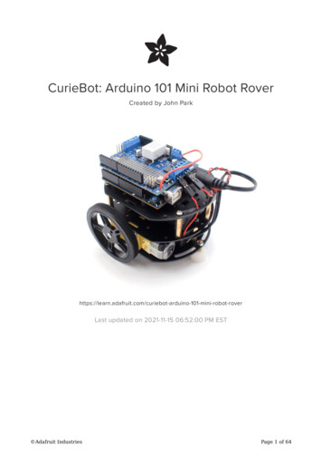
Switch GearsLet’s now look at the servo motor on Diyode CodeShieldThis piece of hardware handles the wiring for us! Servo motor comes with encoders, which allows us to identify the position ofthe motor Include these lines before your setup() #define SERVO 5 #include Servo.h
For loops Used when you need to repeat something for a known number of times
Arduino: Servo Class1. To control a servo using Arduino, we need to import the servo motor class: #include Servo.h 2. In our setup(), attach the servo pin to the Arduino myservo.attach(SERVO); //SERVO is the pin defined in the previous slide: #define SERVO 53. In loop(), to tell the motor to turn, use the function myservo.write(position); //position is an int variable, telling the motor how much to turn Stick a delay() function right after write()! delay(15); // in milliseconds
Project 4: Turn 180 then switch directionUsing the servo class (myServo.attach(), myServo.write()), delay(), and forloop, write a program Turn the motor from 0 to 180 Once reached 180 , turn the motor back to 0
Project 5: Servo Control - Potentiometer Potentiometer A variable resistor Resistance value changes based on the contact with the rotatable shaft E.g.: volume control, etc On the CodeShield #define POT 2Potentiometer (POT)
Project 5: Map(variable, a, b, c, d); The values from the potentiometer exceeds the range of the servo motor Use map() to scale up/down the range between a-b to fit the range of c-d For our purpose: variable input (i.e. the analog value from the potentiometer) a min value from the potentiometer (0 A) b max value from the potentiometer (1023 A) c min value to be mapped to (0 for the servo) d max value to be mapped to (e.g.: 180 )
Project 5: Servo Control Pseudo Code Before setup: Include the servo library Create a servo object Create an integer variable to store the input from the potentiometer setup(): Attach servo to the pin loop(): Read the analog input from the potentiometer; store it in the integer Map the input range to the range of the motor Write the position to the motor Delay()!!!
Bonus Want to create an Android Application communicate with Bluetooth checkthis out: Want to create a Matlab program/GUI using Arduino: Guide on How to Use App Inventor with ArduinoApp InventorMatlab: You want to get the hardware support packageSimulink: Get this support packageInterested about how the processing core works You want to check out: assembly languages (low-level programming language)Here is a neat tutorial on assembly language
Bonus Arduino Built-in Functions: http://arduino.cc/en/Reference/HomePageInterested about how the processing core works You want to check out: assembly languages (low-level programminglanguage)Here is a neat tutorial on assembly language
Bonus – Python with Arduino For those that wanna see how micro-controllers can be used to communicate with thecomputer. Install Python 2 (in specific Python 2.7.3)On Windows: using Python in the command prompt:1. Go to the Control panel in the start menu2. Click on System Properties control3. Go to “Environment Variables”4. Select "Path", and then in the bottom section (Systems Variables) select "Edit"5. At the end of the “Variable Value” without deleting any of the text already there, add thetext: ";C:\Python27"Install PySerial PySerial allows access to serial ports and automatically selects the appropriate back-end. For information onPySerial is available here.For all OS, download the .tar.gz install package for PySerial 2.6 from https://pypi.python.org/pypi/pyserial Thiswill give you a file called: pyserial-2.6.tar.gzDecompress the folder:Windows: Install 7zip to decompress the file.Mac or Linux: Open a Terminal session, and go to where you've downloaded pyserial-2.6.tar.gz andthen issue the following command to unpack the installation folder.
Image /95/introduction-to-embedded-systems-30-728.jpg?cb circuitdiagram en/uploads/Tutorial/ExampleCircuit iyode.com/igg/images/codeshield.png
Arduino: Servo Class 1. To control a servo using Arduino, we need to import the servo motor class: #include Servo.h 2. In our setup(), attach the servo pin to the Arduino myservo.attach(SERVO); //SERVO is the pin defined in the previous slide: #define SERVO 5