Transcription
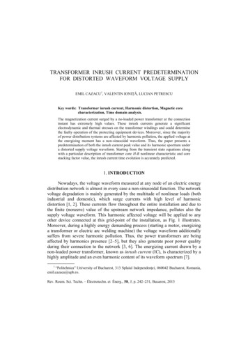
Elimination of Transformer Inrush Currentsby Controlled SwitchingPart I - Theoretical ConsiderationsJohn H. Brunke, Fellow, IEEEBonneville Power AdministrationVancouver, Washington, USAAbstract: Transformer inrush currents are highmagnitude, harmonic-rich currents generated whentransformer cores are driven into saturation duringenergization.These currents have undesirableeffects, including potential damage or loss-of-life tothe transformer, protective relay misoperation, andreduced power quality on the system. Controlledtransformer switching can potentially eliminate thesetransients if residual core and core flux transients aretaken into account in the closing algorithm. Thispaper explores the theoretical considerations of coreflux transients. Based on these studies algorithmswere developed which allow controlled energizationof most transformers without inrush current.Keywords: Inrush current, controlled switching,residual flux, transformer switching.Klaus J. Fröhlich, Senior Member, IEEESwiss Federal Institute of TechnologyZürich, SwitzerlandAlthough reductions in inrush current magnitudeshave been achieved with controlled closing, thepresent state of the art does not incorporate residualflux in the control algorithms, which results in nonoptimal energization [1].This paper will show that the effects of residual fluxcan be specifically included in determining anoptimal closing instant. This optimal closing cantheoretically result in the complete elimination ofinrush transients in many transformer core andwinding configurations. Part I of this paper presentsstrategies for controlled energization of large powertransformers based on theoretical considerations.Part II discusses practical aspects of controlledtransformer energization, including the limitations oftypical circuit breakers.I. IntroductionRandom power transformer energization can createlarge flux asymmetries and saturation of one or morewinding cores of the transformer. This saturationresults in high magnitude currents that are rich inharmonic content and have a high direct currentcomponent. These currents can cause false operationof protective relays and fuses, mechanical damage tothe transformer windings from magnetic forces, andgenerally reduce power quality on the system.The effects of these transients are normally mitigatedby de-sensitizing protective relays or over sizingfuses. Closing resistors have been used to reduce themagnitude of the inrush currents. Controlled closing,or controlling the point on the power frequencyvoltage wave where energization occurs, has alsobeen employed to reduce these inrush transients [1].II. Inrush TransientsPower transformers are operated with the peak coreflux at the “knee” of the transformer core's saturationcharacteristic. A typical core saturation characteristicis illustrated in Figure 1, where, as well known, thesinusoidal core flux is the integral of the appliedvoltage.The curve shown is a flux/current curve, and theslope at any point is proportional to the windinginductance. With only a modest flux increase beyondsaturation, or a symmetry shift of the flux, very highmagnitude current pulses will result as the slope, andtherefore the inductance, is very small in that regionof the curve (see Figure 1b).When a transformer is de-energized, a permanentmagnetization of the core remains due to hysteresisof the magnetic material. This “residual flux” isinfluenced by the transformer core materialcharacteristics, core gap factor, winding capacitance,circuit breaker current chopping characteristics andother capacitances connected to the transformer. Thecore flux and therefore residual flux can be measuredby integration of the winding voltage.
core flux is more than two times higher than the peaknormal core flux. The core has been driven far intosaturation. This asymmetrical saturation results inthe typical inrush current transient characterized by ahigh harmonic content and a direct currentcomponent.SaturationCharacteristicCore Fluxa)Although closing resistors have been employed toreduce these transients, the only way these transientscan be eliminated is to prevent the core saturation.This can be accomplished by controlling the instantof energization [2].MagnetizingCurrentIII. Transformer ModelingIn order to investigate core flux transient phenomenain transformers with various core and windingconfigurations a theoretical model was required.Transformer modeling, especially of transientphenomena, is a complicated proposition.Auniversal model good for all frequencies andmodeling all characteristics of the transformer is notavailable. In addition, the significant differences inparameters among various transformers make adetailed knowledge of the transformer parametersand characteristics a requirement. The requirementsfor the model to study core flux transients primarilyinclude a correct core flux/current relationship andthe ability to model residual core flux.Inrush Currentb)Figure 1. The flux/current (saturation) characteristicdetermines the magnitude of the magnetizing andinrush current for a) symmetrical and b)unsymmetrical core fluxes. Note: a) and b) havedifferent scale factors)The most commonly used transformer core modelutilizes a resistor, to represent losses, connected inparallel with an inductor that represents themagnetizing current [3]. Such a model does notallow for residual flux. Other methods using acurrent generator to represent residual flux functionin a single-phase model but are not applicable inthree-phase transformer models as they yield aneffective short circuit.When a transformer is energized the instantaneousmagnitude of core flux at the instant of energizationis the residual flux. The amount of offset of thesinusoidal flux generated by the applied voltage isdependent upon the point of the voltage wave wherethe transformer is energized. This is illustrated inFigure 2. The peak core flux Φ can therefore reach avalue of 2Φ normal Φ residual .Residual fluxΦIn order to accurately model the core, the “type 96hysteretical inductor” of the ElectromagneticTransient Program (EMTP) [3] was used. Thismodel follows a hysteresis characteristic to representthe core. In order to gather the necessary data toaccurately model the transformer, the BonnevillePower Administration (BPA) performed a field test.Comparison of simulations and the field test dataverified the model performance.The modelobviously has limitations, such as modeling the corecharacteristic only at one frequency, but this restraintis considered acceptable for this analysis.Transient FluxVoltageFLUXTimeNormal PeakCore FluxFigure 2. Core flux showing worst energization casefor this residual condition.IV. Controlled Switching of Single-PhaseTransformersIn the case of controlled closing of capacitors,optimal energization point is at the instant when theFor the most severe case shown in Figure 2, whereenergization was at a voltage zero, the peak transient2
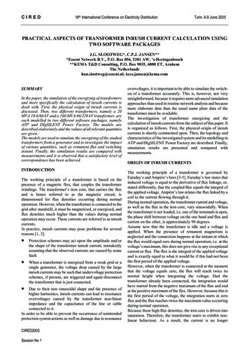
energized phase. The flux created in the cores of theother two phases is dynamic core flux.source voltage is equal to the trapped charge voltageon the capacitor. For the case of controlled closing oftransformers, the “trapped charge” has a parallel inthe residual flux. So the basic principle to eliminatethe core flux asymmetry, the “induced” flux (integralof the applied voltage) at the instant of energizationmust equal the residual flux [2]. There is of courseno induced flux before energization, but the sourcevoltage has the prospect to create an induced flux. Ifthe source voltage is considered as a virtual fluxsource, then the optimal instant to energize atransformer is when the “prospective” flux is equal tothe residual flux. This principle is shown in Figure 3.It provides the basic strategy for controlled closingon single phase transformers.VCore FluxTime1V/2Figure 4. A multiphase transformer with singlephase cores and a delta-connected windingdemonstrating the interaction of voltage and fluxes.The arrows show the phase relationship between thecore fluxes.Residual FluxFLUXV/2The core fluxes in all three phases therefore have thesame magnitude and phase relationships to each otheras the winding voltages. The dynamic core fluxes arealso 180 degrees out of phase and at one-half themagnitude as the flux in the fully energized phase. Inthese cases optimal energization can be achieved byenergizing the last two phases one-quarter cycle afterthe first phase, when the prospective flux and thedynamic core flux in each phase is equal [1]. Figure5 shows this situation.2Prospective FluxFigure 3. Optimal energization of a single-phasetransformer is shown. Optimal energization pointsexist at times (1) and alternate optimal time (2).0.80Flux, zero residualPhase BV. Controlled Switching in MultiphaseTransformers with No Residual FluxOnly transformers with single-phase cores and onlygrounded windings may be considered as threesingle-phase transformers, but most transformers onpower systems have interactions between the phases.In these other transformers, after one phase has beenenergized, the flux in the other cores or core legs isnot a static residual flux, but a transient flux, in thefollowing called “dynamic” core flux. Figure 4shows an example of a transformer with threeseparate cores connected by a delta winding.0.042.0Phase C46.050.054.058.0Tim e m s 1FluxkV-0.80Phase APhase AclosedPhases B& C closedFigure 5. Energization of a three-phase transformerwithout residual flux. Prospective and dynamic corefluxes for each phase are shown.First, assuming that the residual flux is zero in allthree phases, then the optimal instant for the firstphase to close is when the prospective flux is equal tozero. This instant is at a voltage peak. After the firstphase closes, a voltage is generated in each of theother two phases of the delta winding. Thesevoltages are each one half the magnitude and 180degrees out of phase of the voltage of the fullyThe optimal energization for a transformer with athree-phase core will be the same. In that situationthe flux generated by the energized phase willdirectly create dynamic fluxes in the other twophases. These dynamic fluxes will have the samecharacteristics as those induced by the delta windings(see Figure 4) described above.3
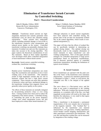
also significantly different. Therefore the voltage onthe windings is not divided evenly, i.e. the windingwith the largest inductance will have the highestvoltage. This higher voltage will create a higher fluxlevel, increasing the B-phase flux towards themagnitude of the C-phase flux. The result is that theflux in B and C phases rapidly equalizes andeliminates the effect of their residual flux. Thisphenomenon is referred to as “core fluxequalization.”VI. Residual FluxResidual core flux can assume values up to 85% ofpeak normal flux, although more typical magnitudesare in the range of 20 to 70%[4]. It can be shownthat the residual flux in cores of three-phasetransformers must inherently sum to zero, andtypically forms a pattern with near zero residual fluxin one phase and plus and minus some finite value inthe other two phases. This has been observed in theliterature and demonstrated in field tests [2].As already mentioned, in most three-phasetransformers, the flux in the main core legs sum tozero [5]. This is true for transformers with a threelegged core or a delta winding. It is not the case fortransformers without a delta-connected winding thatare single phase or have five-legged or shell-formcores. If one phase of a transformer which isconfigured such that fluxes sum to zero is energizedsuch that its core leg does not go into saturation, theflux in that phase is equal to its prospective flux atevery instant. Since the prospective fluxes and thecore fluxes must sum to zero, the induced dynamiccore fluxes must equal their prospective fluxes twotimes per cycle [2]. This is illustrated in Figure 7,where A-phase with zero residual flux is closed atpoint “A” and immediately induces dynamic fluxes inphase B and C.VII. Controlled Switching in Three-PhaseTransformers with Residual FluxFirst, for illustration, it is assumed that a typicalresidual flux pattern is formed in a transformer of theconfiguration shown in Figure 4, and the phase withzero residual (“A”) is energized at the optimal pointon wave (peak voltage and therefore zero prospectiveflux). The resulting dynamic core flux in the otherphases will not be divided evenly. The dynamicfluxes in Figure 6 start at their respective residualflux levels and move around their hysteresis loop inthe same direction. One phase (“C”) will reach the“knee” of the saturation characteristic while the otherphase (“B”) is still in the linear portion. As theslopes of the characteristics are significantly differentat this point, the inductances of the two windings areFluxA PhaseB PhaseC PhaseCurrentInitial ResidualFluxesFigure 6. Flux-current core characteristic showing how the effective inductance of the B and C phase windingsdepend upon the residual flux and the trajectory around the hysteresis loop. After phase A is energized, the dynamicflux in the other two phases results in an inductance difference causing rapid core flux equalization.4
0.80strategy.” This strategy is demonstrated in the testenergization of a laboratory transformer in Figure 8.Residual fluxes, 0%, -70%, 70%Dynamic core fluxesVII. Conclusions0.042.046.050.054.0In most three-phase transformers it is possible to useresidual flux measurements and controlled closing toeliminate transformer inrush transients.Threestrategies have been proposed for controlledenergization of multi-phases transformers.58.0Time ms0.800FLUXFlux kVs-0.80Prospective FluxesABB and C phases energizedCFigure 7. Prospective and dynamic core flux for athree-phase transformer with residual flux.Φ DcΦa0.0Φ DbDepending upon the polarities of the residual flux inthe two legs, the dynamic core flux and prospectivefluxes will be equal either at the point marked “B” or“C” in Figure 7. These points off
Abstract: Transformer inrush currents are high- magnitude, harmonic-rich currents generated when transformer cores are driven into saturation during energization. These currents have undesirable effects, including potential damage or loss-of-life to the transformer, protective relay misoperation, and reduced power quality on the system. ControlledFile Size: 255KBPage Count: 6