Transcription
Calculation of transformer inrush currents occurring during theenergizing of the Public Grid after a major black outCitation for published version (APA):Jansen, C. P. J., Slootweg, J. G., & Groot, de, R. A. C. T. (2005). Calculation of transformer inrush currentsoccurring during the energizing of the Public Grid after a major black out. In Proc.Power Tech, 2005 IEEERussia, St. Petersburg, 27-30 June 2005 9/PTC.2005.4524439Document status and date:Published: 01/01/2005Document Version:Publisher’s PDF, also known as Version of Record (includes final page, issue and volume numbers)Please check the document version of this publication: A submitted manuscript is the version of the article upon submission and before peer-review. There can beimportant differences between the submitted version and the official published version of record. Peopleinterested in the research are advised to contact the author for the final version of the publication, or visit theDOI to the publisher's website. The final author version and the galley proof are versions of the publication after peer review. The final published version features the final layout of the paper including the volume, issue and pagenumbers.Link to publicationGeneral rightsCopyright and moral rights for the publications made accessible in the public portal are retained by the authors and/or other copyright ownersand it is a condition of accessing publications that users recognise and abide by the legal requirements associated with these rights. Users may download and print one copy of any publication from the public portal for the purpose of private study or research. You may not further distribute the material or use it for any profit-making activity or commercial gain You may freely distribute the URL identifying the publication in the public portal.If the publication is distributed under the terms of Article 25fa of the Dutch Copyright Act, indicated by the “Taverne” license above, pleasefollow below link for the End User Agreement:www.tue.nl/taverneTake down policyIf you believe that this document breaches copyright please contact us at:openaccess@tue.nlproviding details and we will investigate your claim.Download date: 13. Jun. 2021
Calculation of Transformer Inrush Currentsoccurring during the Energizing of the PublicGrid after a major Black OutC.P.J. Jansen; J.G. Slootweg and R.A.C.T. de GrootAbstract—The paper describes simulations and a live test ofthe black-start procedure of an industrial power plant in theNorth of the Netherlands. After a total blackout of the PublicGrid in the Netherlands, the restoration process shall start withso-called black-start units. To increase the probability that there-energizing of the Public Grid indeed succeeds, the Dutchtransmission system operator obliges units to prove their blackstart capability by performing a live test.A crucial step in the re-energizing of the Public Grid is theenergizing of large transformers. Problems can be expected dueto the inrush current of the transformers. For one suchgenerating unit extended simulations of the inrush phenomena ofthe transformers and calculation of inrush currents andovervoltages were performed. Based on the simulation resultswell-founded decisions were made on the most suitable start-upprocedure. The simulations were followed by live tests of theblack-start procedure.Index Terms—Inrush Current; Grid Black Out; GridRestoration; Transformer Energizing.AI. INTRODUCTIONFTER a total blackout of the Public Grid, and separationof all connected power plants, the restoration processbegins by starting the generating units designated (orcontracted) as black-start units. Black-start units are capableof starting without external power supply. A black-start isusually performed with the aid of a diesel unit or a gas turbineunit to supply the auxiliary systems of the main unit. Oncerunning, the generating unit is connected to the Public Grid[1].A crucial step in the re-energizing of the Public Grid is theenergizing of the main unit's step-up transformer or the firstgrid (step-down) transformers. These grid transformers are ofsimilar or even higher rating than the generating unit.Problems can be expected due to the inrush current of thetransformers. These currents are large in amplitude, areThis work is done by KEMA T&D Consulting and Essent Netwerk B.V.and was supported by Delesto B.V. and by TenneT bv, the DutchTransmission System Operator.C. P. J. Jansen and R. A. C. T. de Groot are with KEMA T&D ConsultingArnhem, The Netherlands (e-mail: kees.jansen@kema.com).J. G. Slootweg is with Essent Netwerk B.V. ’s-Hertogenbosch, TheNetherlands (e-mail: han.slootweg@essent.nl ).strongly non-sinusoidal and can last for several minutes.There is a risk that protection devices respond to thesecurrents, causing the generating unit to trip. In addition,resonance overvoltages can occur caused by the transformernon-linear impedance and the line or cable capacitancetogether with the weak damping of the system [2], [3].One way to energize the transformers is by performing aso-called soft start of the complete circuit generator-step-uptransformer-grid transformer. For a soft start, first theconnections between generator and transformers are made.Then the generator is started without excitation voltage. If thegenerator runs at no load and full speed, the excitation currentof the generator is increased. The gradual increase of theapplied voltage avoids inrush currents. Drawback is that theprocedure deviates from the normal start-up procedure of theunit and also affects the protection scheme and possibleinterlocks.To increase the success rate of the re-energizing of thePublic Grid after a total black out, the Dutch transmissionsystem operator (TenneT) obliges contracted generating unitsto prove their black-start capability by performing a live test.For one such generating unit, an industrial power plant inthe North of the Netherlands, extended simulations of theinrush phenomena of the transformers and calculation ofinrush currents and overvoltages were performed. Based onthe simulation results, well-founded decisions were made onthe most suitable start-up procedure. The simulations werefollowed by live tests of the black-start procedure.II. ORIGIN OF INRUSH CURRENTSThe working principle of a transformer is governed byFaraday’s and Ampère’s laws [4-6]. Faraday’s law states thatinduced voltage is equal to the derivative of flux linkage, or,stated differently, that the coupled flux equals the integral ofthe applied voltage. Ampère’s law relates the flux linked by acoil to the current flowing through it.During normal operation, the transformer current andvoltage, as well as the flux in the iron core, vary sinusoidally.When the transformer is not loaded, i.e. one of the terminals isopen, the phase shift between voltage on the one hand andflux and current on the other, is approximately 90 degrees.Assume now that the transformer is idle and a voltage is
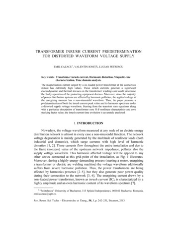
TABLE IGENERATOR ueGen 1Gen 234.08 MVA 50 MVA10.5 kV10.5 kV0.10 p.u.*0.10 p.u.*1.481 mp.u. 1.317 mp.u.2.007 p.u.1.910 p.u.0.194 p.u.0.226 p.u.0.131 p.u.0.151 p.u.1.8 p.u.*1.72 p.u.*Xq n 1Gen 20.5 p.u.*0.5 p.u.*0.131 p.u.* 0.151 p.u.0.075 p.u.0.085 p.u.6,54 s5.49 s0,04 s*0.018 s0,50 s*0.04 s*0,15 s*0,15 s*TABLE IITRANSFORMER PARAMETERSQuantitySnomUHVULVUkPCuP0, 100%I0, 100%Transformer 1, 220 MVA66 kV10.6 kV14.7 %87.6 kW10.3 kW0.77 mp.u.34.0 MVA10.5 kVValueTransformer 350 MVA70.5 kV10.5 kV11.0%116 kW31.3 kW2.3 mp.u.Transformer 4160 MVA220 kV66 kV17.8 %459 kW71.4 kW1.04 mp.u.20.0 MVA10.6/66.0 kV20.0 MVA66.0/10.6 kVTransformer 1Transformer 210.5 kV66.0 kV10.5 kVSystem aIII. MODELING50 MVA10.5/70.5 kV G50 MVA10.5 kV160 MVA66.0/220.0 kVTransformer 310.5 kVTransformer 420.0 MVA10.6/66.0 kV34.0 MVA10.5 kV220.0 kV GA. System descriptionThe systems studied in this paper consist of transformersand generators in island operation, as depicted in figure 1. Thegenerators have a rating of 34 MVA and 50 MVA at a voltageof 10.5 kV. The first generator is connected to a 66 kV busbarthrough a 20.0 MVA 10.6/66 kV transformer. It is driven by agas turbine. The second generator is connected to the same66 kV busbar through a 50 MVA transformer and is also a gasturbine unit.To investigate the inrush phenomenon and to validate thedeveloped models, firstly a second 20.0 MVA 10.6/66 kVtransformer is connected to the 66 kV busbar (system a infigure 1). In the next case also a 160 MVA 66/220 kVtransformer is connected to this 66 kV busbar (system b infigure 1). In the first case, only one generator is in operation,whereas in the second case, both are in operation. The relevantparameters of the generators are given in table I and of thetransformers in table II.The parameters not given in the generator documentation havebeen estimated and are marked with *. The one-line diagramsof the systems are depicted in figure 1.The generators and transformers were each modeled in twodifferent software packages, namely ATP and DIgSILENTPower Factory.Quantity Gapplied. When the presence of remanent magnetism isneglected and the connection happens at the instant at whichthe flux would equal zero during normal operation, i.e. at thevoltage’s maximum, this does not give rise to any exceptionalcurrent or flux. The flux is the integral of the applied voltageand is exactly equal to what it would be if this had not beenthe first period of the applied voltage.However, when the transformer is connected at the momentthat the voltage equals zero, the flux will reach twice itsnormal height when integrating the voltage. Had thetransformer already been connected, the integration wouldhave started from the negative maximum of the flux and endat the positive maximum of the flux. However, because this isthe first period of the voltage, the integration starts at zero fluxand the flux reaches twice the maximum value occurringduring normal operation.Because these high flux densities, the iron core is driveninto saturation. Therefore, the transformer starts to exhibitnon-linear behavior. As a result, the current is no longerapproximately proportional to the flux. Instead, much morecurrent is needed to increase the flux and the current caneasily reach much more than two times its maximum. Thislarge current is referred to as the inrush current. As statedearlier, inrush currents can lead to undesirable effects, such asthe triggering of protection devices and resonant overvoltages.The presence of remanent magnetism can increase this effect,leading to even larger inrush currents.Transformer 110.5 kV66.0 kVSystem bFig. 1. Investigated systems a and bB. ATP ModelThe ATP model was developed using ATPDraw. Thegenerators were modeled as synchronous generators using themodel SM59 for which all relevant parameters are given intable I. The transformers were modeled using the BCTRANdialog box. For those transformers connected directly to thegenerators, which were assumed to be already energized at thestart of the simulation, all nonlinearities were neglected. Incase of the transformer to be energized, the non-linear
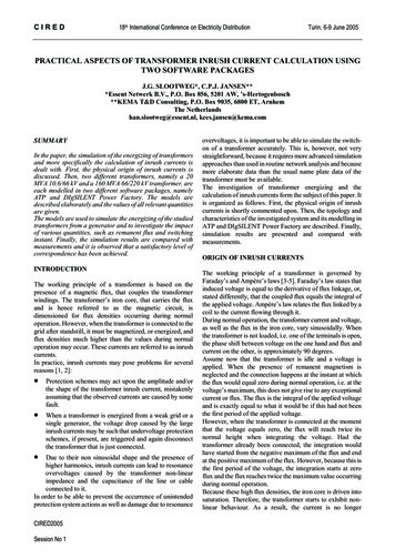
behavior was modeled using the pseudo-nonlinear hystereticinductor component Type 96 [7].The Φ-I characteristic of the nonlinear inductor provedcritical for matching the simulation results with themeasurements. However, it was unfortunately not availablefor the investigated transformers. Therefore, it was calculatedusing the supporting routine HYSDAT that comes with ATP.The values for Φ and I to be inserted in HYSDAT werederived using the “View ” function of the BCTRAN dialogbox. It was assumed that the positive saturation point, to beinserted in HYSDAT, lied at a voltage of 1.18 p.u., and thecorresponding no-load current was assumed to equal 10 timesthat at a voltage of 1.1 p.u. The assumption of a factor 10increase in the current was based on measurements taken fromone of the transformers, of which no-load measurements up toa voltage of 1.18 p.u. were available. These were used toextrapolate the value for the other transformers of which onlymeasurements up to a voltage of 1.1 p.u. were available.C. Power Factory ModelIn Power Factory the generators were modeled using thestandard synchronous machine model. The parameters for thegenerators are given in table I. The transformer model inPower Factory used for the inrush simulations, is the twowinding transformer model shown in figure 2 [8]. The modelcontains the leakage reactances at the low and high voltageside together with the winding resistance at low and highvoltage side. The model also shows the magnetizing reactanceXm and the ion losses resistance iMFig. 3. Flux saturation model in Power FactoryIV. SIMULATION RESULTS AND MEASUREMENTSA. Simulation resultsNow, simulation results obtained with the models describedearlier are presented. Figure 4 shows simulation resultsobtained with ATP and Power Factory. It shows the phasecurrents for the switching of the 20.0 MVA transformer(transformer 2 of system a in figure 1).200[A]150100500-50-100UsecUprimXMRFen1 : n2-150-2000.0150.0350.055(f ile SW 20 2.pl4; x-v ar t) c:X0055C-X0051C0.075c:X0055A-X0051A0.095[s] 0.115c:X0055B-X0051BFig. 2. Transformer model in Power Factory200.0To model the effect of inrush currents, the magnetizingreactance must be modeled as a function of the magnetizingcurrent. For that, the magnetic flux is given as a function ofthe magnetizing current in figure 3.The unsaturated part of the curve is determined by thesimulation software from the no-load characteristics of thetransformer. The saturated part and also the knee flux, thenormal operating point of the transformer, is given by the Φ-Icharacteristic of the transformer. As already mentioned, thischaracteristic was not known for the transformers. For theknee flux a typical value 1.04 p.u. is used.
large current is referred to as the inrush current. As stated earlier, inrush currents can lead to undesirable effects, such as the triggering of protection devices and resonant overvoltages. The presence of remanent magnetism can increase this effect, leading to even larger inrush currents. III. MODELING A. System description The systems studied in this paper consist of transformersCited by: 4Publish Year: 2005Author: C.P.J. Jansen, J.G. Slootweg, R.A.C. de Groot