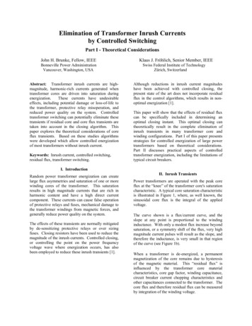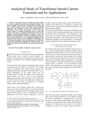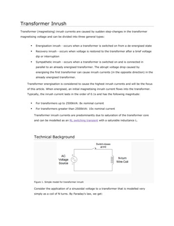
Transcription
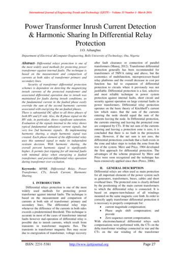
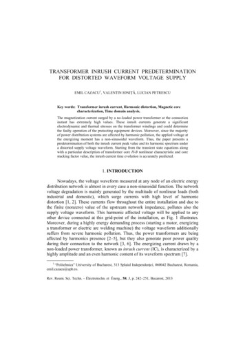
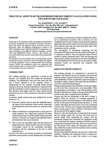
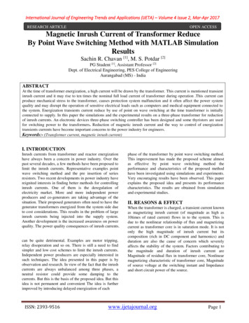
Transformer InrushTransformer (magnetising) inrush currents are caused by sudden step-changes in the transformermagnetising voltage and can be divided into three general types: Energisation inrush - occurs when a transformer is switched on from a de-energised state Recovery inrush - occurs when voltage is restored to the transformer after a brief voltagedip or interruption Sympathetic inrush - occurs when a transformer is switched on and is connected inparallel to an already energised transformer. The abrupt voltage drop caused byenergising the first transformer can cause inrush currents (in the opposite direction) in thealready energised transformer.Transformer energisation is considered to cause the highest inrush currents and will be the focusof this article. When energised, an initial magnetising inrush current flows into the transformer.Typically, the inrush current lasts in the order of 0.1s and has the following magnitude: For transformers up to 2500kVA: 8x nominal current For transformers greater than 2500kVA: 10x nominal currentTransformer inrush currents are predominantly due to saturation of the transformer coreand can be modelled as an RL switching transient with a saturable inductance L.Technical BackgroundFigure 1. Simple model for transformer inrushConsider the application of a sinusoidal voltage to a transformer that is modelled verysimply as a coil of N turns. By Faraday's law, we get:
Whereis the voltage amplitude (V)is an arbitrary switching angle (radians)is the number of turns in the transformer coilis the transformer magnetising fluxTo solve this differential equation for flux given some initial (residual) flux, we take the Laplace transform of it:Solving for:Simplifying further:Taking the inverse Laplace transform, we finally get:(1)While this is a gross simplification of reality, the equation above can give us some intuition about thenature of the transformer flux during a transient switching on (energisation) event.Effects of Switching AngleFrom equation (1) above, it can be shown that the switching angle results in a dc offset of the fluxwaveform. The figure below shows the effects of the switching angle on the flux waveform at threeangles (relative to the ac supply voltage): 1) a positive zero crossing (θ 0), 2) a voltage peak () and 3) a negative zero crossing (θ π).
Figure 2. The effects of switching angle on fluxHere it can be seen that switching at a positive zero crossing shifts the flux waveform up to a peakflux of 2pu (and vice versa for a negative zero crossing, i.e. peak flux down to -2pu). There is no dcoffset when switching at a voltage peak. Any other switching angle will result in a dc offset in betweenthe zero crossing waveforms.Effects of Residual FluxIt can be readily seen from transient flux waveform in equation (1) that the residual flux causes a dcoffset in the flux waveform, i.e. a positive residual flux offsets the waveform up and vice versa for anegative residual flux.Therefore, depending on the switching angle, a residual flux can actually be beneficial to keepinginrush currents low. For example, if the switching angle was a negative zero crossing (e.g. θ π, thiswould offset the flux waveform down. But a positive residual flux would have the opposite effect byoffsetting the flux waveform up.On the other hand, the residual flux can reinforce the dc offset caused by the switching angle and canresult in peak flux values (absolute) well over 2pu.Transient Flux in Practical TransformersIn our idealised model above, the transient flux waveform on switching has constant dc offsetsdepending on the switching angle and residual flux. However in a practical transformer, the effect ofleakage impedances (i.e. winding resistances and leakage reactances) will lead to an exponentiallydecaying dc offset component (like in the switching of RL circuits), with the rate of decay dependingon the time constant.
The figure below presents a more realistic transient flux waveform on switching, displaying a decayingdc component:Figure 3. Example of transient flux waveform in practical transformersNon-Linear Relationship between Flux and CurrentFigure 4. Flux-current hysteresis loopWe saw above that during transient conditions, the magnetising flux can rise up over 2pu (dependingon the switching angle and residual flux). The other key factor that leads to high inrush currents is thenon-linear relationship between flux and current.The transformer core exhibits saturation characteristics like the hysteresis loop in the figure shown onthe right. Here it can be seen that at 1 pu flux, the core is already saturating and the slope of thecurve begins to approache a horizontal line. Therefore, if the flux is increased further above 1 pu flux,the current drawn can be several orders of magnitude higher.
SummaryPutting all the pieces together, the general intuition explaining transformer energisation inrush can beput as follows:1) On the sudden application of a voltage to the transformer (i.e. circuit breaker is closed), atransient flux waveform is generated that, depending on the switching angle and residual flux,can reach a peak of over two times nominal flux.2) The relationship between flux and current is highly non-linear. At higher than nominal flux,the core will begin to saturate and the related magnetising currents can get very high. This isequivalent to saying that as the core saturates, the magnetising reactance decreasessignificantly.References[1] Greenwood, A., "Electrical Transients in Power Systems", Wiley, x.php?title Transformer Inrush
Transformer Inrush Transformer (magnetising) inrush currents are caused by sudden step-changes in the transformer magnetising voltage and can be divided into three general types: Energisation inrush - occurs when a transformer is switched on from a de-energised state
