Transcription
FACSymphony A1Flow CytometerUser's Guide23-23437-002021-06For Research Use Only
CopyrightsNo part of this publication may be reproduced, transmitted, transcribed, stored inretrieval systems, or translated into any language or computer language, in any formor by any means: electronic, mechanical, magnetic, optical, chemical, manual, orotherwise, without prior written permission from BD.The information in this guide is subject to change without notice. BD reserves the rightto change its products and services at any time. Although this guide has been preparedwith every precaution to ensure accuracy, BD assumes no liability for any errors oromissions, nor for any damages resulting from the application or use of thisinformation. BD welcomes customer input on corrections and suggestions forimprovement.TrademarksBD, the BD Logo, FACS, FACSClean, FACSDiva, FACSFlow, FACSymphony, and Horizonare trademarks of Becton, Dickinson and Company or its affiliates. All othertrademarks are the property of their respective owners. 2021 BD. All rights reserved.Alexa Fluor and Pacific Blue are trademarks of Life Technologies Corporation.Cy is a trademark of GE Healthcare. Cy dyes are subject to proprietary rights of GEHealthcare and Carnegie Mellon University, and are made and sold under license fromGE Healthcare only for research and in vitro diagnostic use. Any other use requires acommercial sublicense from GE Healthcare, 800 Centennial Avenue, Piscataway, NJ08855-1327, USA.Laser safety informationClass 1 Laser Product.Regulatory informationFor Research Use Only. Not for use in diagnostic or therapeutic procedures.FCC informationWARNING: Changes or modifications to this unit not expressly approved by the partyresponsible for compliance could void the user’s authority to operate the equipment.NOTICE: This equipment has been tested and found to comply with the limits for aClass A digital device, pursuant to Part 15 of the FCC Rules. These limits are designedto provide reasonable protection against harmful interference when the equipment isoperated in a commercial environment. This equipment generates, uses, and canradiate radio frequency energy and, if not installed and used in accordance with the
instruction manual, may cause harmful interference to radio communications.Operation of this equipment in a residential area is likely to cause harmfulinterference in which case the user will be required to correct the interference at his orher own expense. Shielded cables must be used with this unit to ensure compliancewith the Class A FCC limits. This Class A digital apparatus meets all requirements ofthe Canadian Interference-Causing Equipment Regulations. Cet appareil numériquede la classe A respecte toutes les exigences du Réglement sur le matériel brouilleur duCanada.HistoryRevisionDateChange made23-23437-002021-06Initial release
Contents1 ABOUT THIS GUIDE9What this guide covers10Conventions10About the BD FACSymphony A1 documentation11Instrument technical support112 INTRODUCTION13System overview14Cytometer overview15Control panel17Fluidics system18Sheath and waste tanks25Optics26Workstation283 CYTOMETER SETUP29Starting the cytometer and computer30Preparing the sheath tank31Removing air bubbles34Preparing the waste tank36Preparing the fluidics39About the optical filters and mirrors40Custom configurations and baselines424 MAINTENANCE45Maintenance overview46Cleaning the fluidics47Shutting down the cytometer48Flushing the system49Replacing the waste tank cap50Changing the sheath filter52
6BD FACSymphony A1 Flow Cytometer User's GuideChanging the Bal seal56Changing the sample tube O-ring59Cleaning or replacing the sheath gasket60Accessing the red laser detector array615 OPTIMIZING CYTOMETER SETTINGS63Cytometer settings workflow64Verifying the configuration and user preferences65Running a performance check67Setting up an experiment70Creating application settings75Recording compensation controls77Calculating compensation806 RECORDING AND ANALYZING DATA83Data recording and analysis workflow84Preparing the workspace85Recording data86Analyzing data88Reusing an analysis937 TECHNICAL OVERVIEW95About fluidics96About optics97About electronics8 TROUBLESHOOTING104109Cytometer troubleshooting110Electronics troubleshooting1169 DETECTOR ARRAY CONFIGURATIONS119Fluorescence spectra120About configuration maps122About configurations122Base configuration polygon maps123
Contents10 SMALL PARTICLE DETECTOR129Preparing the system for small particle detection130Confirming small particle detection131Aligning the small particle detector137Small particle detector troubleshooting13911 SUPPLIES AND CONSUMABLES141Ordering 1457
1About this guideThis chapter covers the following topics:lWhat this guide covers (page 10)lConventions (page 10)lAbout the BD FACSymphony A1 documentation (page 11)lInstrument technical support (page 11)
10BD FACSymphony A1 Flow Cytometer User's GuideWhat this guide coversThis guide describes the procedures necessary to operate and maintain yourBD FACSymphony A1 flow cytometer. Because many cytometer functions arecontrolled by BD FACSDiva software, this guide also contains information aboutsoftware features required for basic cytometer setup and operation.This guide assumes you have a working knowledge of basic Microsoft Windows operation. If you are not familiar with the Windows operating system, see thedocumentation provided with your computer.ConventionsIntroductionThe following table lists the safety symbols used in this guide to alert you to potentialhazards.Safety symbolsSymbolMeaningCaution! Identifies a hazard or unsafe practice that could result in data loss,material damage, minor injury, severe injury, or deathBiological hazardElectrical hazardLaser hazard
Chapter 1 About this guideAbout the BD FACSymphony A1documentationIntroductionThis topic describes the documentation available with the BD FACSymphony A1 flowcytometer.Documentation USB CardThis user's guide is provided in PDF format on the Documentation USB card. TheBD FACSymphony A1 Flow Cytometer Site Preparation Guide is also on the card. Itcontains specifications for:oCytometer weight and sizeoTemperatureoElectrical requirementsHelp systemThe help system installed with BD FACSDiva software includes the documents listedbelow. Access the BD FACSymphony A1 help system from the Help menu in theBD FACSDiva software. Internet access is not required to use the help system.The help system includes the following documents:llBD FACSDiva Software Reference Manual: Includes instructions or descriptions forinstallation and setup, workspace components, acquisition controls, analysis tools,and data management. Access this manual from the BD FACSDiva Software Helpmenu (Help Documentation Reference Manual), or by double-clicking theshortcut on the desktop.BD Cytometer Setup and Tracking Application Guide: Describes how to use theBD Cytometer Setup and Tracking (CS&T) features in BD FACSDiva software.Instrument technical supportIntroductionThis topic describes how to get technical assistance.11
12BD FACSymphony A1 Flow Cytometer User's GuideContacting technical supportIf technical assistance is required, contact your local BD Biosciences customer supportrepresentative or supplier.When contacting BD Biosciences, have the following information available:lProduct name, part number, and serial numberlVersion of BD FACSDiva software you are usinglAny error messageslDetails of recent system performanceTo contact customer support:1. Go to bdbiosciences.com.2. Select your region. You will see information in your local language.3. Click Go.4. Click the Support link for details for your local region.
2IntroductionThis chapter covers the following topics:lSystem overview (page 14)lCytometer overview (page 15)lControl panel (page 17)lFluidics system (page 18)lSheath and waste tanks (page 25)lOptics (page 26)lWorkstation (page 28)
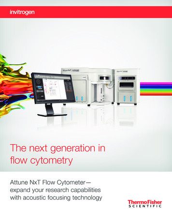
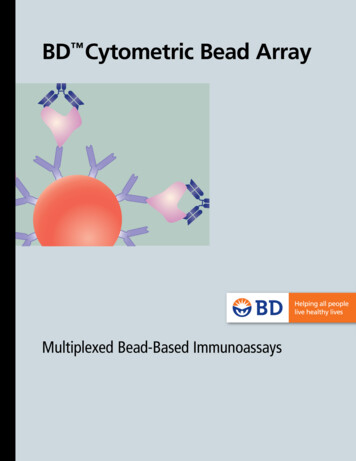
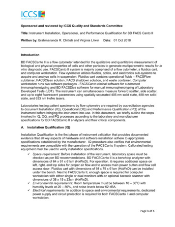
14BD FACSymphony A1 Flow Cytometer User's GuideSystem overviewAbout the systemThe BD FACSymphony A1 system includes the BD FACSymphony A1 flowcytometer, BD FACSDiva software running on the system workstation, the optionalBD FACSFlow supply system (FFSS), and the optional BD High Throughput Sampler(HTS). Each component is described in detail in the following sections.In addition, the BD Small Particle Detector (SPD) is an optional side scatter detectoroptimized to improve resolution of small particles such as extracellular vesicles. Formore information, see Small Particle Detector (page 129).TM12NumberComponents1Sheath and waste tanks2BD FACSymphony A1 flow cytometer3Computer workstation3
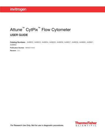
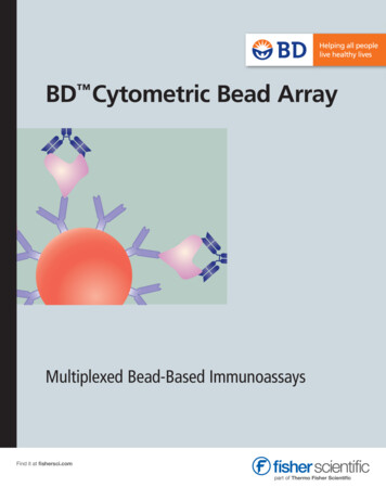
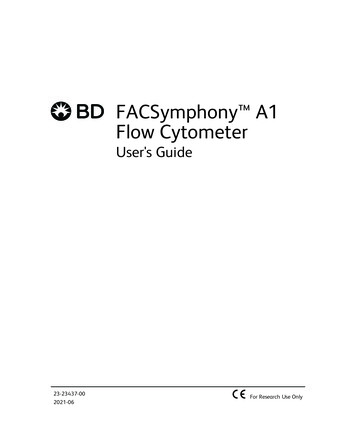
Chapter 2 IntroductionCytometer overviewIntroductionThe BD FACSymphony A1 flow cytometer is an air-cooled multi-laser benchtop flowcytometer with the ability to acquire 14 or 16 fluorescent parameters. It usesfixed-alignment lasers that transmit light through a flow cell to collect and translatethe resulting fluorescence signals into electronic signals. Cytometer electronicsconvert these signals into digital data.ComponentsThe following figures show the main components on the front and right side of theBD FACSymphony A1 flow cytometer. The descriptions are listed in the tables.1TM2345NumberComponent1Heat ventilation slots (top)2Control panel15
16BD FACSymphony A1 Flow Cytometer User's GuideNumberComponent3Sample injection port (SIP)4Heat ventilation slots (left side)5Optics access door (polygon detector rk 1Sheath LevelNetwork 2Waste Level3USB6CAUTION:Xxxxxxxxxxxxx xxxxx6ATTENTION:Xxxxxxxxxxxxxx xxxxxxxx xxxxxxxxxXXXXXXXXXxxx xxxxx xxxxxx xxxx xxxxxx xxx d laser detector array access panel2Power button3Electrical plug4Fluidic sensor ports5Air and fluidic ports6USB port for Small Particle Detector to workstation
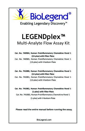
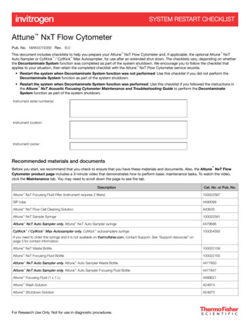
Chapter 2 IntroductionCaution! Do not place any objects on top of the instrument. Blocking the ventilationmay cause the instrument to overheat.Caution: Electrical Hazard! Do not place liquids on top of the instrument. Any spillof liquid into the ventilation openings could cause electrical shock or damage to theinstrument.Control panelOverviewThe fluidics display controller enables the monitoring of the sheath tank level, wastetank level, and air pressure status through a combination of status LEDs and textdisplay. It also controls sample flow rate and fluidic controls.The following figure shows the components in the control panel, which are listed in thetable.123645NumberComponent1System status and activity bar2Fluid control buttons3Sample flow rate buttons17
18BD FACSymphony A1 Flow Cytometer User's GuideNumberComponent4Sample fine adjust buttons5MODE button6Touch screen and status displayMore informationlFluidics system (page 18)lOptics (page 26)Fluidics systemIntroductionThe fluidics system carries the sample out of the sample tube and into theinterrogation region of the flow cell. Cells are carried in the sample core stream insingle file and measured individually.Note: If your system has the BD HTS option, see the BD High Throughput SamplerUser’s Guide for additional information on the sample flow rates and fluidic controls.System indicatorsThere are two system indicators (System Status and Activity) on the control panel aswell as Sheath Tank Air Pressure, Sheath, and Waste indicators on the graphic display.lSystem Status bar. Shows the status of the system by displaying a green, yellow, orred LED indicator. The following table describes the LED indicators, conditions thattrigger them, and any action that must be taken.LEDStatusActionConditionGoodNoneGoodCheck tank levelsSheath low and/orwaste nearly fullcolorGreenYellowCaution! Sheath and/orwaste tanks need attention.
Chapter 2 n! Take immediateaction.lllEmpty wastetankSheath emptyand/or waste fullFill sheath tankAir pressure is out ofspecificationCheck airpressureSystem status is also displayed on the Status screen. See Status screen (page 21)for a description of the Status screen.lActivity. Shows whether the cytometer power is on and the status of acquisition.The following table describes the indicator LEDs, and status that triggers them.IndicatorLED colorStatusSteady pulseblueCytometer is powered onFluctuatesblueForward scatter is registering cells or particlesFluid controlThe three fluid buttons (RUN, STANDBY, and PRIME) control the fluidics subsystem.lRUN Pressurizes the sample tube to transport the sample through the sampleinjection tube and into the flow cell.The RUN button is green when the sample tube is on and the support arm iscentered and the sample tube is pressurized. When the tube support arm is movedleft or right to remove a sample tube, the cytometer switches to an automaticstandby status to conserve sheath fluid, and the RUN button changes to orange.The RUN button will also turn orange if the sample tube is cracked or the BAL seal isbad. See Troubleshooting (page 109).lSTANDBY Stops fluid flow to conserve sheath fluid.When you leave the cytometer for more than a few minutes, place a tubecontaining less than 1 mL of deionized (DI) water on the sample injection port (SIP)and press STANDBY.lPRIME Prepares the fluidics system by draining and filling the flow cell with sheathfluid.Note: Remove sample tubes during the prime cycle.19
20BD FACSymphony A1 Flow Cytometer User's GuideThe fluid flow initially stops, and pressure is reversed to force fluid out of the flowcell and into the waste container. After a preset time, the flow cell fills with sheathfluid at a controlled rate to prevent bubble formation or entrapment. Atcompletion, the cytometer switches to standby mode.Sample flow rate controlThe three flow rate buttons (LOW, MED, HIGH) control the sample rate through theflow cell. The three fluidic control buttons (RUN, STANDBY, PRIME) enable you tocontrol the sample acquisition rate.12NumberComponent1Sample flow rate buttons2Sample fine adjust buttonsWhen sample adjust is set to 250 (as shown on the status screen on the control panel)the sample flow rates at the Low, Med, and High settings are approximately 12, 35,and 60 µL/min of sample, respectively. Each time you press one of the SAMPLE ADJbuttons, the fine adjust of the indicated sample increases or decreases by 10. Thefollowing table shows the approximate sample flow rate range for low, medium, andhigh.SettingsSample flow rate (µL/min)Low6–24Med17.5–70High30–120
Chapter 2 IntroductionStatus screenThe status screen display is a touchscreen color LCD screen which displays operationaldata while the system is running and toggles between two different displays: NormalMode and Setup Mode.Normal Mode displays the current settings of the Fine Adjust Potentiometer, the threeprogrammable potentiometer Set Points, Sheath Tank Pressure Status, Sheath Level,and Waste Level while the system is running.The Normal Mode screen is shown in the following illustation.FINE ADJUSTPRESSURE23SHEATHWASTEHIGH1GOODLOWSETPOINT 1SETPOINT 24SETPOINT 3SETPOINTFUNCTIONSETUPMODE567NumberDefinition1Fine Adjust. Shows the current setting of fine adjust. The slider enables quickchanges to the potentiometer setting by moving the slider up or down. Fine adjustcan be set in increments of 10 from 0 to 500. The normal set point is 250. Thelast value persists, even after cytometer shutdown.2Sheath Level. Shows range from 0 to 100. The display line decreases from top tobottom in sequences of 20% from full level. System status turns yellow at 20%,and red at 0%.3Waste Level. Shows range from 0 (empty) to 100 (full). The display lineincreases from bottom to top in sequences of 20%. System status turns yellow at80%, and red at 100% full.21
22BD FACSymphony A1 Flow Cytometer User's GuideNumberDefinition4Setpoint. Stores up to three potentiometer setpoints. A setpoint is set by tappingthe Setpoint Function button, moving the Fine Adjust slider up or down to thedesired point, and tapping one of the setpoint buttons. The Setpoint enables youto store three different settings and quickly change between them.5Setpoint Function. Button enables the setting of a Setpoint.6Setup Mode. Button to enter Setup Mode (Setup Mode can also be entered bypushing the Mode button on the control panel).7Alarm Silenced Indicator. When the alarm sounds are silenced, the indicator willturn on and display the text Alarm Silenced.Setup Mode displays the current settings of Sound, FFSS Mode, and Altitude while thesystem is running. The Setup Mode screen is shown in the following SS100050040-500SW Revision Ø6OFFEXIT SETUP3NumberDefinition1Sound. Turns the warning alarm sounds on or off. To turn on the alarm, slide theslider to the left position. To turn off the alarm, slide the slider to the rightposition. A green light indicates the alarm is active. A red light indicates thealarm is inactive.2FFSS Mode. Turns FFSS Mode on or off. To turn on FFSS Mode, slide the slider tothe left position. To turn off FFSS Mode, slide the slider to the right position. Agreen light indicates FFSS Mode is active. A red light indicates FFSS Mode isinactive.3Exit Setup. Button to exit Setup Mode.
Chapter 2 IntroductionNumberDefinition4Altitude. Shows the current setting of Altitude. The slider enables quick changesto the Altitude setting by moving the slider up or down. Altitude can be set from(-500 to 2000) meters. Sliding the slider down to the Off position turns the airpressure warning off.Fluidic alarms and the Mode buttonThe fluidic alarms are triggered by the waste and sheath fluid levels in the tanks andby low or high sheath tank air pressure levels. The alarms sound when the waste tank isnearly 100% full and the sheath tank is empty. The fluidic alarms and system statuswill also show warnings when you start up the cytometer until the tank pressurereaches the correct level.To silence the alarm sounds, press the Setup Mode in the touchscreen. Slide the Soundslider to the right. To turn the alarm sounds back on, slide the Sound slider to the left.If the alarm sounds are turned off, the Normal Mode screen will also indicate thesounds are off.Caution! Turning off the Sound may result in overflow of waste and you may runout of sheath.Note: The system status indicators are not affected by the alarm sounds on/off state.Note: When the cytometer is in FFSS mode, both visual and audible alarms aredeactivated.Note: The function of the system is sensitive to air pressure for flow rates. The systemneeds to know the altitude, in meters, of the location of the system in order toaccurately report the air pressure.Sample injection port (SIP)The SIP is where the sample tube is installed. The SIP includes the sample injectiontube (SIT) and the tube support arm. Samples are introduced through a stainless steelinjection tube equipped with an outer droplet containment sleeve. The sleeve works inconjunction with a vacuum pump to eliminate droplet formation of sheath fluid as itbackflushes from the sample injection tube.23
24BD FACSymphony A1 Flow Cytometer User's Guide123NumberComponent1Outer sleeve2Sample injection tube (SIT)3Tube support armSample injection tube (SIT). Stainless steel tube that carries sample from the sampletube to the flow cell. This tube is covered with an outer sleeve that serves as part ofthe droplet containment system.Tube support arm. Arm that supports the sample tube and activates the dropletcontainment system vacuum. The vacuum is on when the arm is positioned to the sideand off when the arm is centered.Note: If a sample tube is left on the SIP with the tube support arm to the side(vacuum on), the sample will be aspirated into the waste container.Cautions when using the HTS optionCaution: Biohazard! When using the BD FACSymphony A1 flow cytometer with theHTS, ensure that the HTS is completely pushed into the operating position beforeremoving the droplet containment module (DCM) sleeve or disconnecting the samplecoupler from the SIP. This is to avoid accidental leakage of potentially biohazardousliquids directly onto the instrument. With the HTS in the proper location, thecontainment dish with padding is directly below the SIP.
Chapter 2 IntroductionCaution! If you are using the HTS option, always slide the HTS mount slowly toprevent sample cross-contamination when the wells are full. Never move the HTSwhen it is in operation.Caution! Do not lean on or put any weight on the HTS as it could damage theinstrument.Droplet containment moduleThe DCM prevents sheath fluid from dripping from the SIP and provides biohazardprotection.The DCM vacuum is activated when the tube support arm is moved to the side. Sheathfluid is aspirated as it backflushes the sample injection tube. This backflush helpsprevent carryover of cells between samples.Sheath and waste tanksIntroductionThis topic describes the sheath and waste tanks. The sheath and waste tanks areoutside the cytometer and can be positioned on the floor.Note: Only BD service engineers should change the location of the sheath and wastetanks.If you are using the BD FACSFlow supply system (FFSS), see the BD FACSFlow Supply System User’s Guide for more information.Sheath tankThe sheath tank has a capacity of 10 L. Sheath fluid is filtered through an in-line,interchangeable filter that prevents small particles from entering the sheath fluidlines. An alarm sounds when the tank is empty.Caution! Do not fill the sheath tank to its maximum capacity. When an overfulltank is pressurized, erratic cytometer performance can result.Waste tankThe waste tank has a capacity of 10 L. An alarm sounds when the tank is full.25
26BD FACSymphony A1 Flow Cytometer User's GuideCable managementArrange the cables, air lines, and fluidics lines from the instrument to the sheath andwaste tanks away from high traffic area. Also ensure that the cables and lines areplaced so they do not interfere with normal instrument operation.Routing the cables and lines from the back of the instrument to the underside of thetable and then to the tanks is preferable. Any excess lines or tubing should be looselycoiled but out of the way of the tanks.More informationlPreparing the sheath tank (page 31)lPreparing the waste tank (page 36)lStatus screen (page 21)lFluidic alarms and the Mode button (page 23)OpticsIntroductionThis topic describes the optical components for the BD FACSymphony A1 flowcytometer including:lDetector arrayslLaserslOptical filterslSignal detectorsDetector arraysThe BD FACSymphony A1 detector arrays consist of polygons. Each polygon can beconfigured with one to six fluorescent detectors. The configuration of detectors maylimit the actual number of detectors on each polygon. To access the red laser detectorarray, see Accessing the red laser detector array (page 61).LasersThe BD FACSymphony A1 flow cytometer is configured with four lasers as listed inthe following table.
Chapter 2 IntroductionLaserWavelength (nm)Power (mW)Blue488100Red637100Violet405100Yellow Green561100Optical filtersOptical filters attenuate light or help direct it to the appropriate detectors. The nameand spectral characteristics of each filter appear on its holder.There are two types of optical filters in the BD FACSymphony A1:llLongpass dichroic filters (LPs) Transmit wavelengths at or longer than the specifiedvalue and reflect all light below the specified wavelength.Bandpass filters (BPs) Pass a narrow spectral band of light.When dichroic filters are used as steering optics to direct different color light signals todifferent detectors, they are called dichroic mirrors. Longpass dichroic mirrors transmitlonger wavelengths to one detector while reflecting shorter wavelengths to a differentdetector.The BD FACSymphony A1 flow cytometer polygon detector arrays use dichroiclongpass mirrors on the inside, and bandpass filters on the outside of the filter holders.Signal detectorsLight signals are generated as particles pass through the laser beam in a fluid stream.When these optical signals reach a detector, electrical pulses are created that arethen processed by the electronics system.There are two types of signal detectors in the BD FACSymphony A1 flow cytometer:llPhotomultiplier tubes (PMTs). Used to detect the weaker signals generated by sidescatter and all fluorescence channels. These signals are amplified by applying avoltage to the PMTs.Photodiodes. Less sensitive to light signals than the PMTs. A photodiode is used todetect the stronger forward scatter (FSC) signal.27
28BD FACSymphony A1 Flow Cytometer User's GuideMore informationlOptical filter theory (page 98)lAbout configurations (page 122)WorkstationIntroductionThis topic describes the components of the BD FACSymphony A1 workstation.Workstation componentsAcquisition, analysis, and most instrument functions are controlled by theBD FACSymphony A1 workstation. It includes a PC and one or two monitors.Your workstation is equipped with the following:lMicrosoft Windows operating systemlBD FACSDiva software version 9.0.2 or later for data acquisition and analysislSoftware documentation including the help systemMore informationlAbout the BD FACSymphony A1 documentation (page 11)
3Cytometer setupThis chapter covers the following topics:lStarting the cytometer and computer (page 30)lPreparing the sheath tank (page 31)lRemoving air bubbles (page 34)lPreparing the waste tank (page 36)lPreparing the fluidics (page 39)lAbout the optical filters and mirrors (page 40)lCustom configurations and baselines (page 42)
30BD FACSymphony A1 Flow Cytometer User's GuideStarting the cytometer and computerIntroductionThis topic describes how to start the cytometer and turn on the computer.Note: If your system is using the BD FACSFlow supply system, make sure that theBD FACSFlow supply system is powered on before the cytometer.ProcedureTo start the cytometer:1. Turn on the power to the flow cytometer.Allow 30 minutes for the optical system temperature to stabilize.Caution! Failure to warm up and stabilize the instrument could affect sampledata.2. Turn on the computer and log in to Windows.Note: You can turn on the power to the flow cytometer and the workstation in anyorder.3. Start BD FACSDiva software by double-clicking the shortcut on the desktop, andlog in to the software.4. Check the Cytometer window in BD FACSDiva software to ensure that thecytometer is connected to the workstation.The cytometer connects automatically. While connecting, the message CytometerConnecting is displayed in the status area of the Cytometer window. Whenconnection completes, the message changes to Cytometer Connected.
Chapter 3 Cytometer setupIf the message Cytometer Disconnected appears, see Electronics troubleshooting(page 116).Preparing the sheath tankIntroductionThis topic describes how to prepare the sheath tank.Note: If your system is using the BD FACSFlow supply system, see the BDFACSFlow Supply System User’s Guidefor more information.When to check the sheath tankCheck the fluid levels in the sheath tank every time you use the cytometer. Thisensures that you do not run out of sheath fluid during an experiment.31
32BD FACSymphony A1 Flow Cytometer User's GuideSheath tank components4156723NumberComponent1Cap handle2Filter assembly3Sheath fluid line (blue) to sheath tank4Air line (green)5Alarm sensor6Clamp knob7Vent valve
Chapter 3 Cytometer setupProcedureNote: Be careful to avoid damaging the alarm sensor line or any of the tubing whendisconnecting and filling the sheath tank.To prepare the sheath tank:1. Verify that the flow cytometer is in standby mode.Press the STANDBY button on the control panel if necessary.2. Disconnect the green air line and blue sheath fluid line from the sheath tank.3. Disconnect the alarm line from the alarm sensor socket by pulling lightly on bothends of the plug. See the following illustration.123Number Component1Alarm sensor socket2Alarm sensor line3Disconnect at this point4. Depressurize the sheath tank by pulling up on the vent valve.5. Remove the sheath tank lid.Unscrew the clamp knob and push down to loosen, if necessary. Tilt the cap to theside to remove it from the tank.6. Add up to 10 L of sheath fluid, such as BD FACSFlow solution, to the sheath tank.Note: 10 L will reach the interior line on the sheath tank. Do not fill the sheath tankfurther.7. Replace the sheath tank lid.8. Make sure the gasket on the inside lip of the sheath lid is seated correctly and hasnot slipped out of position.Note: If the gasket is not seated correctly, the tank will not pressurize properly.9. Close the sheath lid and tighten the clamp knob to finger-tight.33
34BD FACSymphony A1 Flow Cytometer User's Guide10. Reconnect the green air line, alarm line and the blue sheath line.Ensure that the blue sheath fluid line is not kinked.Note: Make sure the alarm sensor socket is off the ground by looping the linethrough the handle of the sheath tank.More informationlRemoving air bubbles (page 34)lChanging the sheath filter (page 52)lCleaning or replacing the sheath gasket (page 60)Removing air bubblesIntroductionThis topic describes how to remove trapped air bubbles in the sheath filter and thesheath line. Air bubbles can occasionally dislodge and pass through the flow cell,resulting in inaccurate data.Note: Perform this activity every time the sheath tank is refilled.ProcedureTo remove air bubbles:
Chapter 3 Cytometer setup1. Check the sheath filter for trapped air bubbles.123NumberComponents1Cytometer fluid line (roller clamp not visible)2Vent fitting3Vent line2. If bubbles are visible, gently tap the filter body with your fingers to dislodge thebubbles and force them to the top.Caution! When removing air bubbles, do not vigorously shake, bend, or rattle thesheath filter or you might da
The BD FACSymphony A1 flow cytometer is an air-cooled multi-laser benchtop flow cytometer with the ability to acquire 14 or 16 fluorescent parameters. It uses fixed-alignment lasers that transmit light through a flow cell to collect and translate the resulting fluorescence signals into electronic signals. Cytometer electronics