Transcription
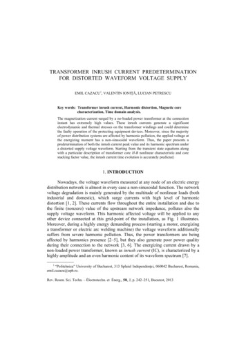
CIRED18th International Conference on Electricity DistributionTurin, 6-9 June 2005PRACTICAL ASPECTS OF TRANSFORMER INRUSH CURRENT CALCULATION USINGTWO SOFTWARE PACKAGESJ.G. SLOOTWEG*, C.P.J. JANSEN***Essent Netwerk B.V., P.O. Box 856, 5201 AW, ’s-Hertogenbosch**KEMA T&D Consulting, P.O. Box 9035, 6800 ET, ArnhemThe Netherlandshan.slootweg@essent.nl, kees.jansen@kema.comSUMMARYIn the paper, the simulation of the energizing of transformersand more specifically the calculation of inrush currents isdealt with. First, the physical origin of inrush currents isdiscussed. Then, two different transformers, namely a 20MVA 10.6/66 kV and a 160 MVA 66/220 kV transformer, areeach modelled in two different software packages, namelyATP and DIgSILENT Power Factory. The models aredescribed elaborately and the values of all relevant quantitiesare given.The models are used to simulate the energizing of the studiedtransformers from a generator and to investigate the impactof various quantities, such as remanent flux and switchinginstant. Finally, the simulation results are compared withmeasurements and it is observed that a satisfactory level ofcorrespondence has been achieved.INTRODUCTIONThe working principle of a transformer is based on thepresence of a magnetic flux, that couples the transformerwindings. The transformer’s iron core, that carries the fluxand is hence referred to as the magnetic circuit, isdimensioned for flux densities occurring during normaloperation. However, when the transformer is connected to thegrid after standstill, it must be magnetized, or energized, andflux densities much higher than the values during normaloperation may occur. These currents are referred to as inrushcurrents.In practice, inrush currents may pose problems for severalreasons [1, 2]: Protection schemes may act upon the amplitude and/orthe shape of the transformer inrush current, mistakenlyassuming that the observed currents are caused by somefault.When a transformer is energized from a weak grid or asingle generator, the voltage drop caused by the largeinrush currents may be such that undervoltage protectionschemes, if present, are triggered and again disconnectthe transformer that is just connected. Due to their non sinusoidal shape and the presence ofhigher harmonics, inrush currents can lead to resonanceovervoltages caused by the transformer non-linearimpedance and the capacitance of the line or cableconnected to it.In order to be able to prevent the occurrence of unintendedprotection system actions as well as damage due to resonanceCIRED2005Session No 1overvoltages, it is important to be able to simulate the switchon of a transformer accurately. This is, however, not verystraightforward, because it requires more advanced simulationapproaches than used in routine network analysis and becausemore elaborate data than the usual name plate data of thetransformer must be available.The investigation of transformer energizing and thecalculation of inrush currents form the subject of this paper. Itis organized as follows. First, the physical origin of inrushcurrents is shortly commented upon. Then, the topology andcharacteristics of the investigated system and its modelling inATP and DIgSILENT Power Factory are described. Finally,simulation results are presented and compared withmeasurements.ORIGIN OF INRUSH CURRENTSThe working principle of a transformer is governed byFaraday’s and Ampère’s laws [3-5]. Faraday’s law states thatinduced voltage is equal to the derivative of flux linkage, or,stated differently, that the coupled flux equals the integral ofthe applied voltage. Ampère’s law relates the flux linked by acoil to the current flowing through it.During normal operation, the transformer current and voltage,as well as the flux in the iron core, vary sinusoidally. Whenthe transformer is not loaded, i.e. one of the terminals is open,the phase shift between voltage on the one hand and flux andcurrent on the other, is approximately 90 degrees.Assume now that the transformer is idle and a voltage isapplied. When the presence of remanent magnetism isneglected and the connection happens at the instant at whichthe flux would equal zero during normal operation, i.e. at thevoltage’s maximum, this does not give rise to any exceptionalcurrent or flux. The flux is the integral of the applied voltageand is exactly equal to what it would be if this had not beenthe first period of the applied voltage.However, when the transformer is connected at the momentthat the voltage equals zero, the flux will reach twice itsnormal height when integrating the voltage. Had thetransformer already been connected, the integration wouldhave started from the negative maximum of the flux and endat the positive maximum of the flux. However, because this isthe first period of the voltage, the integration starts at zeroflux and the flux reaches twice the maximum value occurringduring normal operation.Because these high flux densities, the iron core is driven intosaturation. Therefore, the transformer starts to exhibit nonlinear behaviour. As a result, the current is no longer
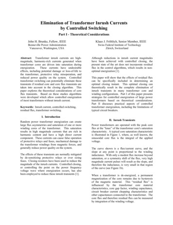
CIRED18th International Conference on Electricity DistributionMODELLINGTransformer 210.5 kV66.0 kV50 MVA10.5/70.5 kV160 MVA66.0/220.0 kV10.5 kVTable 1. Generator parametersValueQuantityGenerator Generator12Snom34.08350 MVAMVAUnom10.5 kV10.5 kVXdXd’Xd’’XqTransformer 1Transformer 30.10 p.u.*1.317mp.u.1.910 p.u.0.226 p.u.0.151 p.u.1.72 p.u.*Table 2. Transformer parametersQuantityTransformer 1, 2Snom20 MVAUHV66 kVULV10.6 kVUk14.7 %PCu87.6 kWP0, 100%10.3 kWI0, 100%0.77 mp.u.QuantityXq’Xq’’ValueGenerator Generator120.5 p.u.*0.5 p.u.*0.151 p.u.X0Td0’0.131p.u.*0.075 p.u.6,54 sTd0’’Tq0’Tq0’’0,04 s*0,50 s*0,15 s*0.018 s0.04 s*0,15 s*ValueTransformer 350 MVA70.5 kV10.5 kV11.0%116 kW31.3 kW2.3 mp.u.0.085 p.u.5.49 sTransformer 4160 MVA220 kV66 kV17.8 %459 kW71.4 kW1.04 mp.u.Transformer 434.0 MVA10.5 kV20.0 MVA10.6/66.0 kV220.0 kV GThe system studied in this paper consists of transformers andgenerators in island operation, as depicted in figure 1. Thegenerators have a rating of 34 MVA and 50 MVA at a voltageof 10.6 kV. The first generator is connected to a 66 kV busbarthrough a 26.5 MVA 10.6/66 kV transformers. It is driven bya gas turbine. The second generator is connected to the same66 kV busbar through a 50 MVA transformer.To investigate the inrush phenomenon and to validate thedeveloped models, firstly a second 26.5 MVA 10.6/66 kVtransformer and then a 160 MVA 66/220 kV transformer isconnected to this 66 kV busbar. In the first case, only onegenerator is in operation, whereas in the second case, both arein operation. The relevant parameters of the generator aregiven in table 1 and of the transformers in table 2. Theparameters not given in the generator documentation havebeen estimated and are marked with *. The one line diagramsof the systems are depicted in figure 1.0.10 p.u.*1.481mp.u.2.007 p.u.0.194 p.u.0.131 p.u.1.8 p.u.*20.0 MVA66.0/10.6 kV10.5 kV50 MVA10.5 kVSystem descriptionXlRl20.0 MVA10.6/66.0 kV G34.0 MVA10.5 kV Gapproximately proportional to the flux. Instead, much morecurrent is needed to increase the flux and the current caneasily reach much more than two times its maximum. Thislarge current is referred to as the inrush current. As statedearlier, inrush currents can lead to undesirable effects, such asthe triggering of protection devices and resonantovervoltages. The presence of remanent magnetism canincrease this effect, leading to even larger inrush currents.Turin, 6-9 June 2005Transformer 110.5 kV66.0 kVFigure 1. Investigated systemsATP ModelThe ATP model was developed using ATPDraw. Thegenerators were modelled as synchronous generators using themodel SM59 for which all relevant parameters are given intable 1. The transformers were modelled using the BCTRANdialog box. For those transformers connected directly to thegenerators, which were assumed to be already energized at thestart of the simulation, all nonlinearities were neglected. Incase of the transformer to be energized, the non-linearbehaviour was modelled using the pseudo-nonlinear hystereticinductor component Type 96 [6].The Φ-I characteristic of the nonlinear inductor provedcritical for matching the simulation results with themeasurements. However, it was unfortunately not availablefor the investigated transformers. Therefore, it was calculatedusing the supporting routine HYSDAT that comes with ATP.The values for Φ and I to be inserted in HYSDAT werederived using the “View ” function of the BCTRAN dialogbox. It was assumed that the positive saturation point, to beinserted in HYSDAT, lied at a voltage of 1.18 p.u., and thecorresponding no-load current was assumed to equal 10 timesthat at a voltage of 1.1 p.u. The assumption of a factor 10increase in the current was based on measurements taken fromone of the transformers, of which no-load measurements up toa voltage of 1.18 p.u. were available. These were used toextrapolate the value for the other transformers of which onlymeasurements up to a voltage of 1.1 p.u. were available.Power Factory ModelIn Power Factory the generators were modelled using thestandard synchronous machine model. The parameters for thegenerators are given in table 1. The transformer model inPower Factory used for the inrush simulations, is the twowinding transformer model shown in figure 2 [7]. The modelcontains the leakage reactances at the low and high voltageCIRED2005Session No 1
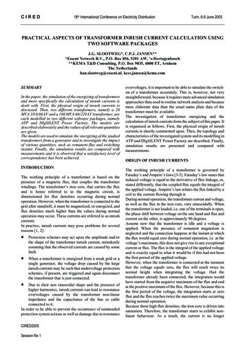
CIRED18th International Conference on Electricity Distributionside together with the winding resistance at low and highvoltage side. The model also shows the magnetizing reactanceXm and the ion losses resistance RFe.RprimXprimRsecXsecUsecUprimXMRFen1 : n2Figure 2. Transformer model in Power FactoryTo model the effect of inrush currents, the magnetizingreactance must be modelled as a function of the magnetizingcurrent. For that, the magnetic flux is given as a function ofthe magnetizing current in figure 3.ΦsaturatedΦkneeunsaturatediMFigure 3. Flux saturation model in Power FactoryThe unsaturated part of the curve is determined by thesimulation software from the no-load characteristics of thetransformer. The saturated part and also the knee flux, thenormal operating point of the transformer, is given by the Φ-Icharacteristic of the transformer. As already mentioned, thischaracteristic was not known for the transformers. For theknee flux a typical value 1.04 p.u. is used. For the ratiobetween the gradient of the saturated and unsaturated curve, atypical value of 500 is used. This value is tuned to get a bettermatch between simulated and measured curve of the inrushcurrent during the simulations. To model the remanentmagnetism in Power Factory, the value of the transformermagnetizing flux is set at a predefined value (between 0 and0.7 p.u.) at the start of a simulation.SIMULATION RESULTS AND MEASUREMENTSSimulation resultsNow, simulation results obtained with the models describedearlier are presented. Figures 4 and 5 show simulation resultsobtained with ATP. Figures 6 and 7 show simulation resultsobtained with Power Factory. In figures 4 and 6, the phasecurrents for the switching of the 26.5 MVA transformer(transformer 2) for two different instants are depicted. Infigures 5 and 7, the phase currents for the switching of the160 MVA transformer (transformer 4) for two differentinstants are depicted.CIRED2005Session No 1Turin, 6-9 June 2005As can be seen from the simulations, the shape and amplitudeof the inrush currents depend strongly on the instant ofconnection for both transformers. The cause of this is thephysical mechanism that causes the occurrence of the inrushcurrent, which makes them dependent on voltage atconnection instant as well as on remanent magnetism, asdescribed earlier.Further investigations with ATP on the impact of the presenceof remanent magnetism (which was created by first starting upthe simulation with the transformer connected and thendisconnecting and again reconnecting it) have shown thatwhen this was included, the simulation results varied evenmore widely [8]. However, in the rest of this paper, remanentmagnetism is not included in the ATP simulations in order toreduce the number of quantities to be varied.The simulations with Power Factory also showed that theinrush current is dependent on the instant of connection andon the assumed amount of remanent magnetism. In the PowerFactory model, the instant of connection and the amount ofremanent magnetism were tuned together with the value of theslope of the saturated flux (figure 3) in order to get the bestpossible agreement between the simulation results and themeasurements described in the next section. The tuningshowed that the amount of remanent magnetism and the valueof the saturated flux were up to a certain .030.05(f ile SW 20 2.pl4; x-v ar t) c:X0055C-X0051C0.07c:X0055A-X0051A0.09[s] .0150.0350.055(f ile SW 20 2.pl4; x-v ar t) c:X0055C-X0051C0.075c:X0055A-X0051A0.095[s] 0.115c:X0055B-X0051BFigure 4. Simulation of the connection of transformer 2 with ATP
CIRED18th International Conference on Electricity DistributionTurin, 6-9 June .00-1000-1500-2000.00-20000.0080.0280.048(f ile SW 160 2.pl4; x-v ar t) c:X0024B-X0001B0.068c:X0024C-X0001C0.088[s] 0.10815000.0025.0050.0075.00[ms]100.38-1T261: Phase Current A/LV-Side in A38-1T261: Phase Current B/LV-Side in A38-1T261: Phase Current C/LV-Side in 048(f ile SW 160 2.pl4; x-v ar t) c:X0024B-X0001B0.068c:X0024C-X0001C0.088[s] 0.108c:X0024A-X0001AFigure 5. Simulation of the connection of transformer 4 with ATP0.0025.0050.0075.00[ms]100.38-1T261: Phase Current A/LV-Side in A38-1T261: Phase Current B/LV-Side in A38-1T261: Phase Current C/LV-Side in AFigure 7. Simulation of the connectio
PRACTICAL ASPECTS OF TRANSFORMER INRUSH CURRENT CALCULATION USING TWO SOFTWARE PACKAGES J.G. SLOOTWEG*, C.P.J. JANSEN** *Essent Netwerk B.V., P.O. Box 856, 5201 AW, ’s-Hertogenbosch **KEMA T&D Consulting, P.O. Box 9035, 6800 ET, Arnhem The Netherlands han.slootweg@essent.nl, kees.jansen@kema.com SUMMARY In the paper, the simulation of the energizing of transformers