Transcription
TRANSFORMER INRUSH CURRENT PREDETERMINATIONFOR DISTORTED WAVEFORM VOLTAGE SUPPLYEMIL CAZACU1, VALENTIN IONIŢĂ, LUCIAN PETRESCUKey words: Transformer inrush current, Harmonic distortion, Magnetic corecharacterization, Time domain analysis.The magnetization current surged by a no-loaded power transformer at the connectioninstant has extremely high values. These inrush currents generate a significantelectrodynamic and thermal stresses on the transformer windings and could determinethe faulty operation of the protecting equipment devices. Moreover, since the majorityof power distribution systems are affected by harmonic pollution, the applied voltage atthe energizing moment has a non-sinusoidal waveform. Thus, the paper presents apredetermination of both the inrush current peak value and its harmonic spectrum undera distorted supply voltage waveform. Starting from the transient state equations alongwith a particular description of transformer core H-B nonlinear characteristic and corestacking factor value, the inrush current time evolution is accurately predicted.1. INTRODUCTIONNowadays, the voltage waveform measured at any node of an electric energydistribution network is almost in every case a non-sinusoidal function. The networkvoltage degradation is mainly generated by the multitude of nonlinear loads (bothindustrial and domestic), which surge currents with high level of harmonicdistortion [1, 2]. These currents flow throughout the entire installation and due tothe finite (nonzero) value of the upstream network impedance, pollutes also thesupply voltage waveform. This harmonic affected voltage will be applied to anyother device connected at this grid-point of the installation, as Fig. 1 illustrates.Moreover, during a highly energy demanding process (starting a motor, energizinga transformer or electric arc welding machine) the voltage waveform additionallysuffers from severe harmonic pollution. Thus, the power transformers are beingaffected by harmonics presence [2–5], but they also generate poor power qualityduring their connection to the network [3, 6]. The energizing current drawn by anon-loaded power transformer, known as inrush current (IC), is characterized by ahighly amplitude and an even harmonic content of its waveform spectrum [7].1“Politehnica” University of Bucharest, 313 Splaiul Independenţei, 060042 Bucharest, Romania,emil.cazacu@upb.ro.Rev. Roum. Sci. Techn. – Électrotechn. et Énerg., 58, 3, p. 242–251, Bucarest, 2013
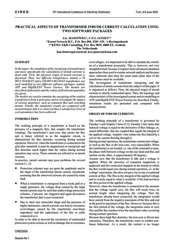
2Transformer inrush current under distorted supply voltage243Network power supplyEDistorted currentwaveformDistorted voltagewaveformUpstreamnetworkimpedance0MLinear loadsHarmonic generators( Nonlinear loads)DomesticloadsInvestigated EnergizedTransformerFig. 1 – The network voltage degradation process and the transformer connection networkpoint.As a result of its great importance in power systems, the inrush currentproblem has been studied in numerous papers [8–14], but only recently theharmonic content of the applied voltage was also considered [15–19]. Complexityof the problem lies in the dynamic of waveform spectrum and the mutualinfluences between the active network devices during the transient process [19].This paper is going to investigate the main characteristics of the IC (peak value,first cycle harmonic spectrum and duration) for a single-phase power transformer(used in low-voltage installations) under a real (distorted) supply voltage.Additionally, a case study quantitatively illustrates the theoretical approach. Due tothe low rated power range of the investigated energized transformers, it is assumedthat the network voltage waveform is preserved during the transient process.2. INRUSH CURRENT EVALUATIONThe main purpose of the single-phase power transformers used inlow-voltage installations is to provide electric energy (at different parameters) for alarge variety of loads. Additionally, in certain applications, they may also performthe electrical isolation between the power supply and the electric appliances.During their operating time, transformers experience numerous commutationsprocesses. Consequently, the predetermination of the IC features is required inorder to properly consider its instantaneous effects both over the installation andthe transformer (abnormal operation of the protective devices, overloading thenearby equipments and other power quality issues).
244Emil Cazacu, Valentin Ioniţă, Lucian Petrescu3For a better illustration of the IC computation suggested procedure, our studyfocuses on a particular class of power transformers, commonly found in lowvoltage applications. More specifically, UI magnetic core shape devices (with arated power up to 25 kVA) having the geometrical data indicated in Appendix 1.The inrush current time evolution i(t) immediately after the transformerswitching could be derive from the instantaneous electric circuit equations alongwith Ampère's circuital law applied on the magnetic core device. Thus, taking theprimary winding with resistance R1 and turns number N1, and the mean magneticpath length lm of a cross section core area Ac, the inrush current i(t) and magneticinduction B(t) time dependency can be expressed:d B (t ) , u(t ) R1i (t ) N1 Acdt N1i (t ) H (t )lm , H f ( B (t )),(1)where u(t) is the supplied non-sinusoidal voltage and H(t) is the core magnetic fieldstrength.In order to solve the above equation system, a representation of the magneticcore nonlinear characteristic in terms of H-B relationship is imposed. Variousapproximation functions can be chosen. Since the accuracy description of the coreheavy saturation area is important for the IC generation phenomenon, the Brauerexpression was here selected [20]:H mB nB exp( pB 2 ),(2)where m, n and p constants are accordingly determined for any type of corelamination steel by a simple fitting procedure (constraining the expression to passthrough at least three of the electrical steel given data points).Finally, the nonlinear differential algebraic equations system described by (1)is numerically solved using Rosenbrock method [21]. The magnetic core fluxdensity before the energizing process Br0 represents the necessary initial valueparameter, which is always taken as the remnant magnetization. Thus, the worstcase scenario is considered.Many transformers’ protecting equipment devices discriminate the IC fromdifferent internal fault currents (e. g. short circuits) by investigating the transientcurrent harmonic spectrum of the first cycle (during a period time of thefundamental voltage supply waveform T 2π/ω). This principle is also known asthe second harmonic restraint procedure [7, 22, 23]. In that respect, a numericalharmonic analyze over the first cycle of IC waveform, which relies on the Fourierseries [9, 11, 24, 25], is also accomplished. Hence, the spectrum of IC first cycle isaccordingly evaluated [1–3] along with each harmonic percentage level (Hh) withrespect to the fundamental and its total harmonic distortion (THDI):
4Transformer inrush current under distorted supply voltagei (t ) m [Ah245cos(hωt ) Bh sin(hωt )],h 0TA0 1i (t ) d t ,T 0 TAh T22i (t ) cos(hωt ) d t , Bh i (t ) sin(hωt ) d t ,T 0T 0 mI h Ah2 Bh2 , H h [%] Ih 100, THD I I1 Ih 2I1(3)2h 100.In order to quantitatively describe the level of supply voltage harmonicpollution, the total harmonic distortion THDU indicator was also adopted (derivedfrom voltage signal Fourier series decomposition):nTHDU Uk 2U12k 100, u(t ) n Uk2 sin( kωt ),(4)k 1with k the harmonic order of effective value Uk, and angular frequency kω.The IC evaluation described above can be easily implemented in any generalpurpose computation environment, once all the required data (for both transformerand applied voltage) are available. The applied distorted voltage is to beinvestigated before starting the energizing process. That can be achieved by using ahigh performance measuring and monitoring device, such a modern power qualityanalyzer, which is able to provide a complete harmonics signal profile up to the 51stharmonic. This valuable information may lead to accurate IC predeterminationparameters. In the following section a case study is going to illustrate the flexibilityof the suggested IC computation procedure. Supplementary, the harmonic voltagespectrum influence of the IC characteristics is revealed by performing specificquantitative parametric estimations.3. NUMERICAL APPROACH – CASE STUDIESA low-voltage single phase power transformer of 2 kVA rated power, whosecomplete data are indicated in Appendix 1, is to be energized at a certain grid pointof an electric installation. At this specific network node numerous nonlinear loadsare already on duty (adjustable speed drives, switching power supplies, dischargedlamps and other) as depicted in Fig. 1. The supply voltage characteristics wereinvestigated with a class A power quality analyzer [26].
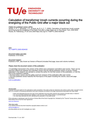
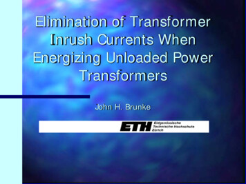
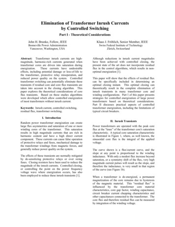
246Emil Cazacu, Valentin Ioniţă, Lucian PetrescuFig. 2 – The grid node voltage waveformsof the three-phase supply voltages.5Fig. 3 – The grid node voltage harmonic contentof the three-phase supply voltages.Hence, the captured images of voltages waveform and its harmonic content(with percentage contribution of each component related to the fundamental) arepresented in Fig. 2 and Fig. 3, respectively. One can notice that the total harmonicdistortion of the three voltages waveforms reaches THDU 6.4 %. The transformercore magnetic material is a non-oriented grain silicon steel M 27 and correspondsto a stacking factor of kST 0.94. The magnetic material characterization isdescribed by the magnetization curve as a finite number of measured pair of points.Fig. 4 – Transformer core magnetization curve(marker) and the adopted Brauer functions (curve).Fig. 5 – Transformer inrush current computedvariation during a five period time.
6Transformer inrush current under distorted supply voltage247Figure 4 represents this magnetization curve along with corresponding Brauerapproximation of the B-H relationship. Applying the IC procedure evaluationpresented in the previous section, the transformer IC variation immediately afterthe transformer switching process is obtained. Figure 5 depicts IC time evolutionduring 100 ms. The amplitude reaches 513.78 A at 7.62 ms after the commutationoccurred. One can notice that it decays very rapidly (only after a few cycles) andultimately its steady state value, also called magnetization current, is practicallyaround one percent from the transformer rated current (for this particular deviceonly 0.11 A). The harmonic investigation performed over the first cycle of ICwaveform, indicates a significant percentage level with respect to the fundamentalof zero (DC) and second harmonic. Correspondingly, Fig 6 presents the spectrumhistogram of IC first cycle.Aiming to also estimate the harmonic voltage distortion level influence overthe IC characteristics, various quantitative parametric evaluations have beenconsidered. Thus, Fig. 7 represents the IC amplitude as a function of the voltagetotal harmonic distortion (THDU).The amplitude variation of zero (H0) and second (H2) harmonic component ofthe first cycle IC waveform, defined according to the last expression of (3), isdepicted in Fig. 8. The total harmonic distortion (THDI) of the IC first cyclealteration due to the voltage distortion is presented in Fig. 9.Fig. 6 – IC first cycle computed harmonicspectrum histogram.Fig. 7 – Computed IC amplitude variationwith the voltage total harmonic distortion.
248Emil Cazacu, Valentin Ioniţă, Lucian PetrescuFig. 8 – The main IC first cycle harmoniccomponents computed variation with THDU.7Fig. 9 – The IC first cycle total harmonicdistortion computed variation with THDU.4. CONCLUSIONSAn analytical procedure that predicts the IC parameters of a single phasepower transformer under a distorted voltage condition is presented. The evaluationmethod is based on the solution of the nonlinear differential algebraic equationssystem derived from the transformer’s circuit model and its magnetic corecharacterization. Since nowadays the voltage harmonic content can be accuratelymeasured, the voltage distortion is accordingly modeled by Fourier series. Thevariations of the IC features corresponding to the level of voltage harmonicpollution (THDU) are investigated. Thus, the IC amplitude and its first cyclewaveform zero harmonic component are increasing along with the voltagedegradation, while IC distortion (THDI) and the second harmonic amplitudediminish. These parameters are particularly important because they generate thethermal and electrodynamical stresses experienced by transformer during thecommutation process (IC amplitude) and also lead to the proper selection of theprotection equipment or method (e.g. second harmonic attendance discriminationprocedure between IC and short circuit). The level of voltage distortion whichcould be measured at different grid nodes of common low-voltage electricinstallations (THDU 20%), do not generate critical values for the transformer ICparameters. Nevertheless, the constant demand for energy efficiency, operatingflexibility and high performance levels for the electric appliances require the largescale usage of power electronic equipment. Consequently, the voltage distortion isexpected to constantly increase.
8Transformer inrush current under distorted supply voltage249The proposed IC computing procedure could be further developed in terms ofits preciseness. For instance, since the THDU is a non-unique quantitativeparameter of voltage harmonic pollution (the same value can result from differentvoltage waveforms), other (qualitative) distortion indicators are to be found inorder to better describe the non-sinusoidal influence over the IC features.Additionally, a better core magnetic material description (e. g. taking into accountthe laminations hysteresis loop instead of their magnetization curve) could alsolead to a more accu
Thus, the power transformers are being affected by harmonics presence [2–5], but they also generate poor power quality during their connection to the network [3, 6]. The energizing current drawn by a non-loaded power transformer, known as inrush current (IC), is characterized by a highly amplitude and an even harmonic content of its waveform spectrum [7]. 1 “Politehnica” University of .