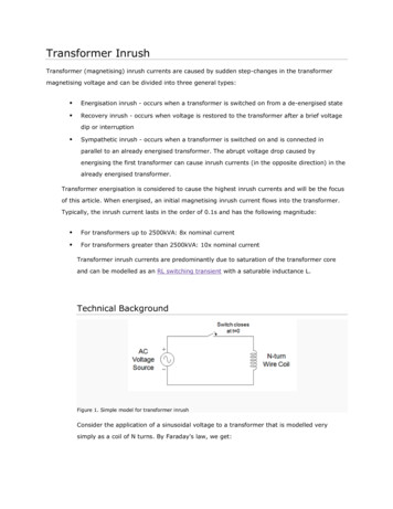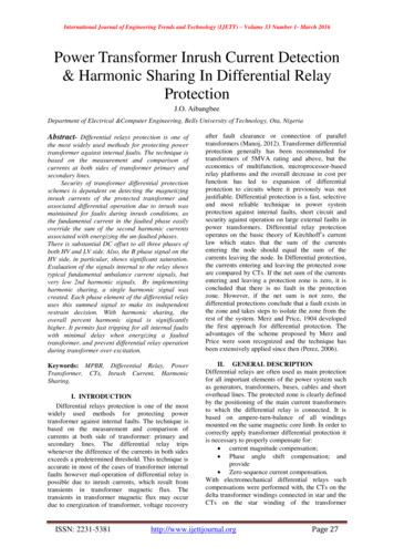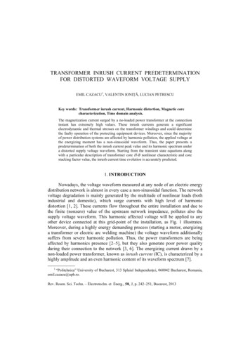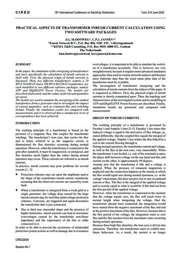
Transcription
Transformer Inrush andVoltage Sag – P28 StudiesAugust 2017
Introduction This presentation is intended to give a simple overview of transformer inrush andenergisation and why it is important to network operators (DNOs). When a transformer is energised it can draw many times its rated power which can causea significant voltage dip on the distribution network causing problems for othercustomers. In the UK, the standard that covers the allowable voltage dips is ENA P28. Inrush studies are usually required by the DNO for generating sites protected by a G59relay, as the G59 relay can lead to multiple trips and re-energisations a year. Location of the G59 relay is a key factor!www.sp-eng.co.uk
Transformer Inrush - Overview When transformers are switched on they become magnetised, this process can draw alarge amount of power. The transformers load does not matter – even unloaded transformers cause this effect. Small distribution transformers ( 2.5MVA) usually have an inrush current of 8-10x theirrated power, while larger power transformers tend to have an inrush current of 5-8x theirrated power. Inrush can last from a few cycles to several seconds. Transformer inrush is a non-linear electromagnetic transient phenomena and difficult toanalyse with standard power system analysis software.www.sp-eng.co.uk
Transformer Inrush – Overview Continued The magnitude of the inrush current and network voltage dip, depends on: Transformer design, Remnant flux in the transformer, Switching angle, Network short circuit level. It is difficult to mitigate inrush currents - if the energisation causes an excessive voltagedip then it is necessary to consider pre-magnetization systems or Pre-Insertion Resistors(PIRs). These can be expensive and difficult to obtain if their requirement is identified at the lastminute.www.sp-eng.co.uk
Transformer Magnetization – Simple Theory A transformer behaviour is non-linear andis characterised by a B-H Curve When a transformer is first energised thetransformer acts like a simple inductorand the core must be magnetized. This magnetization current depends onthe properties of the transformer and thepoint on the cycle at which thetransformer is energised. The full B-H hysteresis curve is notnecessary for most inrush studies andonly the top quadrant is used.www.sp-eng.co.uk
Transformer Magnetization – Simple Theory The B-H curve can be defined as anequivalent Flux-Current curve. An equivalent curve is created using thetransformer open circuit test data and the‘air core reactance’. The initial slope is defined by thetransformer materials and construction. Air core reactance is the final slope of theFlux-current curve and represents thetransformer in saturation (i.e. inrush) Air core reactance is normally not knownand has to be estimated based on typicalparameters or the core/yoke topography.www.sp-eng.co.uk
Transformer Inrush – Simple Theory When a transformer is first energised itenters the saturated region. This causesthe large amount of current to flow. The deeper into the saturation region, thegreater the current drawn. Energisation at a zero voltage crossingproduces the most current, as the fluxlags the voltage by ¼ cycle (π/2) i.e. peakflux occurs at a zero voltage. If the transformer contains remnant fluxthis can push the flux higher into thesaturation region.www.sp-eng.co.uk
Network Voltage Depression When a large inrush current flows this results in a voltage depression. This is of concern to a DNO, who must maintain acceptable power quality on thenetwork. The voltage dip limits are defined in ENA P28, and the distribution code: 1% for frequent energisations 3% for energisations more than 10 minutes apart 10% for transient events once per year (distribution code) A renewable site with a G59 relay typically can experience 1 trip / quarter. The magnitude of the voltage depression depends on a combination of thetransformer inrush current (see earlier slides) and the network strength.www.sp-eng.co.uk
DNO Network Strength The DNO’s network strength is defined by its fault level (either in kA or MVA). Network fault levels usually have a maximum and a minimum value, depending on thesystem configuration. Statistically is it very unlikely that a transformer will be energised at a voltage zero, whilethe system is at the minimum fault level, so it is usually best to use the maximum faultlevel. (This is actually recommended in ENA P28) It is important to understand the difference between the Point of Connection (POC) andthe Point of Common Coupling (PCC). The PCC is where other customers connect on the network, so it is the important one!www.sp-eng.co.uk
Putting It All Together Determining the system response to a transformer energisation event is not simplecalculation – use of packages like EMTP-ATP or PSCAD/EMTDC are needed. A transformer inrush current is defined by several parameters: Transformer construction and materials, Point on the voltage wave that the transformer is energised, Remnant flux in the transformer. The voltage dip experienced by the DNO will depend on: The transformer inrush current, The network strength (fault level), The POC and PCC relationship.www.sp-eng.co.uk
Computer Simulation - PSCADwww.sp-eng.co.uk
Computer Simulation – EMTP-ATPwww.sp-eng.co.uk
Summary Meeting the 3% voltage dip limits in ENA P28 can be challenging for largetransformers on a rural network – studies should not be thought of as a simpleformality. The voltage dip depends on the transformer design, residual flux, switchingangle and DNO network strength. If the voltage dip is too large the DNO can insist on pre-insertion resistors, or apre-magnetization system. These can be expensive and have a long lead time –not ideal if there is an energisation date coming up. How can we help?www.sp-eng.co.uk
What Next? All questions welcome! SPE’s website has a lot of further information, or contacts us to discuss yourissue. www.sp-eng.co.uk info@sp-eng.co.uk How can SPE help you with your design?www.sp-eng.co.uk
The transformers load does not matter –even unloaded transformers cause this effect. Small distribution transformers ( 2.5MVA) usually have an inrush current of 8-10x their rated power, while larger power transformers tend to have an inrush current of 5-8x their rated power. Inrush can last from a few cycles to several seconds.
