Transcription
Dr. Gilles BenoitMassachusetts Institute of Technology, Cambridge, MADr. Richard SunAngstrom Sun Technologies Inc., Acton, MA
Principle Instrumentation Modeling General Applications Summary
On Spectroscopic Ellipsometry
Light waves are electromagnetic in nature and require four basicfield vectors to completely describe them.The electric-field strength: E The electric-displacement density: D The magnetic-field strength: H and The magnetic-flux density: B Of these four vectors, the electric-field strength is chosen todescribe the polarization state of light waves. It is because the forceexerted on the electrons by E is much greater than by the magneticfiled of the wave when light interacts with matter. Once thepolarization of electric-field vector has been determined, the otherthree vectors can be also determined based on Maxwell’s fieldequations and the associated constitutive material relations.
For simplification, we consider a linearly polarized plane wave which propagatesalong the positive z direction and vibrates in the x-plane. The electric field of thewave can be written as: zN E x E0 exp i t c 22 E Ex E x2xc 4 22 t z twhere Ex is the x-component of the electric-field strength; is the dielectric constant; is the conductivity. ( 2 ) is the angular frequency, E0 is the maximal value of the electric field strength. N is the complex index of refraction z (n ik ) E x E0 exp i t c N n ik kE x E0 exp cDamped Term zn z exp i t c Undamped Term
Rolf E. Hummel: Electronic Properties of Materials, Springer-Verlag, 2nd Edition, 1997
R.M.A Azzam & N.M. Bashara: Ellipsometry and Polarized Light, Elsevier Sci., New York, 1999
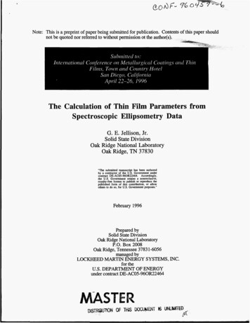
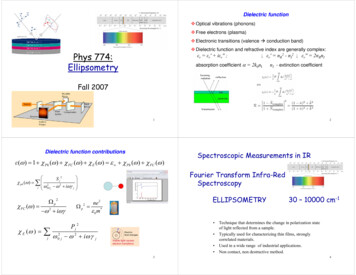
---- The extremity of its electric field vector describes an ellipse (a) Elliptically polarized light; (b) decomposition of elliptically polarized light into two(b) mutually perpendicular plane polarized waves P and S with a phase difference, Delta;R.W. Pohl, Optik und Atomphysik, Springer-Verlag, Berlin, 1958
PaA b0 rpYrsSSin2 Sin2 Sin Tan2 Tan2 Cos (1) Azimuth , which is the angle between the major axis of the ellipse and the positivedirection of the P. It defines the orientation of the ellipse ( -90o 90o ).(2) Ellipticity e, which is the ratio of the length of the semi-minor axis and that of itssemi-major axis. e a/b Tan( )(3) Amplitude A, which is a measure of the strength of elliptical vibration. Its square isproportional to the energy density of the wave. A (a2 b2)1/2(4) Handedness, which is used to describe wave propagation sense. Right handed –clockwise; Left handed – counter-clockwise when looking into the beam.
Rolf E. Hummel: Electronic Properties of Materials, Springer-Verlag, 2nd Edition, 1997
PSource: Newport
2 2 Sin2 Sin2 Sin Tan2 Tan2 Cos
R.M.A Azzam & N.M. Bashara: Ellipsometry and Polarized Light, Elsevier Sci., NewYork, 1999
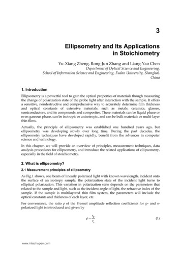
EirpEPfErrsESAmbient (no, ko)Film 1 (n1 k1 d1)Film 2 (n2 k2 d2)Film i (ni ki di)Substrate (ns ks)PRj r S Tan e f (ni , k i , d i L)R
Instrumentation
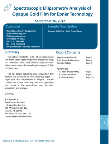
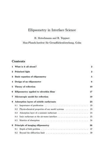
CCDLightSourceGoniometerP CSpectrometerAPMTTFProbe SEMonochromator
GoniometerP CTFProbe SEA
SingleWavelengthEllipsometer(SWE)VUV / PUVVisVis NIRIR-SE
Speed(Signal Processing)In-situMultiple Channel (CCD)(Real Time)Discrete Wavelengths (Lasers)Ex-situScanning Wavelength SE(Integrated)Null SWER&D DesktopSemi automaticFully AutomaticVUV- DUV – VIS – NIR - IROff Line (Lab)In Line (Fab.)Automation(Sample Handling)SWE - SE (ApplicationOriented)
On Spectroscopic EllipsometryModeling
RPr S Tan e j f (ni , k i , d i L)RPhysical ModelEstimated sample structure- Film Stack and structure- Material n, k, dispersion- Composition Fraction of MixtureMeasured DataTanY Cos Measurement Calculation ?YesTi , ni , kiNo
2. Snell’s Law: aAmbient(air)aSubstrate cc N a Sin a N c Sin c3. Ellipsometry Equation1. Fresnel Reflection Coefficients: N cCos a N aCos cPrac N cCos a N aCos c NCos NSaac Cos crac N aCos a N cCos cracPr Srac4. Optical Constants2 1 r Tan 2 aN Sin a 1 1 r
- Multi reflections between interface a/b and interface b/c- From the Fresnel coefficients at the interface a/b and b/c, thetotal reflection coefficients can be calculated as:IPP j 2 r rPabbc eR P P j 2 1 rab rbc eS j 2 bcS S j 2 ab bcr r eR 1 r r eSabSd 2 ( )(nb jkb )Cos b R aad bbc cTRPr S Tan e j R
I 00/1R Ambient: 0 Layer 11/2 Layer 22/3 (i-1)/idi iLayer ii/(i 1)Layer m sSubstrate: sM films in structurePlanar assumedIsotropic andhomogenousIncident angle known Facts: M layers one substrate M 1 interfaces Unknowns: Each layer thickness (m) Optical constants (n & k, 2m) Ellipsometer Data: One set of Y & at each wavelength
1. Fresnel Reflection Coefficients: N i Cos i 1 N i 1Cos iPr(i 1) / i N i Cos i 1 N i 1Cos i N Cos i 1 N i Cos ir(Si 1) / i i 1 N i 1Cos i 1 N i Cos i4. Phase Factordi i 2 ( ) N i Cos i I2. Fresnel Transmission Coefficients: 2NPi 1Cos i 1t(i 1) / i N i Cos i 1 N i 1Cos i 2NSi Cos it(i 1) / i N i 1Cos i 1 N i Cos i3. Snell’s Law N i Sin i N i 1Sin i 1R i-1ai-1adi ibibi 1c i 1cT
Interface Matrix I (a &b)I ab 1 / t ab rab / t abrab / t ab 1 (1 / t ab ) 1 / t ab rabLayer Matrixrab 1 S I 01 L1 I 12 L2 I 23 L3 I 34 L4 I ( m 1) m Lm I msS 21R S111T S11 e j L 0 S11 S 210 j e S12 S 22 RPr S Tan e j f (ni , k i , d i L)R
ModelEstimated sample structure- Film Stack and structure- Material n, k, dispersion- Composition Fraction of MixtureMeasured DataTanY Cos 2 ?NoYes ?Ti , ni , kin1ii 2 [(TanYTheory TanYExp) 2 (Cos iTheory Cos iExp ) 2 ] 2n m 1 i 1
Front FaceNK Table:- Homogeneous- GradedThicknessLayer 2NK Profile:- Linear- Gaussian- Exponential- morePropertiesPhysics Model:- Bruggeman- Maxwell-GarnettBack FaceDispersionSubstrateInterfaceLayer mNK & Disp.Dispersion:NK TableLayer StackLayer 1- Isotropic- Anisotropic- Cauchy- Sellmeier- Exponential- Tauc-Lorentz- Drude- More
Front FaceLayer StackLayer 1Layer 2Layer mSubstrateBack Facea. Thicknessb. VolumeFraction of 2ndor 3rd MaterialsNK Table:- Homogeneous- GradedNK Profile:Properties(Mixture of2 or 3Materials)- Linear- Gaussian- Exponential- morePhysics Model:- Bruggeman- Maxwell-Garnett
Front Facea. Thicknessb. Concentrationof 2nd ElementLayer StackLayer 1Layer 2Layer mSubstrateBack FaceProperties(Alloy)NK Table:- Relaxed- Strained
Front FaceLayer StackLayer 1Layer 2Layer mSubstrateBack Facea. Thicknessb. VolumeFraction ofLower MaterialNK Table:- Homogeneous- GradedNK Profile:Properties(Mixture ofAbove andBeneathMaterial)- Linear- Gaussian- Exponential- morePhysics Model:- Bruggeman- Maxwell-Garnett
Front FaceLayer StackLayer 1Layer 2a. Thicknessb. VolumeFraction ofLower MaterialSubstrateBack Face- Homogeneous- GradedNK Profile:Properties(Mixture ofAir and TopMaterial)Layer mNK Table:- Linear- Gaussian- Exponential- morePhysics Model:- Bruggeman- Maxwell-Garnett
Microscopic PropertyPolarizability: 4 1N 3 2Macroscopic PropertyDielectric Response: Clausius-Massotti Equation(N is the density of polarizable units) a 1 b 1 1 fa fb 2 a 2 b 2Lorentz-Lorentz Equation(f’s are volume fractions for each polarizable components a & b)
h a h b h fa fb 2 h a 2 h b 2 ha and b are in a host with dielectric constant of h(Philos. Trans. R. Soc., London, 205,1906, 237) h h a b
A.G. Bruggeman, Ann. Phys. (Liepzig) 24, 636 (1935)The Bruggeman model is also called Effective Medium Approximation (EMA).In this model, the two media play exactly the same role. The effective dielectricfunction of the mixture is given by the second order equation : h a b 0 fa fb a 2 b 2 a bThe two materials plays the same role but they are in interaction. Each type of inclusion is in interactionwith the medium (it is supposed nevertheless spherical, depolarization coefficient equal to 1/3 ).
R.W.Collins, et al., Thin Solid Films,313-314,1998, pp18-32
Source: K. Vedam, Thin Solid Film14 (1998) pp. 1-9
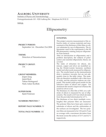
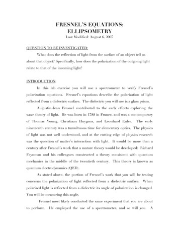
SE ModelThickness (nm) n@1550nm13.51.7211424.422.236366.712.2825Si SubstrateSEM Photo
DispersionUV ContributionIR DrudeDispersion:- Isotropic- Anisotropic- Cauchy- Sellmeier- Exponential- Tauc-Lorentz- Drude- .Absorption Band 1Absorption Band 2Absorption Band j- Lorentz- Gaussian- .Anisotropic:- Uniaxial X- Uniaxial Y- Uniaxial Z- Biaxial XYZ
UV ContributionDispersion- Cauchy NK- Cauchy r/ i- Sellmeier- Exponentialn A B / 2 C / 4k D E / 2 F / 4 r A B / 2 C / 4 i D / E / 3 F / 5 r 1 ( A2 1) 2 /( 2 B) i C / D / 2 E / 3 r A B 2 C ( D ( E F / 2 ) / 2 ) / 2 ) 2 i 0 i( E ) -Tauc-LorentzAE0C ( E E g ) 2(( E 2 E0 ) 2 C 2 E 2 ) E i( E ) 0- morefor E Egfor E Eg
r P (1 / Lo )2 2 /(1 ((1 / ) )2 ) i (1 / )(1 / Lo ) /(1 ((1 / ) ) )Dispersion232IR DrudeNote: P is the polarization, 1/ the mean free passand 1/Lo the inverse of the plasma wavelength.
- Lorentz r A 2 ( 2 L0 2 ) / ( 2 L0 2 ) 2 2 2 Dispersion i A 3 / ( 2 L0 2 ) 2 2 2 Note: A is the amplitude , Lo is the centralwavelength and is the width of the bandor peak.Absorption Band 1Absorption Band 2 r A imag ( DoubleW( z )) i A real( DoubleW( z))DoubleW( z) (exp( z 2 ) erfc( iz)Absorption Band jz (1 / L0 1 / ) / - Gaussian
with Spectroscopic Ellipsometry
Optical constants or dielectric constants for bulkmaterials Optical constants and thickness for films Surface, Interface and Composites Alloy concentration determination Real time monitoring for growth or etchingkinetics study Band gaps Porosity Other properties derived from optical /dielectricconstants
Materials: Metals Polymers Ceramics and Glasses Semiconductors and its Compounds Composites Application Fields Semiconductor Industry: Photoresist, Gate dielectrics, Semiconductors and their alloysor compounds such as, SiGe, InGaAs, AlInGaAs Photonics Optical coatings Semiconductor compounds Functional films in Optical MEMS Data Storage Diamond-like carbon (DLC) Magnetic films Flat Panel Display (FPD) Thin film transistors (TFT) stack Conductive oxide: Indium Tin Oxide (ITO) Solar Cell Industry
SiNxMembraneTop MirrorAlSubstrateActive QW RegionFiberBottom Mirror
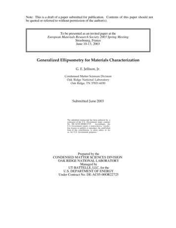
SESiOAnalyzer2Polarizer23.1 0.3SEnmTa2O5180.3 0.2 nmSiO2224.3 0.2 nmTa2O5169.4 0.2 nmBK7 Glass SubstrateSicr
Ellipsometry is a technique through monitoringthe polarization state changes. It offers nondestructive way to accurately determinefilm thickness and optical constantsMany types of ellipsometers are available in themarket. The selection and use of ellipsometer arehighly application-oriented.SE has advantages over many other techniques.The ellipsometry is the MODEL based technique.It is not direct readout type instrument.Therefore: It is critical to use the right model to get right results
Ellipsometry has many advantages over other techniques:1. More comprehensive than any other tools: Optical,electrical, physical (or structural) and chemical(composition, bonding). All these information may beobtained from only one measurement.2. Nondestructive compared with SIMS for composition3. Non-contact compared with four-point probe forconductivity4. Non-contact and no pattern needed compared withstylus profilometer for thickness5. No vacuum requirement compared with all e-beam orion-beam based instrument
6. Ellipsometry is an absolute technique (no need ofreference or standards)7. Ellipsometry gives twice more information (both phaseand amplitude ratio) than reflectometry (only intensity).In addition, as ellipsometer measures the polarisationstate and not the intensity, it is less sensitive to lightintensity fluctuations.8. The phase information from ellipsometry is verysensitive to surface layers. Therefore, it is the bestnon-destructive technique for thin film characterisation.
www.angstec.comInfo@angstec.comPhone: (978) 263-6678Fax: (978) 263-6675
R.M.A Azzam & N.M. Bashara: Ellipsometry and Polarized Light, Elsevier Sci., New York, 1999 ---- The extremity of its electric field vector describes an ellipse (a) Elliptically polarized light; (b) decomposition of elliptically polarized light into two (b) mutually perpendicular plane polarized