Transcription
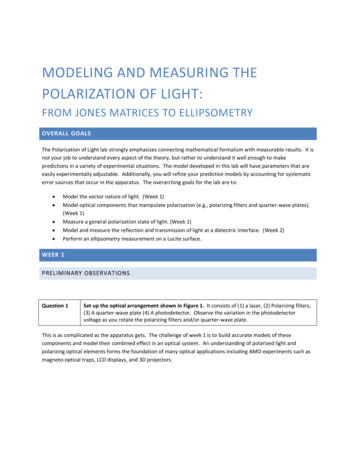
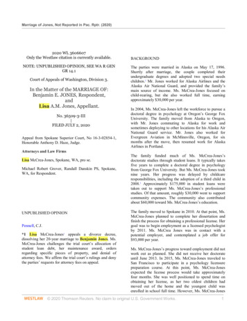
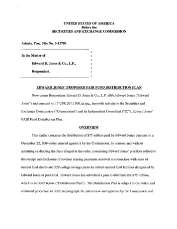
Polarization of Electromagnetic Wave General consideration of polarization Jones Formalism How Polarizers workPhys 774:Polarization of Light Muller matrices Stokes parameters Poincare sphere Ex GGGG E (r , t ) E0 exp[i (kr ωt )] E y E z Fall 20071Polarization of Electromagnetic WaveWhere is the polarization information hidden ?Polarization of Electromagnetic Wave Jones Formalism Jones Formalism / Lecture QZ Ex GGGG E (r , t ) E0 exp[i (kr ωt )] E y E z Elliptically polarized light2GG Eexp[i(kr ωt )] Ex 0xG G E y E0 y exp[i ( kr ωt )]G G E z 0 (for k z ) 1 1 1 0.924 0 i 1.848 0.383 i 2 rx eiδ x G ;( rx2 ry2 1)E Jones E0 iδ y ry e 3 For Polarized lightstate of polarizationis represented by 2x1matrix of complexamplitudes:G E0 x E Jones E0 y 4
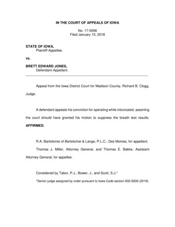
Jones representation for PolarizationPolarization of Electromagnetic Wave Jones Formalism for polarization; E-matrices General consideration of polarization Ex GGGG E (r , t ) E0 exp[i (kr ωt )] E y E z G GD ε 0ε E ε xx ε xy ε xz Ex Dx Dεεεε Ey yyxyyyz0 D z ε zx ε zy ε zz Ez 6 independentcomponentsε (ω ) 1 χ (ω )G1 1 E Jones E0 2 i Light polarized along xIn general situation: ε xx ε xy ε xz ε xx 0 0 ε ε yx ε yy ε yz 0 ε yy 0 ε ε ε 0 0 ε zz zx zy zz In isotropic media: ε xx ε xy ε xz ε 0 0 ε ε yx ε yy ε yz 0 ε 0 ε ε ε ε 0 0 ε zx zy zz 5Jones representation for PolarizationG E 1 Ex Jones 0 x E0 x 0 0 Left-hand (or σ-)polarized lightLight polarized along yG1 1 E Jones E0 2 i G 0 0 E y Jones E0 y E 1 0y Light polarized at theangle θ with respect to xG cos θ E Jones E0 sin θ Right-hand (or σ )polarized lightEllipticallypolarized light rx eiδ x G Jones ;( rx2 ry2 1)E E0 iδ y ry e 6Change of Polarization of Electromagnetic Wave Jones Matrices for optical elements Ex J11 J12 E0 x E y J 21 J 22 E0 y Jones Matrices for rotating optical elementsNon ideal polarizer 1 iγ iγ 0 Sample inEllipsometry: rp 0 0 rs 78
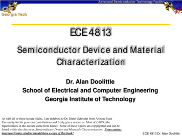
How Polarizers work ?G GD ε 0ε E ε xx ε xy ε xz Ex Dx Dy ε 0 ε yx ε yy ε yz E y ε ε ε E D z zx zy zz z How Polarizers work ? ε xx ε xy ε xz ε xx 0 0 ε ε yx ε yy ε yz 0 ε yy 0 ε ε ε 0 0 ε zz zx zy zz Examples:Wire-grid polarizerElectro-absorption modulatorBrewster polarizer9How Polarizers work ?Birefringentpolarizers10How Polarizers work ? ε xx ε xy ε xz n 2 e 0 0 ε ε yx ε yy ε yz 0 n 2O 0 ε ε ε 0 0 n 2 O zx zy zz Thin-film polarizers (narrow band) Optical axis ZGGD εˆ (ω ) Eε zz (ω ) ε xx (ω ) ε yy (ω )1112
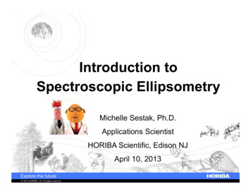
Stokes Parameters for Polarization of Electromagnetic WaveCR Stokes Parameters, Intensity, and Poincare sphereStokes vector:S0 I 0S1 I x I yS 2 I π / 4 I π / 4S3 Iσ Iσ S0 G S S 1 S2 S3 V2γH VHCL3j 13P j 1S02j[P 1 (?); P 0 (?)]13Change of Polarization of Electromagnetic WaveUnpolarized light 1 0 GS S0 0 0 1 1 GSl S 0 0 0 V2γH VHCLElliptically polarized light 1 0 GSc S0 0 1 1 G cos 2ψ S S0 sin 2ψ cos sin 2ψ sin 14Relationship between different representations of the lightPolarization Optical elements, like polarizers and returders, are equivalent torotation of the Stokes vector around their characteristic vectors by acertain angle. S0 G S1 S2 S2 S3 π 2 ΨLinearly and circularlypolarized lightS0 2 S j 2 SCR Stokes Parameters, Intensity, and Poincare sphereπ 2 ΨI 0 Ex* Ex E y E *yStokes Parameters for Polarization of Electromagnetic Wave S0 G S1 S1 S2 S3 Stokes parameters and J-Jones matrix elements for time-averagedquantities: S0 *Ex E *y J xx J xy Ex ExG S1 ˆ J S S2 E y E *y J xx J xy E y Ex* S3 CRπ 2 Ψ S0 1 S 1 1 S2 0 S3 02γ150 0 1 J xx 0 0 -1 J xy 1 1 0 J yx -i i 0 J yy V2γHH VCL16
Muller Matrices for Polarization of Electromagnetic Wave Muller MatricesMM and Polarization Muller Matrices for some ideal common optical elements:17Polarization of Electromagnetic WaveAnother view at Ellipsometry18Description of Polarization changes Muller Matrix for rotation of the coordinate system: Muller Matrices for sample measured in Ellipsometry:SM cos 2ψ 1 cos 2ψ1 00 0 0 1 0RS 0 0 00 sin2ψ cos sin2ψ cos sin2ψ cos sin2ψ cos 0ρ 0rprs00cos2θ sin2θ-sin2θ cos2θ000 0 0 1 tan Ψ ei φ0 variable, tanΨ rprs, δ p δs1920
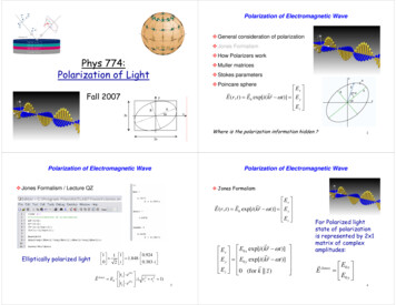
Jones matrices and EllipsometryWhat is far-IR Ellipsometry? Jones matrix representation for Ellipsometry measurement:E Jones out Jˆ E Jons inE Jones out Jˆn. i polarizer Jˆrotate ( A As ) Jˆsample Jˆrotate ( ( P Ps )) Jˆn. i polarizer E Jons inFar-Infrared Ellipsometry is a technique which allows one to measure very accurately and with highreproducibility the complex dielectric function ε(ω) ε(ω)1 i ε(ω)2 of oxide thin films and singlecrystals. It measures the change in polarization of Infrared light upon non-normal reflection on the surfaceof a sample to be studied. To extend the Ellipsometry technique to the Far-Infrared part of theelectromagnetic spectrum, we are going to carry out these experiments at Brookhaven National Laboratory,National Synchrotron Light Source. Synchrotron light provides three orders of magnitude more brilliant 21light in the Far-Infrared as compared to conventionally available light sources, like mercury arc lamps.Limitations of the previous formalismUsing example of birefringenceGGˆ()D εωEOptical axis Zε zz (ω ) ε xx (ω ) ε yy (ω )What if we have simultaneousbirefringence and optical activity?Answer:we will use Jones N – matrices fornon-local effects2322
Elliptically polarized light 0 1 0 0 1 SSc . Far-Infrared Ellipsometry is a technique which allows one to measure very accurately and with high reproducibility the complex dielectric function ε(ω) ε(ω)1 i ε(ω)2 of oxide thin films and single crystals. It measures the change in polarizati