Transcription
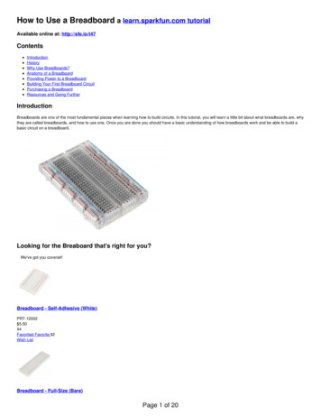
How to Use a Breadboard a learn.sparkfun.com tutorialAvailable online at: http://sfe.io/t47ContentsIntroductionHistoryWhy Use Breadboards?Anatomy of a BreadboardProviding Power to a BreadboardBuilding Your First Breadboard CircuitPurchasing a BreadboardResources and Going FurtherIntroductionBreadboards are one of the most fundamental pieces when learning how to build circuits. In this tutorial, you will learn a little bit about what breadboards are, whythey are called breadboards, and how to use one. Once you are done you should have a basic understanding of how breadboards work and be able to build abasic circuit on a breadboard.Looking for the Breaboard that's right for you?We've got you covered!Breadboard - Self-Adhesive (White)PRT-12002 5.5044Favorited Favorite 92Wish ListBreadboard - Full-Size (Bare)Page 1 of 20
PRT-12615 6.5031Favorited Favorite 50Wish ListBreadboard - GiantPRT-12614 21.5026Favorited Favorite 59Wish ListBreadboard - ClassicPRT-00112 10.9517Favorited Favorite 27Wish ListBreadboard - Translucent Self-Adhesive (Clear)PRT-09567 5.5015Favorited Favorite 35Wish ListBreadboard - Mini Modular (Red)PRT-12044 4.50Favorited Favorite 12Wish ListPage 2 of 20
Breadboard - Translucent Self-Adhesive (Red)PRT-11317 5.501Favorited Favorite 20Wish ListBreadboard - Mini Modular (Black)PRT-12047 4.50Favorited Favorite 20Wish ListSee all of our breadboard optionsSuggested ReadingHere are some tutorials and concepts you may want to explore before learning about breadboards:Connector BasicsConnectors are a major source of confusion for people just beginning electronics. The number of different options, terms, and names of connectors can makeselecting one, or finding the one you need, daunting. This article will help you get a jump on the world of connectors.Favorited Favorite 52What is a Circuit?Every electrical project starts with a circuit. Don't know what a circuit is? We're here to help.Favorited Favorite 73Voltage, Current, Resistance, and Ohm's LawLearn about Ohm's Law, one of the most fundamental equations in all electrical engineering.Favorited Favorite 123Working with WireHow to strip, crimp, and work with wire.Favorited Favorite 45How to Read a SchematicAn overview of component circuit symbols, and tips and tricks for better schematic reading. Click here, and become schematic-literate today!Favorited Favorite 106How to Use a MultimeterLearn the basics of using a multimeter to measure continuity, voltage, resistance and current.Favorited Favorite 63HistoryIf you wanted to build a circuit prior to the 1960s, chances are you would have used a technique calledwire-wrap. Wire wrap is a process that involves wrappingwires around conductive posts attached to a perfboard (a.k.a. a protoboard). As you can see, the process can get rather complex very quickly.Although thismethod is still used today, there is something that makes prototyping much easier, breadboards!Page 3 of 20
A wire-wrap circuit (image courtesy of Wikipedia user Wikinaut)What’s in a Name?When you picture a breadboard in your head, you may envision a big piece of wood and a large loaf of freshly baked bread. You wouldn’t be too far off either.Bread on a breadboardSo why do we call this electronic “circuit builder” a breadboard? Many years ago, when electronics were big and bulky, people would grab their mom’sbreadboard, a few nails or thumbtacks, and start connecting wires onto the board to give themselves a platform on which to build their circuits.Circuit on an "original" breadboard (image courtesy of mischka and their awesome literal breadboard tutorial)Page 4 of 20
Since then, electronic components have gotten a lot smaller, and we’ve come up with better ways to connect circuits, making moms all over the world happy tohave their breadboards back. However, we are stuck with the confusing name. Technically, these are still breadboards, but this discussion is going to be onmodern, "solderless" breadboards.Why Use Breadboards?An electronics breadboard (as opposed to the type on which sandwiches are made) is actually referring to asolderless breadboard. These are great units formaking temporary circuits and prototyping, and they require absolutely no soldering.Prototyping is the process of testing out an idea by creating a preliminary model from which other forms are developed or copied, and it is one of the mostcommon uses for breadboards. If you aren’t sure how a circuit will react under a given set of parameters, it’s best to build a prototype and test it out.For those new to electronics and circuits, breadboards are often the best place to start. That is the real beauty of breadboards--they can house both the simplestcircuit as well as very complex circuits. As you'll see later in this tutorial, if your circuit outgrows its current breadboard, others can be be attached toaccommodate circuits of all sizes and complexities.Another common use of breadboards is testing out new parts, such as Integrated circuits (ICs). When you are trying to figure out how a part works and constantlyrewiring things, you don’t want to have to solder your connections each time.As mentioned, you don’t always want the circuit you build to be permanent. When trying to duplicate a customer’s problem, SparkFun’s Technical Support teamwill often use breadboards to build, test, and analyze the circuit. They can connect the parts the customer has, and once they’ve gotten the circuit setup andfigured out the problem, they can take everything apart and put it aside for the next time they need to do some troubleshooting.A circuit built on a solderless breadboardAnatomy of a BreadboardPage 5 of 20
The major features of a BreadboardThe best way to explain how a breadboard works is to take it apart and see what’s inside. Using a smaller breadboard it’s easier to see just how they function.Terminal StripsHere we have a breadboard where the adhesive backing has been removed. You can see lots of horizontal rows of metal strips on the bottom of the breadboard.A SparkFun Mini Breadboard from the top (left) and the same breadboard flipped over with the adhesive back removed (right).The tops of the metal rows have little clips that hide under the plastic holes. Each metal strip and socket is spaced with a standard pitch of 0.1" (2.54mm). Theseclips allow you to stick a wire or the leg of a component into the exposed holes on a breadboard, which then hold it in place.A single strip of conductive metal removed from the above breadboard.Page 6 of 20
Once inserted that component will be electrically connected to anything else placed in that row. This is because the metal rows are conductive and allow currentto flow from any point in that strip.Notice that there are only five clips on this strip. This is typical on almost all breadboards. Thus, you can only have up to five components connected in oneparticular section of the breadboard. The row has ten holes, so why can you only connect five components? You’ll also notice that each horizontal row isseparated by a ravine, or crevasse, in the middle of the breadboard. This ravine isolates both sides of a given row from one another, and they are not electricallyconnected. We’ll discuss the purpose of this in just a bit, but, for now, just know that each side of a given row is disconnected from the other, leaving you with fivespots for components on either side.An LED inserted into a breadboard. Notice how each leg of the LED is placed on either side of the ravine. This prevents the connections to the LED from beingshorted.Power RailsNow that we’ve seen how the connections in a breadboard are made, let’s look at a larger, more typical breadboard. Aside from horizontal rows, breadboardsusually have what are called power rails that run vertically along the sides.A medium-size breadboard with the adhesive back removed to expose the power rails.These power rails are metal strips that are identical to the ones that run horizontally, except they are, typically*, all connected. When building a circuit, you tendto need power in lots of different places. The power rails give you lots of easy access to power wherever you need it in your circuit. Usually they will be labeledwith a ‘ ’ and a ‘-’ and have a red and blue or black stripe, to indicate the positive and negative side.It is important to be aware that the power rails on either side are not connected, so if you want the same power source on both sides, you will need to connect thetwo sides with some jumper wires. Keep in mind that the markings are there just as a reference. There is no rule that says you have to plug power into the ' ' railand ground into the '-'rail, though it's good practice to keep everything in order.Page 7 of 20
Two jumper wires used to connect the power rails on both sides. Always attach the ‘ ’ to ‘ ’ and the ‘-’ to ‘-’.DIP SupportEarlier we mentioned the ravine that isolates the two sides of a breadboard. This ravine serves a very important purpose. Manyintegrated circuits, often referredto as ICs or, simply, chips, are manufactured specifically to fit onto breadboards. In order to minimize the amount of space they take up on the breadboard, theycome in what is known as a Dual in-line Package, or DIP.These DIP chips (salsa anyone?) have legs that come out of both sides and fit perfectly over that ravine. Since each leg on the IC is unique, we don’t want bothsides to be connected to each other. That is where the separation in the middle of the board comes in handy. Thus, we can connect components to each side ofthe IC without interfering with the functionality of the leg on the opposite side.Two DIP ICs, the LM358 (top), a very common op-amp, and the ever-popularATmega328 microcontroller (bottom).Rows and ColumnsYou may have noticed that many breadboards have numbers and letters marked on various rows and columns. These don't serve any purpose other than tohelp guide you when building your circuit. Circuits can get complicated quickly, and all it takes is one misplaced leg of a component to make the entire circuitmalfunction or not work at all. If you know the row number of the connection you are trying to make, it makes it much simpler to plug a wire into that numberrather than eyeballing it.Page 8 of 20
These are also helpful when using instruction booklets, such as the one found in theSparkFun Inventor’s Kit. Many books and guides have circuit diagrams foryou to follow along while building your circuit. Just remember that the circuit you’re building doesn’t have to be in the exact same location on the breadboard asthe one in the book. In fact, it doesn’t even have to look similar. As long as all the electrical connections are being made, you can build your circuit any way you’dlike!Binding PostsSome breadboards come on a platform that has binding posts attached to it. These posts allow you to connect all kinds of different power sources to yourbreadboard. We'll cover these more in the next section.Page 9 of 20
Binding Post for Banana Cables and WiresBinding Posts on Classic BreadboardOther FeaturesWhen building your circuit, you are not confined to stay on just one breadboard. Some circuits will require a lot more space. Many breadboards have littlenubbins and slots on the sides, and some even have them on the tops and bottoms. These allow you to connect multiple breadboards together to form theultimate prototyping surface.Four SparkFun mini breadboards connected together.Some breadboards also have an adhesive backing that allow you to stick them to many different surfaces. These can come in handy if you want to attach yourbreadboard to the inside on an enclosure or other project case.Note: Some larger breadboards will often isolate one half of the breadboard’s power rails form the other half (think top and bottom half, not the sides). This isconvenient if you have two different voltages with which you need to power your circuit, such as 3.3V and 5V. However, if you’re unaware whether the power railsare or aren’t isolated, it can often lead to issues while building your circuit. It’s always a good idea to use a multimeter to check for the absence or presence ofcontinuity in your breadboard’s power rails.Providing Power to a BreadboardWhen it comes to providing power to you breadboard, there are numerous options.Borrowing from Other Power SourcesIf you are working with a development board such as an Arduino, then you can simply pull power from the Arduino’s female headers. The Arduino has multiplepower and ground pins that you can connect to the power rails or other rows on a breadboard.Page 10 of 20
Connecting the Ground (GND) pin from an Arduino to a row on a mini breadboard. Now any leg or wire connected to that row will also be connected to Ground.The Arduino usually gets its power from the USB port on a computer or an external power supply such as abattery pack or a wall wart.Binding PostsAs mentioned in the previous section, some breadboards have binding posts that allow you to connect external power sources.The first step to using the binding posts is to connect them to the breadboard using some jumper wires. Although it would seem that the posts are connected tothe breadboard, they are not. If they were, you would be limited to where you could and couldn’t provide power. As we’ve seen, breadboards are meant to betotally customizable, so it would make sense that the binding posts are no different.With that, we have to connect wires to the posts in order to connect them to the breadboard. To do that, unscrew the post until the hole going through it isexposed. Slide the stripped end of your jumper wire through the hole, and screw the post back down until the wire is firmly connected.Typically, you only need to connect a power and ground wire from the posts to the breadboard. If you need an alternate power source, you can use the third post.Now your posts are connected to the the breadboard, but there is still no power. You can use many different methods to connect power to the posts, and, thus,to the breadboard.Benchtop Power SuppliesMany electronics labs have benchtop power supplies that allow you to provide a wide range of voltage and current to your circuit. Using abanana connector youcan provide power from the supply to the binding posts.Page 11 of 20
A breadboard being powered through the binding posts from banana cables.Alternatively, you could use alligator clips, IC hooks, or any other cables with a banana connection to hook your breadboard up to a number of different supplies.Another method of using the binding posts is to solder abarrel jack to some wires, and then connect them to the binding posts. This is a more advancedtechnique, and it requires some intermediate soldering skills.The barrel jack is soldered to two wires that share the same holes on the binding posts as the wires going to the breadboard. If your breadboard doesn't havebinding posts, you could just plug the wires from the barrel jack directly into the power rails.Breadboard Power SuppliesYet another method for powering your breadboard is to use one of the many breadboard power supplies available. SparkFun carriesa number of kits and boardsthat you can use to plug power directly into your breadboard. Some allow you to plug a wall wart directly into the breadboard. Others allow you to pull powerdirectly from your computer via the USB connections. And, almost all of them have the capability to adjust the voltage, giving you a full range of the commonvoltages needed when building circuits.Page 12 of 20
A SparkFun USB Breadboard Power Supply that pulls power from your computer's USB and has the option to choose between 3.3V and 5V.Building Your First Breadboard CircuitNow that we're familiar with the internals of a breadboard and how to provide power to them, what do we do with them? We are going to start with a simplecircuit.What You’ll NeedHere is a parts list to follow along with this circuit. If you have other electronic bits and pieces, feel free to use them and change the circuit up. Remember, thereis often more ways than one to build any given circuit. Some even have dozens of different ways that you can build them.Breadboard Tutorial WishList SparkFun Wish ListResistor 330 Ohm 1/4 Watt PTH - 20 pack (Thick Leads)PRT-14490Momentary Pushbutton Switch - 12mm SquareCOM-09190This is a standard 12mm square momentary button. What we really like is the large button head and good tactile feel (it 'clicks' really well). This bu Hook-Up Wire - Assortment (Solid Core, 22 AWG)PRT-11367An assortment of colored wires: you know it's a beautiful thing. Six different colors of solid core wire in a cardboard dispenser box. Sit this on you LED Mixed Bag - 5mmCOM-09881We all know that you can never get too many LEDs. Don't worry, we've got you covered. This is a mixed pack of 26 LEDs all conveniently packaged in a n Wall Adapter Power Supply - 9VDC 650mATOL-00298High quality switching 'wall wart' AC to DC 9V 650mA wall power supply manufactured specifically for Spark Fun Electronics. These are switch mode powe Breadboard - Translucent Self-Adhesive (Clear)PRT-09567**Description**: Ever wonder what goes on inside these things? Well this clear bread board might enlighten. Beyond the clear plastic, this is really This wish list assumes you don't have any parts/tools and is generous with quantities etc. For example, you only need one LED for this project, but the pack listedWire Strippers - 20-30AWGhas 20 LEDs TOL-14763in it. The same is true with the hook-up wire. You don't need that much (or all those colors), but if you keep playing with circuits, it could come inhandy. If you don't want the higher quantities check the bottom of the product pages in the section called "Related Products" and you should be able to findsmaller quantities. Also, the breadboard power supply doesn't have headers, if you know how to solder and have the tools, solder the headers on yourself. If not,SparkFun Breadboard Power Supply Stick - 5V/3.3Vsolderless headershave been included in the wishlist as well.PRT-13032This is a very simple board that takes a 6-12V input voltage and outputs a selectable 5V or 3.3V regulated voltage. All headers are 0.1" pitch for sim Build the CircuitBreak Away Headers - StraightPRT-00116Warning! Whenusing the breadboard power supply stick, make sure to insert the GND pins with the –"" rail and the VCC to the " " rail. This will help reduce theA row of headers - break to fit. 40 pins that can be cut to any size. Used with custom PCBs or general custom headers.**Features: *** Pin Style: Squar Page 13 of 20
chance of applying reverse polarity to your circuit.Here is a small circuit on a breadboard. The red board you see is theBreadboard Power Supply Stick with headers soldered to the PCB. The breadboard powersupply stick regulates voltage from a 9V wall wart to either 5V or 3.3V to the power rails.A simple circuit, involving a button, an LED, and a resistor, built two different ways.The circuit goes as follows:There is a wire connecting the VCC power rail to the positive, anode leg of an LED.The negative, cathode leg of the LED is connected to a 330Ω resistor.The resistor is then connected to a button.When the button is pushed, it connects the circuit to ground completing the circuit and turning on the LED.Circuit SchematicsWe cover how to read a schematic inanother tutorial. However, it is a very important part of building circuits, so it will be covered here in short.Schematics are universal pictograms that allow people all over the world to understand and build electronics. Every electronic component has a very uniqueschematic symbol. These symbols are then assembled into circuits using a variety of programs. You could also draw them out by hand. If you want to divedeeper in the world of electronics and circuit building, learning to read schematics is a very important step in doing so.Here we have a schematic for the above circuit. Power (assuming the switch is flipped to the 5V side) is represented by the arrow at the top. It then goes to theLED (the triangle and line with arrows emitting out of it). The LED is then connected to the resistor (the squiggly line). That is connected to the button (the latchlooking symbol). Last the button is connect to ground (the horizontal line at the bottom).This may seem like a funny way to draw a circuit, but it is a fundamental process that has been around for decades. Schematics allow people from differentnationalities and languages to build and collaborate on circuits designed by anyone. As mentioned, you can build a circuit in many different ways, but, as thisschematic shows, there are certain connections that must be made. Diverging from this schematic will give you an entirely different circuit.Practice Makes PerfectPage 14 of 20
The last bit of knowledge to leave you with is that there are tons of resources and programs you can use to build circuits without having to actually use yourbreadboard. One very common program used by SparkFun is Fritzing. Fritzing is a free program that allows you to build your own circuits on a virtualbreadboard. It also provides schematic views for all the circuits you build. Here we can see the same circuits as above built using Fritzing.Notice that the green lines indicate to which rows and columns each component is connected.There are many other programs like Fritzing. Some are free, and some are paid. Some will even allow you to build a circuit and test its functionality throughsimulations. Go explore the internet, and find the tools that work best for you.Purchasing a BreadboardA great way to start using breadboards is to purchase one as part of a kit. The Sparkfun Inventor's Kit includes everything you need to complete 16 differentcircuits.SparkFun Inventor's Kit - v4.1KIT-15267 106.9511Favorited Favorite 37Wish ListBreadboardsWe've also listed a few basic stand-alone breadboards in different sizes for your projects.Page 15 of 20
Breadboard - ClassicPRT-00112 10.9517Favorited Favorite 27Wish ListBreadboard - Translucent Self-Adhesive (Clear)PRT-09567 5.5015Favorited Favorite 35Wish ListBreadboard - Mini Modular (Red)PRT-12044 4.50Favorited Favorite 12Wish ListSTEMTera (Black)DEV-14082 48.5011Favorited Favorite 80Wish ListClick Here for More BreadboardsJumper WiresLooking for ways to connect easily to your boards and ICs on a breadboard? Check out the following jumper wires.Page 16 of 20
Jumper Wire Kit - 140pcsPRT-00124 6.509Favorited Favorite 55Wish ListAlligator Clip with Pigtail (10 Pack)CAB-14303 7.504Favorited Favorite 12Wish ListIC Hook with PigtailCAB-09741 5.5010Favorited Favorite 28Wish ListIC Hook Test LeadsCAB-00501 9.953Favorited Favorite 9Wish ListJumper Wires Premium 6" F/F Pack of 10Page 17 of 20
PRT-08430 4.501Favorited Favorite 13Wish ListJumper Wires Premium 6" M/M Pack of 10PRT-08431 4.502Favorited Favorite 11Wish ListJumper Wires Premium 6" M/F Pack of 10PRT-09140 4.501Favorited Favorite 15Wish ListClick Here for More WiresSolderable Breadboards and ProtoboardsWhen you are finished prototyping on a breadboard, you can solder the circuit to aPCB for a more secure connection.SparkFun Solder-able BreadboardPRT-12070 5.5017Favorited Favorite 57Wish ListSparkFun Solder-able Breadboard - MiniPRT-12702 3.5014Favorited Favorite 41Wish ListPage 18 of 20
SparkFun Solder-able Breadboard - LargePRT-12699 9.955Favorited Favorite 19Wish ListSparkFun ProtoShield KitDEV-13820 12.503Favorited Favorite 16Wish ListClick Here for More Prototyping BoardsInterested in learning more foundational topics?See our Engineering Essentials page for a full list of cornerstone topics surrounding electrical engineering.Take me there!Resources and Going FurtherHopefully you now have a better understanding of what a breadboard is and how it works. Now the real fun begins. We've barely scratched the surface ofbuilding circuits on breadboards. Here are some other tutorials you can check out to learn more about components and how to integrate them into yourbreadboard circuits.ResistorsCapacitorsDiodesLEDsShift RegistersIntegrated CircuitsEducators may be interested in these links.Building Giant BreadboardsUsing the SIK to Teach Breadboard CircuitsOr, if you have mastered your circuit building skills and want to move to the next level, check out these tutorials.How to SolderSolderable Breadboard Hookup GuidePage 19 of 20
PCB BasicsElectronics AssemblyHow to use Eagle the PCB Layout Editorlearn.sparkfun.com CC BY-SA 3.0 SparkFun Electronics Niwot, ColoradoPage 20 of 20
breadboard, a few nails or thumbtacks, and start connecting wires onto the board to give themselves a platform on which to build their circuits. Circuit on an "original" breadboard (image courtesy ofmischka and their awesome li