Transcription
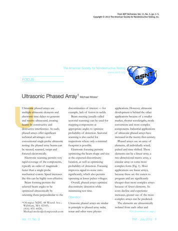
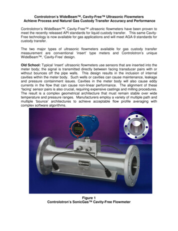
Volume 2, Issue 4, April– 2017International Journal of Innovative Science and Research TechnologyISSN No: - 2456 - 2165Automatic Braking System Using Ultrasonic SensorJ.V.Sai Ram, K.M.S.V.Manikanta, G.Pavanth, B.Jagadeep ,Dr. B.Raghu KumarABSTRACT:- When compared with olden days life span ofhuman is reduced. Death rate due to accident is drasticallyincreased because vehicles usage is increasing by day byday. Due to brake failure so many accidents are occurringso when we control the brake by automatically we canreduce the effect of accident. A Ultrasonic setup is placed infront of vehicle and that setup consists of an emitter and areceiver. Ultrasonic emitter always emits the ultrasonicwaves, whenever a obstacle is detected then wave getsreflected and receiver receives the signal. Reflected wavesends the signal to the Aurduino Nano from that basedupon distance of object it actuates the buzzer or brakes.Brakes are actuated by using Solenoid valve. Solenoidvalve operated by electrical signal and it actuates brakes byusing pneumatics. UBS car provides the glimpse into thefuture of automotive safety. By UBS system we can preventmore accidents and save more lives.Keywords :- Braking system, Ultrasonic sensor, Aurduino.I.INTRODUCTIONB. Introduction To BrakingA Brake is a mechanical device used to slowing or stopping amoving vehicle i.e. wheel, axle, or to prevent its motion, mostoften accomplished by means of friction.Stopping distance consists of three factors: Driver’s reaction timeBrake lagBraking distanceC. Design and FunctionAir brake system is used heavy vehicles because they needhigher impact of braking . Piston cylinder arrangement ismade for braking. Compressed air is used to hit the brakes, forthat a compressor is provided in the vehicles. Braking time issmall and less by using pneumatics in heavy vehicles.[2]D. Design and ConstructionThe first demonstration of forward collision avoidancewas performed in 1995 by a team of scientists and engineersat Hughes Research Laboratories in Malibu, California. Theproject was funded by Delco Electronics, and was led by HRLphysicist Ross D. Olney. A small custom fabricatedradar-head was developed specifically for this automotiveapplication at 77 GHz. The forward radar-head, plus the signalprocessing unit and visual-audio-tactile feedbacks were firstintegrated into a Volvo S40, and shortly thereafter into aCadillac STS.Depending on the specimen specification, there are multipleforms of body constructions:A.E. Hand operated leverN.H.A.IReportAccording to the N.H.A.I data of number of accidentsoccurred during the 2011 analysis. Accidents 4.97 lakh(annual) i.e. (1 every minute) and the deaths for the accidentsare recorded as 1,42,485 Directional control valves(hand operated value) are one of themost fundamental parts in hydraulic machinery as well aspneumatic machinery. They allow fluid flow into differentpaths from one or more sources. They usually consist of aspool inside a cylinder which is mechanically or electricallycontrolled.Fig.1.3 Causes of accidents in 2011 analysis (Courtesy byN.H.A.I)IJISRT17AP101Tie rod cylinders: The most common cylinderconstructions that can be used in many types ofloads. Has been proven to be the safest form.Flanged-type cylinders: Fixed flanges are added tothe ends of cylinder, however, this form ofconstruction is more common in hydraulic cylinderconstruction.www.ijisrt.comFig 2.1 Hand operated directional valve398
Volume 2, Issue 4, April– 2017International Journal of Innovative Science and Research TechnologyISSN No: - 2456 - 2165II.BRAKING CIRCUITB. Aurdunio NanoIn this project major part of work comes from electronics toactuate the solenoid valve. Because solenoid valve is anelectromagnetic component which is used to actuate the brakecylinders. The components used in the circuit are listed inbelow:The Arduino Nano is a small, complete, andbreadboard-friendly board based on the ATmega328 (ArduinoNano 3.x). It has more or less the same functionality of theArduino Duemilanove, but in a different package. It lacksonly a DC power jack, and works with a Mini-B USB cableinstead of a standard one.C. PowerThe Arduino Nano can be powered via the Mini-B USBconnection, 6-20V unregulated external power supply (pin30), or 5V regulated external power supply (pin 27). Thepower source is automatically selected to the highest voltagesource.D. MemoryFig 3.0.1 Circuit diagram of the braking circuitAnalog electronic circuits are those in which current orvoltage may vary continuously with time to correspond to theinformation being represented. Analog circuitry is constructedfrom two fundamental building blocks: series and parallelcircuits. In a series circuit, the same current passes through aseries of components. A string of Christmas lights is a goodexample of a series circuit: if one goes out, they all do. In aparallel circuit, all the components are connected to the samevoltage, and the current divides between the variouscomponents according to their resistance.The ATmega328 has 32 KB, (also with 2 KB used for thebootloader. The ATmega328 has 2 KB of SRAM and 1 KB ofEEPROM.E. Input and OutputEach of the 14 digital pins on the Nano can be used as aninput or output, using pinMode(), digitalWrite(), anddigitalRead() functions. They operate at 5 volts. Each pin canprovide or receive a maximum of 40 mA and has an internalpull-up resistor (disconnected by default) of 20-50 kOhms. Inaddition, some pins have specialized functions.[4]A. Ultrasonic transducersF. CommunicationUltrasonic transducers are used to emit the ultrasonic waveswith high frequency. These transducers are operated by usingelectrical current. In this project 12V battery is used switch onthe source. [3]Distance Time x Speed of Sound divided by 2Time the time between when an ultrasonic wave istransmitted and when it is received you divide this number by2 because the sound wave has to travel to the object and back.IJISRT17AP101The Arduino Nano has a number of facilities forcommunicating with a computer, another Arduino, or othermicrocontrollers. The ATmega328 provide UART TTL (5V)serial communication, which is available on digital pins 0(RX) and 1 (TX). An FTDI FT232RL on the board channelsthis serial communication over USB and the FTDI drivers(included with the Arduino software) provide a virtual comport to software on the computer. The Arduino softwareincludes a serial monitor which allows simple textual data tobe sent to and from the Arduino board. The RX and TX LEDson the board will flash when data is being transmitted via theFTDI chip and USB connection to the computer (but not forserial communication on pins 0 and 1).Program Used For Micro Controllerconst int trigPin 3;const int echoPin 2;const int solenoid 5;const int buzzer 6;void setup(){Serial.begin(9600);pinMode(trigPin, OUTPUT);pinMode(echoPin, INPUT);www.ijisrt.com399
Volume 2, Issue 4, April– 2017International Journal of Innovative Science and Research TechnologyISSN No: - 2456 - 2165pinMode(solenoid, OUTPUT);pinMode(buzzer, OUTPUT);}void loop(){long duration, cm;digitalWrite(trigPin, LOW);delayMicroseconds(2);digitalWrite(trigPin, HIGH);delayMicroseconds(10);digitalWrite(trigPin, LOW);duration pulseIn(echoPin, HIGH);cm duration/ 29 / 2;Serial.println(cm);if(cm 1);delay(2000);}else delay(200);consists of one input and two outputs. Solenoid valveconnects in between air reservoir and brakes to apply brakes.When ever signal achived from circuit the valve changes itsdirection and air flows to brakes. When the switch is offcondition the direction changes to reverse of braking. [5]III.LITARATURE REVIEWIn automation field, designers have proposed severalenhancements A precise shortrange radar system wasdeveloped for anti -collision applications where automaticbraking is applied in response to detection of a collision riskwhere a very high probability of detection is accompanied bya very low level of false alarms. A brake strategy for anautomatic parking system of vehicle has proposed brakecontroller which work with the automatic parking system andmake the process of parking smooth and stable. Autonomousantilock braking system (ABS) system which can take overthe traction control of the vehicle is developed for a fourwheel vehicle. ABS is a braking system that maintains controlover the directional stability of the vehicle during emergencybraking or braking on slippery roads by preventing wheellock-up. There have been considerable advancesin modernvehicle braking systems in recent years.A. Implementation of Automatic Reverse Braking System,FPGA Divya Thakur Prof. A. P. Thakare.Auto-Braking System using Sensor was proposed toprevent front-end, rear-end, right-turn and left -turn accidentson roads. This module can detect the distance between frontvehicle and driver’s vehicle to keep a constant distance using asensor and operate the brake system.Fig 3.2.1 Aurduino NanoG. DriverThe ULN2803APG / AFWG Series are high voltage,high current darlington drivers comprised of eight NPNDarlington pairs. All units feature integral clamp diodes forswitching inductive loads. Applications include relay,hammer, lamp and display (LED) drivers.B. Review of Speed Control and Automatic Braking SystemGopal P. Gawande, Shruti V. Gavhale , Irshad A. Zariye ,Sagar P. Ritpurkar EXTC Department, AVBIT, Pawnar(WARDHA), Maharashtra (INDIA)Fig 3.3.1DriverH. 3/2 way solenoid valvesSolenoid valve is a device which is used to control thedirection of air by using electrical current. The solenoid valveIJISRT17AP101All the above proposed design models contributed tosafety of vehicles and pedestrians. It prevented rear end crashes, provided ABS for sharp turns or slippery roads. But allthese are applicable for vehicles running in conventionaldirection, so we need to develop systems which enhances theperformance and safety of vehicles when it moves in reversedirection. A model designed on reversing of vehicles provideddetection of obstacle , speed control mechanism based onbinocular cameras. Thus, in this paper we propose “AutomaticReverse Braking system” to prevent collision by using sensorsto detect obstacles. The “Automatic Reverse Braking system”is processing the sensor data and controlling the vehicle toprevent accidents.The proposed work is likely to control the speed ofvehicle and automatic format braking system. It is divided intothree main steps; 1. Detect the object (Hurdle) from vehicle. 2.Control the speed of vehicle. 3. Automatic braking system. Thewww.ijisrt.com400
Volume 2, Issue 4, April– 2017International Journal of Innovative Science and Research TechnologyISSN No: - 2456 - 2165proposed method will automatically inform about the hurdle inthe path of the vehicle on the display with the help of differentsensors. Ultrasonic sensors are connected in the vehicle tosense the object (Hurdle) and then send signals to thecontroller. The controller takes different actions based on thesesignals in order to create a safe environment for the driver.After detecting the obstacle in front of the car, we will directlyview the distance between the car and obstacle on the LEDdisplay. When the distance between two cars or distancebetween cars & obstacle is very small, means if accidents likesituation are detected by IR sensor then the automatic brakingsystem is activated.IV.WORKING AND DESIGNA. WorkingThe compressed air from cylinder as shown in Fig 5.1.1 is builtby the pressure difference from the atmosphere. The air passesthrough the pneumatic pipes for storage in the reservoir.Fig 5.1.5 BuzzerNearly 10cms the air pushes the solenoid valve and hitsthe cylinder piston as shown in fig 5.1.6 and cylinder expandsas shown in fig 5.1.7 and pushes the cam to apply brake so thatthe brake pads move towards the drum and the brake is applied.Fig5.1.6 Piston cylinderIf the circuit need not to be required during certain times ofsituation the hand lever directional valve is used to apply brake.The directional valve used has a lever to apply brake and togive way to passage of pressurized air.Fig 5.1.1 Air compressorFig 5.1.7 Expand cylinder.The frame of this project as shown in fig 5.1.8 is buildwith ms pipe material of 1” tube and shafts are designedaccording to the bearing as shownfig5.1.9Fig 5.1.4 DriverThe compressed air passes through the pipes and reaches thereservoir as shown in Fig 5.1.1 and collect it there and is usedfor reserve purpose.Fig 5.1.8 Frame and shafts with tyresFig 5.1.2 Air Storage tankIJISRT17AP101And tyres are take as scooty tyres and gives the body a strongstructure to with stand on it. The bolts and nuts as shown in figwww.ijisrt.com401
Volume 2, Issue 4, April– 2017International Journal of Innovative Science and Research TechnologyISSN No: - 2456 - 21655.1.10 are used for fitting all accessories on the frame likewooden plank, bearing, tyres etc which the vehicle comes to a complete stop from the presentspeed. It is calculated by using following formula.Braking Distance V / 2µg (meter)WhereV Velocity of the vehicle (m/s)µ Coefficient of friction of road 0.8g Acceleration due to gravity 9.81(m/s2 )Fig 5.1.10 FittingsThe pneumatic pipes are loaded non leakage of air pipes asshown in fig 5.1.10. Cylinder and pipes are connected by Tshape pipes. as shown in fig 5.1.11.In this formula the condition of brakes and the roadconditions are not considered for coefficient of friction µ.Table showing braking distance:Velocity (km/hr)Braking Distance (m)6017.695012.28407.86304.42050.12Table 5.2.1 Velocity vs. Braking distancesFig 5.1.11 Valve fitting of pipesA. FabricationMetal fabrication is the building of metal structures by cutting,bending, and assembling processes. It is a value added processthat involves the construction of machines and structures fromvarious raw materials. A workshop will bid on a job, usuallybased on the engineering drawings, and if awarded the contractwill build the product. Large workshops will employ amultitude of value added processes in one plant or facilityincluding welding, cutting, forming and machining.B. Raw materialsFig 5.1.12 Actual working of Braking systemThe above figure shows the actual working of “AutomaticBraking System using Ultrasonic waves. Mechanical andelectrical breaks both systems are placed in the unit, Wheneverthe electrical system fails then we can normally apply thebrakes. So there is no problem with the failure of electricalbraking. a buzzer indication will always indicated when theobstacle faced, so driver can easily hit the brake by using brakepedal.V.DESIGN AND CALCULATIONThe braking distance is the main factor considered in thissystem. Braking distance for a particular speed is the distancebetween the point of application of the brakes and the point atIJISRT17AP101Ram material used in the project is mild steel. for the frameof the vehicle and shaft to transmit the power to wheels equallyfor all the four wheels. and wood platform for the support ofrequire components on the vehicle like air reservoir, electricalcircuit , brake cylinders etc Steel is an alloy of iron and otherelements, primarily carbon, which is widely used inconstruction and other applications because of its high tensilestrength and low cost. Steel's base metal is iron, which is ableto take on two crystalline forms (allotropic forms), bodycentered cubic and face centered cubic (FCC), depending on itstemperature.C. Mild steelStainless steels generally contain between 10-20% chromiumas the main alloying element and are valued for high corrosionresistance. The steel used to make the frame mild steel 1.5inchrod for frame which has the shaft bright round bar fortransmission of speed towards all respective wheels. Wieldingis done by using electrodes and join of the pipes throughheating process.www.ijisrt.com402
Volume 2, Issue 4, April– 2017International Journal of Innovative Science and Research TechnologyISSN No: - 2456 - 2165F. TyresTyre is used to support the frame on its hub present on thewheel so that the body weight can equally distributed over allthe surface after the load is applied on the frame. The frictioncause tyre rotate on move the shaft in the hub which is hold bybearing to rotate freely on its own by transmission of powerfrom engine through chain. Tyre used in this thesis is the wheeland diameter 9.5*100.Fig 5.3.1 Frame of ms steel of 1.5inch welded as a frame usingarc weldingD. WeldingWelding is the main focus of steel fabrication. The formed andmachined parts will be assembled and tack welded into placethen re-checked for accuracy. A fixture may be used to locateparts for welding if multiple weldments have been ordered.Fig 5.3.5 Specification of a wheelVI.Fig 5.3.2 Frame with wooden plankE. Pedestal BearingA pillow block, also known as a Plummer block or housedbearing unit, is a pedestal used to provide support for a rotatingshaft with the help of compatible bearings & variousaccessories. A pillow block may contain a bearing with one ofseveral types of rolling elements, including ball, cylindricalroller, spherical roller, tapered roller, or metallic or syntheticbushing. The type of rolling element defines the type of pillowblock. These differ from "plumber blocks" which are bearinghousings supplied without any bearings and are usually meantfor higher load ratings and a separately installed bearing.Bearing used in this project are UCP205-16 P205.CONCLUSIONThe ULTRASONIC BRAKING SYSTEM, if executed inauto it deflects heaps of mishaps and can spare human livesand property.Execution of such a propelled framework can bemade mandatory likewearing of safety beltswith the goal that mischance's can be deflected to somedegree. Our Infrared Braking System gives a look into theeventualfateofcarwellbeing and the amount more propelled this individualframeworkcanbeforstaying away from mischances and ensuring vehicletenants when they are incorporated into one framework. Thefate of car security is more than simply building upanother innovation; it is moving the way to deal with wellbeing.ULTRASONIC BRAKING SYSTEM approach speaks to ahuge movement from the conventional way to deal with wellbeing, yet it is crucial to accomplishing the significantadvantages.REFFERENCES[1].Parande , Khade , Kolpe ,Gavande , “Intelligent BrakingSystem by Using Microcontroller and Sensor”. InternationalJournal of Advance Research in Engineering, Science &Technology e-ISSN: , Wouter J (2014). Silicon photonic micro-ringresonators to sense strain and ultrasound (Ph.D.). DelftUniversity of Technology. ISBN 9789462590793.Fig 5.3.4 1” Pedestal bearingIJISRT17AP101www.ijisrt.com403
Volume 2, Issue 4, April– 2017International Journal of Innovative Science and Research TechnologyISSN No: - 2456 - uinoBoardNano-494191.pdf.[5].Jian Chu1, Yan Feng. “automatic control process ofsolenoid value base on Plc and touch screen.”INTERNATIONAL JOURNAL ON SMART SENSING ANDINTELLIGENT SYSTEMS VOL. 6, NO. 5, DECEMBER2013IJISRT17AP101www.ijisrt.com404
The Arduino Nano is a small, complete, and breadboard-friendly board based on the ATmega328 (Arduino Nano 3.x). It has more or less the same functionality of the Arduino Duemilanove, but in a different package. It lacks only a DC power jack, and works wi