Transcription
Radio and Electronics Cookbook
Radio and ElectronicsCookbookEdited byDr George Brown, CEng, FIEE, M5ACNOXFORDAUCKLANDBOSTONJOHANNESBURGMELBOURNENEW DELHI
NewnesAn imprint of Butterworth-HeinemannLinacre House, Jordan Hill, Oxford OX2 8DP225 Wildwood Avenue, Woburn, MA 01801-2041A division of Reed Educational and Professional Publishing LtdA member of the Reed Elsevier plc groupFirst published 2001 Radio Society of Great Britain 2001All rights reserved. No part of this publication may be reproduced inany material form (including photocopying or storing in any medium byelectronic means and whether or not transiently or incidentally to someother use of this publication) without the written permission of thecopyright holder except in accordance with the provisions of the Copyright,Designs and Patents Act 1988 or under the terms of a licence issued by theCopyright Licensing Agency Ltd, 90 Tottenham Court Road, London,England W1P 0LP. Applications for the copyright holder’s writtenpermission to reproduce any part of this publication should be addressedto the publishersBritish Library Cataloguing in Publication DataA catalogue record for this book is available from the British LibraryISBN 0 7506 5214 4RSGBLambda HouseCranborne RoadPotters BarHertsEN6 3JEComposition by Genesis Typesetting, Laser Quay, Rochester, KentPrinted and bound in Great Britain
ContentsPrefaceix1.A medium-wave receiver12.An audio-frequency amplifier43.A medium-wave receiver using a ferrite-rod aerial94.A simple electronic organ125.Experiments with the NE555 timer176.A simple metronome217.What is a resistor?248.Waves – Part 1279.A beat-frequency oscillator3110.What is a capacitor?3411.Waves – Part 23812.An LED flasher4113.Waves – Part 34414.Choosing a switch4615.An aerial tuning unit for a receiver4916.A simple 2 m receiver preamplifier5217.Receiving aerials for amateur radio5418.The Colt 80 m receiver – Part 15819.A crystal radio receiver6220.The varactor (or varicap) diode6421.A portable radio for medium waves6522.The Colt 80 m receiver – Part 270v
Contentsvi23.A simple transistor tester7324.An introduction to transmitters7725.The Colt 80 m receiver – Part 38126.A two-way Morse practice system8827.The Colt 80 m receiver – Part 49128.A simple crystal set9529.A crystal calibrator10030.A simple short-wave receiver – Part 110431.A fruit-powered medium-wave radio10632.A capacitance bridge10933.A simple short-wave receiver – Part 211334.A basic continuity tester11735.A charger for NiCad batteries11936.An 80 metre crystal-controlled CW transmitter12337.A solar-powered MW radio12938.A receiver for the 7 MHz amateur band13339.Diodes for protection13740.An RF signal probe14041.An RF changeover circuit14242.A low-light indicator14643.A J-pole aerial for 50 MHz14944.Measuring light intensity – the photometer15345.A 70 cm Quad loop aerial15646.A UHF field strength meter16047.Christmas tree LEDs16248.An audio signal injector16649.Standing waves16850.A standing-wave indicator for HF17051.A moisture meter17452.Simple aerials17753.A breadboard 80 cm CW transmitter182
Contents54.A 7-element low-pass filter for transmitters18655.Radio-frequency mixing explained18956.A voltage monitor for a 12 V power supply19257.A 1750 Hz toneburst for repeater access19658.A circuit for flashing LEDs20159.Digital logic circuits20560.A resistive SWR indicator21061.An audio filter for CW21362.An electronic die21563.The absorption wavemeter22264.An HF absorption wavemeter22465.A vertical aerial for 70 cm22866.A UHF corner reflector aerial23067.A switched dummy load23468.A simple Morse oscillator23869.A bipolar transistor tester24070.The ‘Yearling’ 20 m receiver24571.Adding the 80 metre band to the Yearling receiver25172.How the Yearling works25573.A field strength meter25874.Preselector for a short-wave receiver26175.An audible continuity tester26576.An experimental 70 cm rhombic aerial26877.Water level alarm27278.A delta loop for 20 metres27579.A simple desk microphone27980.Morse oscillator28481.A simple 6 m beam28782.An integrated circuit amplifier29183.A novice ATU29384.CW QRP transmitter for 80 metres297vii
Contentsviii85.An audio booster for your hand-held30386.A grid dip oscillator30687.A CW transmitter for 160 to 20 metres31288.Matching the end-fed random-wire aerial315
PrefaceAlthough we are surrounded by sophisticated computerised gadgets thesedays, there is still a fascination in putting together a few resistors, capacitorsand the odd transistor to make a simple electronic circuit. It is reallysurprising how a handful of components can perform a useful function, andthe satisfaction of having built it yourself is incalcuable.This book aims to provide a wide variety of radio and electronic projects,from something that will take a few minutes to a more ambitious weekend’sworth. Various construction techniques are described, the simplest requiringno more than a small screwdriver, the most complex involving printedcircuit boards.Originally published by the Radio Society of Great Britain, the projects wereall chosen to be useful and straightforward, with the emphasis onpracticality. In most cases the workings of the circuit are described, and theprojects are backed up by small tutorials on the components and conceptsemployed. In the 21st century it may seem strange that few of the publishedcircuits use integrated circuits (chips). This is intentional as it is much easierto understand how the circuit works when using discrete components.Anyone buying the Radio and Electronics Cookbook will find that it willlead to hours of enjoyment, some very useful and entertaining gadgets, andincreased knowledge of how and why electronics circuits work, and a greatsense of satisfaction. Beware, electronic construction is addictive!WARNING: This book contains construction details of transmitters.It is illegal to operate a transmitter without the appropriate licence.Information on how to obtain an Amateur Radio Licence can beobtained from the Radiocommunications Agency, tel. 020 72110160.
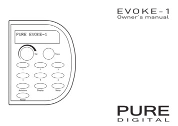
A medium-wave receiver1 A medium-wave receiverIntroductionLet us start off with something that is really quite simple and yet is capableof producing a sense of real satisfaction when complete – a real mediumwave (MW) radio receiver! It proves that receivers can be simple and, at thesame time, be useful and enjoyable to make. To minimise the confusion toabsolute beginners, no circuit diagram is given, only the constructionaldetails. The circuits will come later, when you have become accustomed tothe building process. In the true amateur spirit of ingenuity andinventiveness, the circuit is built on a terminal strip, the coil is wound ona toilet roll tube (as amateur MW coils have been for 100 years!), and thereceiver is mounted on a piece of wood.Putting it togetherStart by mounting the components on the terminal strip as shown in Figure1, carefully checking the position and value of each one. The threecapacitors are all the same, and so present no problem. They (and theresistors) may be connected either way round, unlike the two semiconductors (see later). The resistors are coded by means of coloured bands.You can refer to Chapter 7 if you have difficulty remembering the coloursand their values.Figure 1 Terminal strip –position of components1
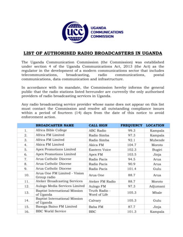
Radio and Electronics Cookbook1.2.3.4.Brown, Black, YellowGreen, Blue, BrownRed, Violet, BrownBrown, Black, Orange100 000 ohms560 ohms270 ohms10 000 ohms(R1, R5, R6)(R2)(R3)(R4)The integrated circuit (the ZN414Z) and the transistor (the BC184) must beconnected correctly. Check Figure 1 carefully before fitting each device.Now wind the coil. Most tubes are about 42 mm diameter and 110 mmlong. Don’t worry if your tube is slightly different; it shouldn’t matter. Maketwo holes, about 3 mm apart, about 40 mm from one end, as shown inFigure 2. Loop your enamelled wire into one hole and out of the other, anddraw about 100 mm through; loop this 100 mm through again, thusanchoring the wire firmly. Now wind on 80 turns, keeping the wire tightand the turns close together but not overlapping. After your 80th turn,make another two holes and anchor the wire in the same way as before.Again, leave about 100 mm free after anchoring. Using another piece ofenamelled wire (with 100 mm ends as before), loop one end through thesame two holes which contain the end anchor of the last winding, wind twoturns and anchor the end of this short winding using another pair of holes.Figure 2 shows the layout.Figure 2 The layout of theparts on the wooden base2
A medium-wave receiverWith some glass paper, remove the enamel from the ends of both piecesof wire which go through the same holes (i.e. the bottom of the large coiland the top of the small coil), then twist these bare ends together.Remove the enamel from the remaining ends of the coil. The coil is nowfinished!The baseboard can be any piece of wood about 150 mm square. Fix the coilnear the back edge using drawing pins and connect the wires from the coilsto the terminal strip as shown in Figure 2. Using short pieces of PVCinsulated wire (and with assistance if you have never soldered before),solder one piece across the two outer tags of the variable capacitor, shownby the dotted line in Figure 2, and then two longer pieces to the centre tagand one outside tag. Connect these to the terminal strip. Then solder twomore insulated wires on to the jack socket (into which you will plug yourcrystal earpiece), the other ends going to the terminal strip. The last twowires (one must be red) need to be soldered on to the battery box, theirother ends going to the terminal strip also. Make sure the red wire goes tothe positive terminal on the battery, and is connected to terminal 9. Theother connection to the battery goes to terminal 10.Attach the terminal strip to the baseboard with small screws or double-sidedsticky tape. The other parts can be mounted the same way.Listening is done ideally with the recommended crystal earpiece. Don’t betempted to use your Walkman earpieces; they are not the same and willnot perform anything like as well. The receiver should work without anextra aerial, but one can be attached to terminal 1 if necessary. A longpiece of wire mounted as high as possible is ideal. The Audio-frequencyAmplifier project will enable you to use a loudspeaker with your receiver,using the signal from the jack socket. No circuit modifications will beneeded!Parts listResistors: all 0.25R1, R5, R6R2R3R4CapacitorsC1, C2, C3watt, 5% tolerance10 kilohms (k )560 ohms270 ohms10 kilohms (k )100 nanofarads (nF)500 picofarads (pF)SemiconductorsZN414Z, BC1843
Radio and Electronics CookbookAdditional items12-way 2 A terminal strip22 metres of 28 SWG enamelled copper wireA few short pieces of coloured PVC-insulated wireCrystal earpiece3.5 mm jack socket1.5 V AA-size battery and boxToilet roll tubeDouble-sided sticky tape or selection of screwsTools requiredSmall screwdriver, soldering iron.2 An audio-frequencyamplifierIntroductionThis simple amplifier can be built by anyone who is able to solderreasonably well. It doesn’t require any setting up and, provided ourinstructions are followed exactly, will work very well. The circuit diagram isincluded for the benefit of our more advanced readers, but it is not neededin the construction process. Please practise your soldering before you start,and don’t use a printed circuit board (PCB) until you are confident that yoursoldering is up to scratch.The amplifier can be used with other projects; it will provide plenty ofsound from the MW Radio or from the Morse Sounder projects. It willusually be built into other pieces of equipment, so a box is not suppliedwith the kit. There is no reason why it shouldn’t be put into a box and usedas a general-purpose amplifier to help test other projects.The componentsBefore you start, you should check that you have all the components tohand. A list and some helpful hints are given below.4
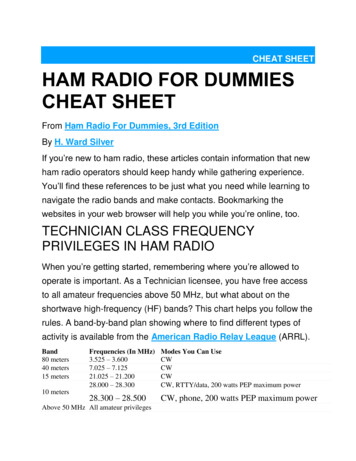
An audio-frequency amplifier1. PCB. The plain side is the component side and the soldered side is thetrack side. Figure 1 shows the track side full size. Make the PCB from thepattern given in Figure 1. Otherwise, build the circuit on a matrixboard.2. Three resistors. Locate the gold or silver band around the resistor, andturn the resistor until this band is to the right. There are three colouredbands at the left-hand end of the resistor. Find the resistor whose coloursare YELLOW, VIOLET, RED, and look at the resistor colour code chartwhich you will find in Chapter 7. From this, you will see that YELLOWindicates the value 4, VIOLET the value 7, and RED the value 2. Thefirst two colours represent real numbers, and the last value is the numberof zeros (noughts) which go after the two numbers. So, the value is 47with two zeros, i.e. 4700 ohms. In this way, the resistor colouredBROWN, GREY, BROWN has a value of 180 ohms, and the last one,BROWN, RED, GREEN, has a value of 1 200 000 ohms. The ohm (oftenwritten as the Greek letter omega ( )) is the unit of resistance. If you donot yet feel confident in identifying resistors by their colours, use theResistor Colour Codes given in Chapter 7.3. Four capacitors. The two small ‘beads’ are tantalum capacitors and will bemarked 4.7 F or 4 7, with a ‘ ’ above one lead. A tubular capacitor withwires coming from each end should be marked 220 F, with one endmarked ‘ ’ or ‘–’. This is called an axial capacitor because the wires lie onthe axis of the cylinder. This is in contrast to the final capacitor, where bothwires emerge from the same end. This is a radial capacitor, and will bemarked 47 F. Again, one lead will be marked ‘ ’ or ‘–’. Capacitorsmarked like this are said to be polarised, and it is vital that these are placedon the PCB the right way round, so take notice of those signs!4. Two diodes. These are tiny glass cylinders with a band around one end,and may be marked 1N4148; this is their type number. Like polarisedcapacitors, they must be put on the PCB the correct way round!Figure 1 The toil pattern ofthe PCB – looking from thetrack side5
Radio and Electronics Cookbook5. Three transistors. One should be a BC548 (or a BC182), the other twoshould be BC558 (or BC212).6. One volume control with internal switch.7. One loudspeaker. This is quite fragile – don’t let anything press againstthe cone.8. One PP3 battery clip with red and black leads.Putting it togetherLay the PCB on a flat, clean surface with the track side downwards. It isalways useful to compare the layout with the circuit diagram, given here inFigure 3. Although you can’t see it, the D-i-Y Radio sign should be at thetop. Compare the hole positions with those shown in Figure 2. Bend theresistor wires at right angles to their bodies so that they fit cleanly into theholes in the PCB. Push each resistor towards the board so that it lies flat onthe board. Then supporting each one, turn the board over and splay out thewires just enough to prevent the resistor falling out. Then, solder each wireto its pad on the PCB, and cut off the excess wire. When you have moreconfidence, you can cut of the excess wire before soldering; it often makesa tidier joint.Figure 2 Positions of thecomponents on the printedcircuit board (PCB)6
An audio-frequency amplifierFigure 3 The amplifier’scircuit diagramNow fit the four capacitors. Each must be connected the right way round,so look at each component, match it up with the diagram of Figure 2, bendits wires carefully and repeat the soldering process you performed with theresistors, making sure that the components are close to the board and not upon stilts! Fit the two diodes the correct way round, and solder then asquickly as you can – they don’t like to be fried!Mount the transistors about 5 mm above the PCB. Make sure the correcttransistors are in the correct places, and that the flats on the bodies matchup with those shown in Figure 2.Mount the volume control so that the spindle comes out from the front ofthe board. Use a piece of red insulated wire to the pad marked on the PCB,and a black piece to the pad marked –, and solder these to the tags on theback of the control, as shown in Figure 4. Connect the two leads from thebattery clip to the other tags on the switch; Figure 4 will help you. Finally,use two pieces of insulated wire about 100 mm long, twisted together, toconnect the loudspeaker to the PCB.Figure 4 Connections toswitch on back of VR17
Radio and Electronics CookbookBox clever!If you wish to put the amplifier into a box, there is no problem; almost anybox that is big enough will do. All that is needed is one hole big enough toaccept the bush of the volume control; the PCB will be supported by thevolume control. The prototype was not fitted into a box, but mounted on anodd piece of aluminium, bent into an L-shape and screwed on to a woodenbase. The loudspeaker was mounted on the aluminium panel by two smallpieces of aluminium with 3 mm holes drilled in them, which acted as clipsaround the edge of the speaker. Drill a few holes in the panel in the positionof the speaker to let the sound get out!Your input signal can be connected to the amplifier with two short pieces ofwire, but if the connection needs to be long, use screened cable, with thebraid connected as shown in Figure 2.If you decide to use a different loudspeaker, make sure that its impedance(the resistance value marked on the back of the magnet) is at least 35 ohms.Anything lower may damage TR2 and TR3, and will certainly run downyour battery very quickly. You will be surprised at the uses you can find forthis little amplifier!Parts listResistors: all 0.25 watt, 5% toleranceR1180 ohms ( )R24.7 kilohms (k )R31.2 megohms (M )VR125 kilohms (k ) log with DPST switchCapacitors: all rated at 25 V minimumC1, C24.7 microfarads ( F)C347 microfarads ( F)C4220 microfarads ( F)SemiconductorsTR1, TR3TR2D1, D2BC548 npnBC558 pnp1N4148Additional itemsPCBSpeaker 35 ohmsPP3 battery clip and battery8
A medium-wave receiver using a ferrite-rod aerial3 A medium-wave receiverusing a ferrite-rod aerialIntroductionThis design came from the Norfolk Amateur Radio Club, and enables you tobuild a simple Amplitude Modulation (AM) receiver for frequencies between600 kHz and 1600 kHz. It should take you around 2 hours to build, and canbe used with Walkman-type earpieces. Figure 1 shows the circuitdiagram.Figure 1 Circuit and blockdiagrams of the radioDescriptionThe whole circuit is built on a 50 mm by 50 mm printed circuit board (PCB)designed to fit on the inside of the lid of a plastic box, and is stuck thereusing sticky pads, the shaft of the variable capacitor going through a hole in9
Radio and Electronics CookbookFigure 2a The PCB, solder sideFigure 2b The PCB, component sidethe lid. Only two pairs of leads are soldered to the board – one pair goes tothe 1.5 V battery in its holder, and the other to the earphone socket. Figures2a and 2b show the printed circuit and the component layout double size forclarity. You are not obliged to build the circuit on a PCB.Building it1. Check and identify components. Tick the parts list.2. Carefully unwind the wire. Use paper to make an insulating tube (calleda ‘former’) around the centre of the ferrite rod and secure it withSellotape. Now, close-wind all the wire (leave no gaps between adjacentturns) around the paper former. Secure the winding with moreSellotape, leaving 50 mm of wire free at each end for connection to thecircuit. See Figure 3a.3. Solder in VC1.4. Solder in the integrated circuit holder. There is a notch in one end of theholder; this should face VC1. Solder also the wire link and thecapacitors. Be careful to avoid solder ‘bridges’ between adjacent trackson the PCB.5. Solder the battery leads. These must be connected properly – the redbattery lead to the (positive) area and the black lead to the –(negative) area.6. Strip bare 1 cm of insulation from the ends of two wires. Solder thembetween the PCB and the headphone socket (see Figure 3b). Use the endtabs on the socket. Using another pair of insulated wires connect theON/OFF switch to the PCB tabs shown in Figure 2b.10
A medium-wave receiver using a ferrite-rod aerialFigure 3 Details of coil andheadphone socket7. Fix the elastic band. This goes through the holes at the top of the PCB,with the ferrite rod being slipped through the two end loops. (Note:although the coating on the copper wire is designed to melt awayduring soldering, it is quite common for difficulty to be experienced inobtaining a good soldered joint; to be on the safe side, remove thecoating before soldering (with a small piece of sandpaper).) Carefullyplace the wire ends of the coil through the PCB just above VC1, andsolder on the track side.8. Fit IC1 into its holder. This should be done carefully, making sure thatall the pins are located above their respective clips before applying anypressure! Make sure also that the notch on the IC (as shown in Figure2b) matches the notch in the holder, and faces VC1.9. Put battery in its holder. Listen for some noise in the headphones asVC1 is rotated. Make sure the headphone plug is fully inserted into itssocket.10. Fix the working board to the lid. Use the sticky pads and apply gentlepressure. Fit the tuning knob, the ON/OFF switch and the earphonesocket.11. Test again. If all is still working, fit the lid screws and admire yourcompleted radio!11
Radio and Electronics CookbookParts listCapacitorsC1, C20.01 microfarad ( F)C3, C40.1 microfarad ( F)VC1500 picofarads (pF)SemiconductorIC1ZN416EAdditional itemsPlastic box (recommended size 76 64 50 mm internal)8-pin DIL socket for IC1Printed circuit boardTuning knob for VC1Wire link for PCB2 m of 30 SWG copper wire, self-fluxingPiece of paper 25 50 mm, to make the coil formerFerrite rod 70 mm long by 10 mm diameter, approximatelyBattery, AA size 1.5 V, with holder and attached wiresMiniature earphone socket (3.5 mm stereo jack)ON/OFF switch (push-button SPST latched or slide switch)4 off 100 mm insulated connecting wires, for jack socket andON/OFF switchPair Walkman-type earphonesElastic band, to attach ferrite rod to PCB4 off sticky pads for securing PCB to box lidKitsReady-made PCBs may be available from Alan J. Wright, G0KRU,Hewett School, Cecil Road, Norwich NR1 2PL.4 A simple electronic organIntroductionThis project has nothing to do with radio but, let’s admit it, any electronicsproject is good experience! Why not build this little organ – it will keep thechildren amused at least! It uses the popular NE555 integrated circuit,which contains a circuit which will periodically switch the voltage on theoutput pin between the supply voltage and zero. Just how frequently thisswitching occurs depends upon the components external to the integratedcircuit. If this switching occurs several hundred or thousand times a second,the change in voltage produced will generate a musical note whenconnected to a small loudspeaker. The circuit is shown in Figure 1.12
A simple electronic organFigure 1 Circuit diagramPutting it together(a) Using a PCB. The job is very simple. The placement of components onthe unsoldered side of the board is shown in Figure 2 and the design onthe copper track is illustrated in Figure 3. Put each component, in turn,on the board, making sure that it lies flat on the board with its tags orwires going cleanly through the holes provided for it; then, solder thewires to the board, cropping them before or after the soldering,Figure 2 Position of components on the printed circuit board (PCB)13
Radio and Electronics CookbookFigure 3 The connectionsdepending on your preference. If you choose to use a holder for yourintegrated circuit (highly recommended if your soldering is less thanperfect), make sure that the end with a notch in it faces R1 and R2, asshown in Figure 2. Solder the two leads to the speaker to the tabsmarked S (either way round), having looped them through the two holesto the right of the tabs in Figure 2. Looping them through the holes actsas a strain relief, ensuring that the soldered joints are not subjected topulling and bending as you move the wires about. Do the same with thebattery leads, the red lead going to the tab and the negative lead to the– tab (which also has one speaker lead already attached to it). Figure 4shows this in detail. Treat the loudspeaker with care – the cone is quitefragile and must not be touched.Figure 4 Battery plug andloudspeaker connections14
A simple electronic organ(b) Without a PCB. This is more difficult, and you may need to enlistsome help. Using some matrix board (such as Veroboard) is probablythe best way of replacing the PCB. You could arrange your circuit inexactly the same way as in the PCB in Figure 3, using wires to replacethe copper track.A simple ‘keyboard’The keyboard is a row of solder pins along the rear edge of the PCB, onefor each note covering the range shown in Figure 2. A flying lead with asmall spade on it is provided to touch any of the pins in turn, producingany one of ten different notes.TestingCheck first that each component is in the correct place. When insertingthe NE555 chip, first make sure that the end carrying the notch lies overthe end of the holder with the notch; then, make sure each pin of thechip lies directly above the hole into which it fits, before pressinggently to insert the chip into the socket. Make sure the battery connections are correct, and insert the battery into the clip. Nothing shouldhappen, except for a click from the loudspeaker; touching the spade onany of the pins should produce a coarse note from the speaker. If nothinghappens, check everything again; don’t assume that wires go where youthink they go!After you get the first note, all the others should work, too, but they willsound off-tune at first. The organ needs tuning up by adjusting the 10preset variable resistors P1 to P10. The approximate frequency to whicheach note should be tuned is given in Figure 2; if you can beg, borrow orsteal a frequency counter, setting up is easy. If you have a piano, theorgan can be tuned by comparison of the notes with those on the piano.The frequencies are given in Hertz (abbreviation Hz), and represent thenumber of times the IC switches on and off every second. If the soundcoming from the loudspeaker is too loud or very distorted, then tryputting an 330 resistor (colour code orange, orange, brown) in serieswith the loudspeaker. This is done by taking the resistor and cutting itsleads to about 5 mm; then, disconnect one speaker lead from the tab onthe PCB (it doesn’t matter which). Solder one end of the resistor to thevacated speaker tab, and the free speaker lead to the other end of theresistor. This will limit the volume of sound from the speaker, andlengthen the life of your battery. If it is still too loud, try a resistor of alarger value, or use a smaller resistor to make it louder.15
Radio and Electronics CookbookParts listResistors: all 0.25 watt, 5% toleranceR12.7 kilohms (k )R21 Megohm (M )P1–P5Preset resistor 100 kilohms (k )P6, P7Preset resistor 50 kilohms (k )P8Preset resistor 25 kilohms (k )P9, P10Preset resistor 10 kilohms (k )CapacitorC1100 nanofarads (nF) or 0.1 microfarad ( F)Integrated circuitIC1NE555 timer chipAdditional itemsSLoudspeaker 60 ohms (Maplin)1 off battery clip (for PP3 battery)1 off spade terminal12 off solder pins ‘Veropins’3 off 10 cm lengths of ‘hook-up’ wire(This article is based on projects originally designed by RadioScouting, Netherlands.)16
Experiments with the NE555 timer5 Experiments with theNE555 timerIntroductionSeveral of the projects in this book use the NE555 timer, an integratedcircuit which is at the heart of many circuits whose processes aredetermined by time intervals. Figure 1 shows the circuit diagram of anaudio oscillator using the 555. The timing voltages (governing thefrequency of oscillation) are produced by R1, R2 and C2; a voltage appearsat pin 3 which ‘switches’ at this frequency between zero and a voltage closeto the supply voltage, which in this case can be anywhere between 6 V and14 V. The output current, when applied through R3 to a small loudspeaker,produces an audible tone, provided that there is a DC path between the twotest leads.Figure 1 The circuitdiagram17
Radio and Electronics CookbookConstructionThe simplest way to mount the components is on a piece of matrix board(Veroboard), available from any of the good suppliers. The prototype of thiscircuit used the type of board with copper strips along the underside; thesestrips are used like the copper tracks on a PCB, to join components together.Firstly, cut the four strips between the positions of the pins of the IC socket,as shown in Figure 2. You can buy a tool for this purpose, but a small twistdrill (about 3 mm diameter) is just as good. Turn it between your fingers –if you use a drill you will end up with holes right through the board! Thensolder in the IC socket (with the notch in the position shown), followed bythe four links made with single-conductor insulated wire. Put in eachcomponent as shown, ensuring that C1 (an electrolytic or polarisedcapacitor) is connected correctly. When all the components have beensoldered in, take the 555 chip and lay it on its socket, with its own notchlying above that of the holder. Then, making sure that each pin lies directlyabove its corresponding socket, press down gently on the chip, with theboard supported on a flat surface.TestingConnect the circuit to a battery or small power supply, ensuring that thepositive and negative leads are the right way round. Always use red andblack leads here, then you are less likely to get it wrong! Switch on. NothingFigure 2 Veroboard layout.If you can read a circuitdiagram, the project can bebuilt using other methods18
Experiments with the NE555 timershould happen until you short together the two test leads, when thereshould be a note from the loudspeak
A breadboard 80cm CW transmitter 182. Contents vii 54. A 7-element low-pass filter for transmitters 186 . projects are backed up by small tutorials on the components and concepts . absolute beginners, no circuit diagram is given, only the constructional details. The cir