Transcription
ACERAC4 - AC6 - AC8Operator for sliding gatesInstructions and indicationsfor installation, use and maintenanceVers. 1.0-08/2004
GBGENERAL INFORMATIONINTENDED USEIt is strictly forbidden to copy or reproduce this instruction manualwithout written permission to do so by LIFE home integration andwill be subject to verification. Translation into other languages of all orpart of the manual is strictly forbidden without previous writtenauthorisation from LIFE home integration and will be subject toverification. All rights on this document are reserved. LIFE home integration will not accept responsibility for damage ormalfunctions caused by incorrect installation or improper use ofproducts and Users are therefore recommended to read this manualcarefully. LIFE home integration will not accept responsibility for damage ormalfunctions caused by the use of the operator together with thedevices of other manufacturers; such action will render the warrantyvoid LIFE home integration will not accept responsibility for damage orinjury caused by non-compliance with the installation, set up,maintenance and use indications contained in this manual and thesafety instructions described in the SAFETY INSTRUCTIONS ANDWARNINGS chapter. With the aim of improving its products, LIFE home integrationreserves the right to bring about alterations to them at any time, withoutgiving prior notice. This document conforms to the state of theautomation at which it is provided when released for sale.INFORMATION ON THE MANUFACTURERLIFE home integration is the manufacturer of the ACER operator(and will hereinafter be referred to as manufacturer) and the owner ofall rights concerning this document. The Manufacturer’s informationrequired by Machinery Directive 98/37/EC is given below: Manufacturer: LIFE home integration Address:Via I Maggio, 37 Telephone: 39 0422 809 254 Fax: 39 0422 809 250 http:www.homelife.it e-mail:info@homelife.it31043 FONTANELLE (TV) ItaliaThe identity plate bearing the information on the Manufacturer of theoperator is fixed to the control unit. The plate specifies the type anddate (month/year) of manufacture of the automation.For further information on technical or commercial issues andtechnician call-out and spares requests, Clients may contact theManufacturer or area representative from which the product waspurchased.2 ACER operators are designed for opening and closingresidential-type sliding gates only. Improper use or use ongates larger than those indicated in the TECHNICAL DATAchapter will be considered non-conform to the intended use.The Manufacturer declines all responsibility for improper use.The owner accepts full responsibility for improper use, whichwill result in the warranty being rendered void.Any usage differing from that described above is forbidden.The operator may not be installed or used in potentiallyexplosive environments.The Fitter must ensure that the environment in which theautomation is installed is conform to the operator ’stemperature range (see Technical Data chap.).The operator is not suitable for use on gates with built-in doorsunless the automation is prevented from functioning whenthe door is open.Motorised gates must conform to current European standards andDirectives, including EN 12604 and EN 12605.The operator may only be used when in perfect working order andin compliance with the intended use, in the awareness of safetyand hazard conditions and in observance with the instructions forinstallation and use.Any dysfunctions that may pose threats to safety must beeliminated immediately.The gate must be stable, properly hung and resistant to flexion (itmust not bend during opening and closure movements).The operator cannot compensate for faulty or incorrectly hunggates.The operator may not be used in environments prone to floodingDo not use the operator in environmental conditions characterisedby harsh atmospheric agents (e.g. Salty air).
GBINDEX8.2.4Condominium operating mode25INSTRUCTIONS AND INDICATIONS FOR INSTALLATION8.38.3.18.3.2ON/OFF selectorsBLACKOUT selectorPRE-FLASHING selector2525268.3.38.3.4LIGHTING IN PAUSE selectorPHOTOTEST selector26268.3.58.3.68.3.78.48.4.1PHOTO 1 selectorCLOSE AFTER PHOTO selectorOPENING RAM BLOW selectorProgressive functionsFORCE function26262627278.4.28.4.3PAUSE TIME functionCOURTESY LIGHT function27278.4.48.4.58.4.68.4.78.5DECELERATION IN CLOSING functionDECELERATION IN OPENING functionOBSTACLE DETECTION functionPEDESTRIAN OPENING functionFuses27272828288.5.18.5.2Frontal fuseCard fuses282899.19.2DIAGNOSTICSMalfunctions indicated by the control unitReplacing the frontal 4.3.455.15.25.35.45.4.1TECHNICAL DATAOperatorControl unitSAFETY INSTRUCTIONS AND WARNINGSGeneral safety instructions and warningsStorage instructions and warningsDESCRIPTION OF THE PRODUCTINSTALLATIONPreliminary checksInstructions and warnings for installationInstalling motor componentsPositioning and installing the base platePositioning and installing the operatorMounting the rackOperator releaseWIRING AND CONNECTIONSLIST OF ELECTRIC CABLESPreparing the electrics and mains connectionIntroducing the electric cables into the operatorControl unit connectionWiring diagram of line, light and various devices(right hand part of control unit) connection5.4.1.1 Description of line and light connections(230 Vac power supplies)5.4.1.2 Description of the connection of the devices5.4.1.3 Connecting photocells5.4.1.4 Indicator lights5.4.2 Wiring diagram for the connections on the lowerpart of the control unit5.4.2.1 Description of the connections on the lower partof the control unit5.4.3 Mounting the radio receiver6STARTING UP AND INITIAL CHECKS6.1Description of the keyboard6.2Initialisation6.3Initial adjustments and programming6.3.1 Identifying the direction of motion6.3.2 Identifying the travel6.3.3 Identifying the speed (obstacle detection settings)6.3.4 Measuring and adjusting Radio Control identificationRadio receiver memory modesRadio control settingsTotal erasure of the radio receiver memorySetting checksTESTING AND TRIAL RUNTestingFirst usageADVANCED ADJUSTMENTS AND SETTINGSKeyboardTotal reset of the cardResetting the gate travelPreset functions F1 and F2Dead man modeAutomatic modeSemi-automatic mode2-step automatic mode22222222222323232424242424242424248.2.34-step automatic mode25161617181920202021212121212122221011SPARE PARTSMANUFACTURER’S DECLARATION OF CECONFORMITYINSTRUCTIONS AND INDICATIONS FOR USE AND3032MAINTENANCESAFETY INSTRUCTIONS AND WARNINGSIndications and warnings for use323229Functions set on the radio controlFunctions set on the key selectorFlashing light functionsAutomation malfunction33333333Operator releaseMAINTENANCE3333Maintenance instructions and warningsCleaning the automationRoutine maintenance343434DEMOLITION AND DISPOSALLIST OF RESIDUAL RISKS PRESENT IN OPERATION34353
GB1TECHNICAL DATALIFE home integration reserves the right to vary the operator’stechnical features at any time and without giving prior notice, whilstmaintaining the same intended usage and functions.1.1OPERATORACERElectro-mechanical operator for sliding gates with built-in optic encoder and electroniccontrol unit.CENTRALE - 230 V a.c. 50HzAC4AC6AC8Mains power supplyV230 Vac 50 Hz230 Vac 50 Hz230 Vac 50 HzMotor power supplyV230 V a.c.230 V a.c.230 V F141416Built-in Genius control Typegreasegreaseoil C140140140Limit Switches2 electromechanicalOptic encoderyesSpeedm/min101010444%353535Nominal working timemin101010Operating temperature Cfrom -20 to 70Degree of protectionIP54Pinion tooth moduleDuty cicleMotor insulation classFMountingHorizontal using the base plate providedDimensions/weight170 (plate) x 342 x 288 (h) mm / 10 kgUsage in acid, saline or potentially explosive atmosphereMax gate weight4nokg400600800
GB1.2CONTROL UNITGENIUSMicroprocessor control units for 230 Vac motorwith encoder managementRG1Mains supply voltage230 Vac 50 HzMotor supply voltage230 Vac 50 HzADJUSTMENTSEXTRACTABLE CONNECTIONSCourtesy light time (sec)0-100MotoryesPause time (sec)0-100Encoder limit switch opening and closureyesnoOpening limit switchnoDeceleration in closing (% travel)0-20Closure limit switchnoDeceleration in opening (% travel)0-20Step by step impulsive - impulsiveyesObstacle detection an openingyesForcePartial/pedestrian opening (% travel)SETTINGSManual operation (dead man)yesStopyesSemi-automatic functionyesPhotocellyes4-step function (open - stop - close - stopyesPhotocell 1yes2-step function (open - close)yesPhotocell 2yesCondominium operating modeyes24 Vac (W max) gate open indicator light3Blackout (closed always for blackout)yes230 Vac (W max) flashing light40Pre-flashingyes24 Vac, Electrolock 15 VAyesFlashing during pauseyes230 Vac (W max) Courtesy light40Phototestyes24 Vac (mA max) Services200Photo also in opening (photo1)yesAerialyesClose after photoyesExtractable radio cardyesOpening ram blowyes5
GB2SAFETYINSTRUCTIONSWARNINGSAND 2.1 GENERAL SAFETY INSTRUCTIONS ANDWARNINGSThese general rules must always be respected during theinstallation, connection, testing, trial run, use andmaintenance of the automation.The Manufacturer declines responsibility for damage or injurycaused by non-conformity with the information suppliedconcerning installation, trial run, use and maintenancecontained in this manual, and the failure to observe the safetyinstructions given below.The installation, connection, testing, trial run and maintenanceof the operator must be performed by a COMPETENT PERSONaided and supervised by a PROFESSIONAL FITTER.Given the technical, procedural, regulation and legalimplications of the work, unauthorised fitters are notpermitted.Installation requires a practical and theoretical knowledge ofmechanics, electronics and electrics, and of sector laws andstandards.Amateur installation is strictly forbidden as it does not complywith current standards and laws and therefore does notguarantee the safe operation of the automation.Do not proceed with installation, connection and trial run inthe event of doubts or indecision of any kind.This manual must be read carefully and understood beforeinstalling the operator. If doubts arise during installation,contact a PROFESSIONAL FITTER or the MANUFACTURER.Do not perform adjustments and/or parameter memorisationbefore installation is complete and only if you have understoodthe procedures described in this manual.Only mount the operator on gates that are perfectly alignedwith the sliding tracks and are properly hung. A gate that isnot correctly aligned or hung can cause serious injury and/ordamage to the operator. 2.2 Fig. 16The Manufacturer declines all responsibility for damage and faultsto the operator caused by non-observance of the instructionscontained in this manual.Keep this manual in a safe and easily accessible place so that itcan be consulted rapidly when necessary.During installation, connection, trial run and usage of the operator,observe all applicable accident prevention and safety regulations.In the interests of safety and optimal functioning of the operator,only use original spares, accessories, devices and fasteningapparatus.Do not perform alterations on any operator device or component.This type of operation may cause malfunctions. The Manufacturerdeclines all responsibility for damage caused by products thathave been modified.The operator should not be used until the setting up proceduredescribed in the STARTING UP chapter has been performed.Should liquids penetrate inside the operator, disconnect theelectricity supply and contact the Manufacturer’s AssistanceService immediately; use of the operator in such conditions maycause hazard situations.In the case of faults or problems that cannot be resolved usingthe information contained in this manual, contact theManufacturer’s assistance service.STORAGEWARNINGSINSTRUCTIONSANDThe manufacturer declines all responsibility for damage andfaults to operator functioning caused by non-compliance withthe storage instructions given below.The operator must be stored in closed, dry places, at roomtemperatures of between –20 and 70 C.Keep the operator away from sources of heat and naked flames,which could damage it and cause malfunctions, fires or hazardsituations.Keep the operator in a horizontal position, but not resting on theground.
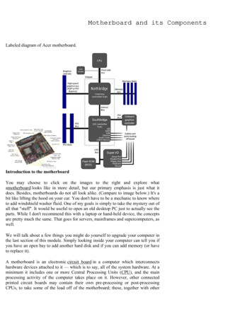
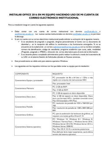
GB3DESCRIPTION OF THE PRODUCT4ACER is an electromechanical operator with a control unit, fitted witha key-operated release function in order to permit the gate to be movedmanually in the event of a power cut.INSTALLATIONBefore commencing installation we highly recommend readingthe instructions and warnings contained in this manual carefully(see the SAFETY INSTRUCTIONS AND WARNINGS Chap) andobserving the instructions it contains.Tab. 1: components and devices of a typical automation - fig. 1Pos. Description4.11.2.ACER operator with control unit.Radio receiver built-into control unit.3.4.5.Base plate.Pair of safety photocells (composed of a TX and an RX).Flashing light with aerial.6.7.89Key selector.Radio control.Right and left limit switch brackets.Photocell columns1011Mechanical doorstop.Rack.Before commencing installation, the following preliminary checks mustbe performed:1)The weight and dimensions of the gate must not exceed thelimits for use (see the TECHNICAL DATA chap.), if they exceedsuch limits, the operator may not be installed.2)The gate structure must be suitable for the installation of theoperator and conform to current standards.3)The gate’s movement in both opening and closure must beuniform, without points of greater resistance or friction.4)The gate must be properly hung and without risks of derailment,this can be checked by sliding the gate back and forth severaltimes.5)The gate must be hung flat, i.e. it must not move when left inany point of the sliding tracks. Ensure that the gate does notbend or deviate from its course during movement.6)The gate must be perfectly flat in to the plane to which the slidingtrack is fixed, in order to prevent irregular movement duringoperation.7)The limit switches must be sufficiently sturdy and there must beno risk of derailment should the gate collide with the limitswitches.8)The operator installation area must not be prone to flooding andtherefore it may not be installed in potholes, trenches, dips inthe ground, etc.9)The cement base on which the operator must be installed mustbe adequately solid and compact.Tab. 2: description of the contents of the ACER operator box ACER– fig. 2Pos. Description1.Cardboard box.2.ACER operator with control unit3.4.5.Base plate.Instruction Manual.Accessory box.6.7.8.2 limit switch brackets (right and left).2 release keys.4 screws and washers for fastening the operator to the basePRELIMINARY CHECKSplate.Fig. 27
GBINSTRUCTIONS AND WARNINGS FORINSTALLATION Before commencing installation read the SAFETYINSTRUCTIONS AND WARNINGS chapter carefully.The person who installs the operator is responsible forperforming risk analysis and regulating the automation’ssafety devices consequentially.Before commencing installation, check whether furtherdevices or materials are needed to complete the automationin order to suit the specific situation in which it will be used.It is strictly forbidden to motorise a gate that is not already efficientand secure as the automation cannot resolve faults caused byincorrect installation or poor maintenance of the gate.During installation, make constant reference to harmonisedstandards EN 12453 and EN12445.Ensure that the individual devices to be installed are suitable forthe automation that one intends to create, paying careful attentionto the points raised in the TECHNICAL DATA chapter. Do notproceed if even just one device is unsuitable for the intended use.Ensure that the place of installation is not prone to flooding, doesnot contain sources of heat or naked flames, fires or hazardsituations in general.During installation, protect automation components to preventliquids (e.g. rain) and/or foreign bodies (earth, gravel, etc)penetrating inside. 4.2 4.3INSTALLING MOTOR COMPONENTSThe area in which the operator is to be installed must be large enoughto perform maintenance work and manual opening ram blow. Checkthe overall dimensions by referring to figure 3.4.3.1 POSITIONING AND INSTALLING THE BASEPLATEa)Fig. 3Fig. 48Connect the control unit to a power supply line created incompliance with current regulations and earthed and fitted with apower supply selector.Wrapping materials must be disposed of in compliance with localregulations.Wear protective goggles when making holes for clamping.In the event of works at heights of over 2m from the ground, forexample for the installation of the indicator lamp or aerial, fittersmust be equipped with ladders, safety harnesses, protectivehelmet, and all other equipment required by law and the standardsgoverning this kind of work. Refer to Directive 89/655/EECamended by 2001/45/EC.For the installation of the operator base plate, observe thedistances given in fig. 4.
GBb)Refer to fig. 5 for matters concerning distances.f)Prepare the concrete mixture and pour it into the foundation dig,respecting the measurements given in fig. 6.ATTENTION: if the rack is already present, pay special attentionto comply with the measurements (fig. 5) in order to be able toinsert the pinion underneath the rack correctly.g)As soon as the concrete has been poured in, position the baseplate so that the tab (1 fig. 8) faces towards the gate, thenimmerge the L-shaped anchors into the concrete, threading theelectric cable tubes through the hole provided (2 fig. 8).Fig. 5c)d)Make a foundation large enough to contain the concrete basefor the operator’s base plate, referring to the distances given infigs. 4 and 5.Take the electric cable pipes to the installation site, leaving aprotrusion of 30 – 40 cm from the rest plane to be used forinstallation (fig. 6); plug them to prevent them from filling withdebris.Fig. 8ATTENTION: the base plate must not be completely immersed inthe concrete, but only up to the bottom edges; the sides mustremain outside (fig. 9).Fig. 6e)Fold the two anchorage “L” –shaped pieces in the base platedownwards through 90 (fig. 7) and plug the threaded holes toprevent them filling with debris.Fig. 7Fig. 99
GBh)Position the base plate flat using a spirit level in both directions(fig. 10).If the place in which the operator is to be installed already has afoundation for fixing the base plate, proceed as described below.a1)b1)c1)Position the base plate on the concrete base, respecting themeasurements shown in figures 4 and 5 and with the tab (1 fig.8) facing the gate.Check that the tubes for the electric cables are positionedcorrectly in relation to the base plate.Mark the centre of the holes for the clamping screws (fig. 12),shift the base plate and make the holes using a drill.Fig. 12Fig. 10i)After 2/3 days, when the concrete has solidified, proceed withthe installation procedure by cutting the electric cable tubes 1520mm above the base plate (fig. 11).d1)e1)Insert the screw anchors into the holes, position and fasten thebase plate to the concrete base using the four screws withwashers as indicated in figure 13.Use a spirit level placed in both directions (fig. 10) to ensure thatthe base plate is mounted flat, and fill in under corners ifnecessary.Fig. 11Fig. 1310
GB4.3.2 POSITIONINGOPERATORa)ANDINSTALLINGTHERemove the operator lid (1 fig. 14) and the cable gland hatch (2fig. 14) and slide off the clamping feet covers. (3 fig. 14).Fig. 16d)e)Make the vertical adjustments using the 4 dowels (fig. 15) and aspirit level.Make the horizontal adjustment and ensure that the operator isperfe
Manufacturer: LIFE home integration Address: Via I Maggio, 37 31043 FONTANELLE (TV) Italia Telephone: 39 0422 809 254 Fax: 39 0422 809 250 http: www.homelife.it e-mail: info@homelife.it The identity plate bearing the information on the Manufacturer of the operator is fixed to the control unit. The plate specifies the .