Transcription
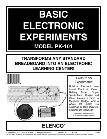
BASICELECTRONICEXPERIMENTSMODEL PK-101TRANSFORMS ANY STANDARDBREADBOARD INTO AN ELECTRONICLEARNING CENTER!Perform 50Experiments!Build an Electronic Keyboard, Electronic Kazoo,Battery Tester, FingerTouch Lamp, Burglar andWater Alarms, a Siren, aMagnetic Bridge, and awhole lot more! Nosoldering or tools required,all parts are included!(Requires a breadboard anda 9V battery or power supply.)ELENCOCopyright 2011, 1999 by ELENCO All rights reserved. Revised 2011REV-FNo part of this book shall be reproduced by any means; electronic, photocopying, or otherwise without written permission from the publisher.753064
In this booklet you will learn: The basic principles of electronics. How to build circuits using a breadboard. How all of the basic electronic components work and how to read their values. How to read electronic schematics. How to design and troubleshoot basic electronic circuits. How to change the performance of electronic circuits by changing component values within the circuit.TABLE OF CONTENTSParts ListPage 3Answers to Quizzes3Introduction to Basic Components4Experiment #1: The Light Bulb8More About Resistors10Experiment #2: Brightness Control12Experiment #3: Resistors in Series13Experiment #4: Parallel Pipes14Experiment #5: Comparison of Parallel Currents15Experiment #6: Combined Circuit16Experiment #7: Water Detector17Introduction to Capacitors18Experiment #8: Slow Light Bulb20Experiment #9: Small Dominates Large21Experiment #10: Large Dominates Small22Experiment #11: Make Your Own Battery23Test Your Knowledge #124Introduction to Diodes24Experiment #12: One - Way Current25Experiment #13: One - Way Light Bulbs26Introduction to Transistors27Experiment #14: The Electronic Switch28Experiment #15: The Current Amplifier28Experiment #16: The Substitute29Experiment #17: Standard Transistor Biasing Circuit 30Experiment #18: Very Slow Light Bulb31Experiment #19: The Darlington32Experiment #20: The Two Finger Touch Lamp32Experiment #21: The One Finger Touch Lamp33Experiment #22: The Voltmeter34Experiment #23: 1.5 Volt Battery Tester36Experiment #24: 9 Volt Battery Tester37Experiment #25: The Battery Immunizer38Experiment #26: The Anti-Capacitor39Introduction to Inductors and TransformersTest Your Knowledge #2Experiment #27: The Magnetic BridgeExperiment #28: The LighthouseExperiment #29: Electronic SoundExperiment #30: The AlarmExperiment #31: Morse CodeExperiment #32: SirenExperiment #33: Electronic RainExperiment #34: The Space GunExperiment #35: Electronic NoisemakerExperiment #36: Drawing ResistorsExperiment #37: Electronic KazooExperiment #38: Electronic KeyboardExperiment #39: Fun with WaterExperiment #40: Blinking LightsExperiment #41: Noisy BlinkerExperiment #42: One ShotExperiment #43: Alarm With Shut - Off TimerExperiment #44: The Flip - FlopExperiment #45: Finger Touch Lamp With MemoryExperiment #46: This OR ThatExperiment #47: Neither This NOR ThatExperiment #48: This AND ThatExperiment #49: Audio NAND, ANDExperiment #50: Logic CombinationTest Your Knowledge #3Troubleshooting GuideDefinition of TermsTHE EXPERIMENTS IN THIS BOOKLET REQUIRE A BREADBOARD ORCAN BE DONE ON THE ELENCO XK-150, XK-550, OR XK-700 626364656667686869
PARTS LISTQuantityPart 0098590102-Description470Ω Resistor, 0.25W1kΩ Resistor, 0.25W3.3kΩ Resistor, 0.25W10kΩ Resistor, 0.25W33kΩ Resistor, 0.25W100kΩ Resistor, 0.25W1MΩ Resistor, 0.25W50kΩ Variable Resistor, lay-down, with dial0.005μF Disc Capacitor0.047μF Disc Capacitor10μF Electrolytic Capacitor100μF Electrolytic CapacitorDiode, 1N4148Transistor, NPN, 2N3904Light Emitting Diodes (LEDs)TransformerSwitch, push-button9V Battery ClipSpeaker, 8Ω, 0.25 Watt, with wires addedWires BagQUIZ ANSWERSFirst Quiz: 1. electrons; 2. short; 3. battery; 4. increase; 5. insulators, conductors; 6. decreases, increases; 7. decreases;8. voltage; 9. alternating, direct; 10. increases, decreases.Second Quiz: 1. reverse; 2. LEDs; 3. amplifier; 4. integrated; 5. saturated; 6. alternating, direct; 7. decreases, increases;8. magnetic; 9. increases; 10. twiceThird Quiz: 1. feedback; 2. air, pressure; 3. decreases; 4. OR; 5. NAND3
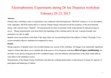
INTRODUCTION TO BASIC COMPONENTSWelcome to the exciting world of Electronics! Before starting the first experiment, let’s learn about some of the basicelectronic components. Electricity is a flow of sub-atomic (very, very, very, small) particles, called electrons. Theelectrons move from atom to atom when an electrical charge is applied across the material. Electronics will be easier tounderstand if you think of the flow of electricity through circuits as water flowing through pipes (this will be referred to asthe water pipe analogy).Wires: Wires can be thought of as large, smooth pipes that allow water to pass through easily. Wires are made of metals,usually copper, that offer very low resistance to the flow of electricity. When wires from different parts of a circuit connectaccidentally we have a short circuit or simply a short. You probably know from the movies that this usually means trouble.You must always make sure that the metal from different wires never touches except at springs where the wires areconnecting to each other. The electric current, expressed in amperes (A, named after Andre Ampere who studied therelationship between electricity and magnetism) or milliamps (mA, 1/1000 of an ampere), is a measure of how fastelectrons are flowing in a wire just as a water current describes how fast water is flowing in a pipe.PIPEWIREBatteries and Generators: To make water flow through a pipe we need a pump. To make electricity flow through wires,we use a battery or a generator to create an electrical charge across the wires. A battery does this by using a chemicalreaction and has the advantage of being simple, small, and portable. If you move a magnet near a wire then electricity willflow in the wire. This is done in a generator. The electric power companies have enormous generators driven by steam orwater pressure to produce electricity for your home.The voltage, expressed in volts (V, and named after Alessandro Volta who invented the battery in 1800), is a measure ofhow strong the electric charge from your battery or generator is, similar to the water pressure. Your PK-101 may be usedwith either a 9V battery or the adjustable power supply that is part of the XK-150, XK-550, and XK-700 Trainers. A powersupply converts the electricity from your electric company into a simple form that can be used in your PK-101. If using thepower supply, then adjust it for 9V. (This manual will usually refer to the battery, this is also meant to refer to the 9V powersupply if you are using that instead). Notice the “ ” and “–” signs on the battery. These indicate which direction the batterywill “pump” the electricity, similarly to how a water pump can only pump water in one direction. The 0V or “–” side of thebattery is often referred to as “ground”. Notice that just to the right of the battery pictured below is a symbol, the samesymbol you see next to the battery holder. Engineers are not very good at drawing pictures of their parts, so whenengineers draw pictures of their circuits they use symbols like this to represent them. It also takes less time to draw andtakes up less space on the page. Note that wires are represented simply by lines on the page.WATER PUMPBATTERYSymbol for BATTERY9VThe Switch: Since you don’t want to waste water when you are not using it, you have a faucet or valve to turn the wateron and off. Similarly, you use a switch to turn the electricity on and off in your circuit. A switch connects (the “closed” or“on” position) or disconnects (the “open” or “off” position) the wires in your circuit. As with the battery, the switch isrepresented by a symbol, shown below on the right.VALVESWITCHYou have been given one of the two above switches.4Symbol for SWITCH
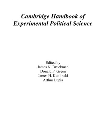
The Resistor: Why is the water pipe that goes to your kitchen faucet smaller than the one that comes to your house fromthe water company? And why is it much smaller than the main water line that supplies water to your entire town? Becauseyou don’t need so much water. The pipe size limits the water flow to what you actually need. Electricity works in a similarmanner, except that wires have so little resistance that they would have to be very, very thin to limit the flow of electricity.They would be hard to handle and break easily. But the water flow through a large pipe could also be limited by filling asection of the pipe with rocks (a thin screen would keep the rocks from falling over), which would slow the flow of water butnot stop it. Resistors are like rocks for electricity, they control how much electric current flows. The resistance, expressedin ohms (Ω, named after George Ohm), kilohms (kΩ, 1,000 ohms), or megohms (MΩ, 1,000,000 ohms) is a measure ofhow much a resistor resists the flow of electricity. To increase the water flow through a pipe you can increase the waterpressure or use less rocks. To increase the electric current in a circuit you can increase the voltage or use a lower valueresistor (this will be demonstrated in a moment). The symbol for the resistor is shown on the right.ROCKS IN THE PIPERESISTORSymbol for RESISTOR“LEADS” for connectingYour Breadboard: Breadboards are used for mounting electronic components and to make connecting them togethereasy, and are similar to the printed circuits boards used in most electronic devices. Breadboards make it easy to add andremove components. Your breadboard has 830 holes arranged into rows and columns (some models may have more orless holes but will be arranged the same way):BREADBOARD5
The holes are connected together as follows: There are many columns of 5 holes each. The 5 holes within each column are electrically connected together, but thecolumns are not electrically connected to each other. This makes 126 columns of 5 holes each. Note that “electricallyconnected together” means that there is a wire within the breadboard connecting the 5 holes. All holes in the rows marked with a blue “–” or a red “ ” are electrically connected together, but none of these rows areelectrically connected to each other. This makes 6 rows of 100 holes. The red “ ” holes will usually be used for your “ ”battery or power supply connections and the blue “–” holes will usually be used for your ground (“–” battery or powersupply) connections.BREADBOARD CONNECTIONSInserting Parts into the Breadboard: To insert components into the breadboard, keep their pins straight and gently pushinto the holes. If the pins get bent and become difficult to insert, they can be straightened with a pliers. Always make surecomponents do not touch each other.INSERTING PARTSElectrolytic capacitors have a positiveand a negative electrode. The negativelead is indicated on the packaging by astripe with minus signs and possiblyarrowheads.Warning:If the capacitor isconnected withincorrect polarity,it may heat up andeither leak, orcause thecapacitor toexplode.PolarityMarking6
After using your kit for a while, some of the wire ends may break off. If so, you should remove about 3/8 inch of insulationfrom the broken end with a wire stripper or scissors.Before You Begin: The rows of the breadboard are marked with letters (some rows are marked “ ” and “–”) and thecolumns are marked by numbers, this allows each hole to be identified individually. We will use this notation to smoothlyguide you through the experiments. Depending on the size of your breadboard, several sets of rows may be marked withthe same letter, but only a portion of the overall breadboard will be used so this will not be a problem. The row and columnnumbers will be expressed as a row/column number. For example, a connection at row b, column 26 will be called holeb26. And a connection at row , column 3 will be called hole ( )3. Some examples of this are shown below:IDENTIFYING HOLE LOCATIONScolumn 3row ( )hole h6hole e15row bhole (-)7column 267
EXPERIMENT #1: The Light BulbFirst, decide if you will use a 9V battery (alkaline is best) or the adjustable power supply that is part of the XK-150, XK-550,and XK-700 Trainers. If using a battery then snap it into its clip. Always remove the battery from its clip if you won’t be usingyour PK-101 for a while. Insert the red wire from the battery clip into hole j4 and the black wire into hole (–)3.12If using the adjustable power supply then turn it on and adjust it for 9V. Connect a wire from the positive adjustable voltageoutput to hole j4 and another wire from the power supply negative output (ground) to hole (–)3.Let’s introduce another component, the LED (light emitting diode). It is shown below, with its symbol. We’ll explain what itdoes in just a few moments.LEDSymbol for LEDFlatNow insert the components for this circuit into your breadboard according to the list below (the first item is for thebattery/power supply which you already did above), which we’ll call the Wiring Checklist. When you’re finished your wiringshould look like the diagram shown at right:WIRING DIAGRAMParts Needed: a 9V battery or power supply one Switch one 10kΩ resistor(marked brown-black-orange-gold, in that order) one LED 2 wiresPOWERSUPPLY 9VRESISTOR0V (GROUND)Wiring Checklist:LED(symbol shows flatside is on right)10kΩ(RED)Insert red battery wire or positive power supply intohole j4 and black battery wire or negative powersupply (ground) into hole (–)3.Insert switch into holes f4 and f5.Insert the 10kΩ resistor into holes j5 and j9.Insert the LED into holes g20 and g21. NOTE: The“flat” side of the LED (as shown on the pictureabove, and usually the shorter wire) goes into g21.Insert a short wire between holes h9 and j20.9VBATTERYInsert a short wire between holes f21 and (–)21.SWITCH(BLACK)Be sure all your wires are securely in place and notloose. Also make sure the metal into each hole isnot touching any other metal, including other partsof the same component.8WIRES
The Wiring Checklist and Wiring Diagram showyou ONE way of connecting the circuitcomponents using your breadboard. There aremany other ways that are also correct. Theimportant thing is that the electrical connectionsare as shown in the schematic (see below).Example of Inserting the ResistorPress the switch and the LED lights up, and turns off when you release the switch. The LED converts electrical energyinto light, like the light bulbs in your home. You can also think of an LED as being like a simple water meter, since as theelectric current increases in a wire the LED becomes brighter. It is shown again here, with its symbol.WATER METERLEDSymbol for LEDFlatTake a look at the water diagram that follows. It shows the flow of water from the pump through the faucet, the small pipe,the water meter, the large pipes, and back to the pump. Now compare it to the electrical diagram next to it, called aschematic. Schematics are the “maps” for electronic circuits and are used by all electronic designers and technicians oneverything from your PK-101 to the most advanced supercomputers. They show the flow of electricity from the batterythrough the switch, the resistor, the LED, the wires, and back to the battery. They also use the symbols for the battery,switch, resistor, and LED that we talked about. Notice how small and simple the schematic looks compared to the waterdiagram; that is why we use it.Now you will see how changing the resistance in the circuit increases the current through it. Press the switch again andobserve the brightness of the LED. Now remove the 10kΩ resistor and replace it with a 1kΩ resistor (marked brown-blackred-gold, in that order) in the same holes (j5 and j9). Press the switch. The LED is brighter now, do you understand why?We are using a lower resistance (less rocks), so there is more electrical current flowing (more water flows), so the LED isbrighter. Now replace the 1kΩ resistor with the 100kΩ resistor (marked brown-black-red-gold, in that order) and press theswitch again. The LED will be on but will be very dim (this will be easier to see if you wrap your hand near the LED to keepthe room lights from shining on it).Well done! You’ve just built YOUR first electronic circuit!9
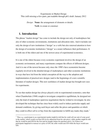
MORE ABOUT RESISTORSOhm’s Law: You just observed that when you have less resistance in the circuit, more current flows (making the LEDbrighter). The relationship between voltage, current, and resistance is known as Ohm’s Law (after George Ohm whodiscovered it in 1828):VoltageCurrent ResistanceResistance: Just what is Resistance? Take your hands and rub them together very fast. Your hands should feel warm.The friction between your hands converts your effort into heat. Resistance is the electrical friction between an electriccurrent and the material it is flowing through; it is the loss of energy from electrons as they move between atoms of thematerial. Resistors are made using carbon and can be constructed with different resistive values, such as the seven partsincluded in your PK-101. If a large amount of current is passed through a resistor then it will become warm due to theelectrical friction. Light bulbs use a small piece of a highly resistive material called tungsten. Enough current is passedthrough this tungsten to heat it until it glows white hot, producing light. Metal wires have some electrical resistance, but itis very low (less than 1Ω per foot) and can be ignored in almost all circuits. Materials such as metals which have lowresistance are called conductors. Materials such as paper, plastic, and air have extremely high values of resistance andare called insulators.Resistor Color Code: You are probably wondering what the colored bands on the resistors mean. They are the methodfor marking the value of resistance on the part. The first ring represents the first digit of the resistor’s value. The secondring represents the second digit of the resistor’s value. The third ring tells you the power of ten to multiply by, (or the numberof zeros to add). The final and fourth ring represents the construction tolerance. Most resistors have a gold band for a 5%tolerance. This means the value of the resistor is guaranteed to be within 5% of the value marked. The colors below areused to represent the numbers 0 through YWHITEVALUE0123456789Example of Color CodeREDVIOLETORANGEGOLD27 X 10,000 27,000 Ω, with 5% ToleranceUse the color code to check the values of the seven resistors included in your PK-101, and compare to the list below:YELLOW - VIOLET - BROWN - GOLD is 470 Ω with 5% toleranceBROWN - BLACK - RED - GOLD is 1,000 Ω (or 1 kΩ) with 5% toleranceORANGE - ORANGE - RED - GOLD is 3,300 Ω (or 3.3 kΩ) with 5% toleranceBROWN - BLACK - ORANGE - GOLD is 10,000 Ω (or 10 kΩ) with 5% toleranceORANGE - ORANGE - ORANGE - GOLD is 33,000 Ω (or 33 kΩ) with 5% toleranceBROWN - BLACK - YELLOW - GOLD is 100,000 Ω (or 100 kΩ) with 5% toleranceBROWN - BLACK - GREEN - GOLD is 1,000,000 Ω (or 1 MΩ) with 5% tolerance10
The Variable Resistor: We talked about how a switch is used to turn the electricity on and off just like a valve is used toturn the water on and off. But there are many times when you want some water but don’t need all that the pipe can deliver,so you control the water by adjusting an opening in the pipe with a faucet. Unfortunately, you can’t adjust the thickness ofan already thin wire. But you could also control the water flow by forcing the water through an adjustable length of rocks,as in the rock arm shown below.ROCKARMIn electronics we use a variable resistor. This is a normal resistor (50kΩ in your PK-101) with an additional arm contactthat can move along the resistive material and tap off the desired resistance.VARIABLE RESISTORINSULATING BASE MATERIALWIPER CONTACTTHIN LAYER OFRESISTIVE MATERIALMOVABLEARMSTATIONARY CONTACTLEADSThe dial on the variable resistor moves the arm contact and sets the resistance between the left and center pins. Theremaining resistance of the part is between the center and right pins. For example, when the dial is turned fully to the left,there is minimal resistance between the left and center pins (usually 0Ω) and maximum resistance between the center andright pins. The resistance between the left and right pins will always be the total resistance, (50kΩ for your part).VARIABLE RESISTORCENTER PINSymbol for VARIABLE RESISTORLEFT PINRIGHT PINNow let’s demonstrate how this works.11
EXPERIMENT #2: THE BRIGHTNESS CONTROLRemove the 10kΩ resistor used in Experiment #1; the other parts are used here. Insert the new parts according to theWiring Checklist below. Press the switch and the LED lights up (it may be dim). Now hold the switch closed with one handand turn the dial on the variable resistor with the other. When the dial is turned to the left, the resistance in the circuit islow and the LED is bright because a large current flows. As you turn the dial to the right the resistance increases and theLED will become dim, just as forcing the water through a section of rocks would slow the water flow and lower the readingon your water meter.You may be wondering what the 1kΩ resistor is doing in the circuit. If you set the dial on the variable resistor for minimumresistance (0Ω) then Ohm’s Law tells us the current will be very large - and it might damage the LED (think of this as avery powerful water pump overloading a water meter). So the 1kΩ was put in to limit the current while having little effecton the brightness of the LED.Now remove the wire from c14 and connect it to c16. Do you know what will happen now? Close the switch and you willsee that as you turn the dial from the left to the right the LED goes from very dim to very bright (the opposite of whenconnected to c14), because you are decreasing the resistance between the center and right pins.Now remove the 1kΩ resistor from hole j15 and insert it into hole c14 (the other end stays in j5). What do you think willhappen? Close the switch and turn the dial on the variable resistor. The LED is dim and turning the resistor dial won’tmake it any brighter. As discussed above, the resistance between the left and right pins is always 50kΩ and the part actsjust like one of the other resistors in your PK-101.Variable resistors like this one are used in the light dimmers youmay have in your house, and are also used to control the volumein your radio, your TV, and many electronic devices.Parts Needed: a 9V battery or power supply Switch one 1kΩ resistor (marked brown-black-red-gold) 50kΩ variable resistor one LED 2 wiresWiring Checklist (experiment):WIRING DIAGRAMPOWERSUPPLY 9VLED0VRESISTOR50kΩVARIABLERESISTOR(symbol showsflat side is onright)(RED)1kΩindicates same position as lastInsert red battery wire or positive power supply into hole j4and black battery wire or negative power supply (ground) intohole (–)3.Insert switch into holes f4 and f5.Insert the LED into holes g20 and g21 (“flat” side goes into g21).Insert a short wire between holes f21 and (–)21.Insert the 1kΩ resistor into holes j5 and j15.Insert the 50kΩ variable resistor into holes e14, g15, and e16.It may be a tight fit, carefully press it in slowly.Insert a short wire between holes c14 and j20.9VBATTERYSWITCH(BLACK)Be sure all your wires are securely in place and not loose. Alsomake sure the metal into each hole is not touching anyother metal, including other parts of the same component.SCHEMATICWATER DIAGRAM12WIRES
EXPERIMENT #3: RESISTORS IN SERIESRemove the resistors used in Experiment #2; the other parts are used here. Insert the new parts according to the WiringChecklist and press the switch. The LED is on but is very dim (this will be easier to see if you wrap your hand near theLED to keep the room lights from shining on it). Take a look at the schematic. There is a low 3.3kΩ resistor and a high100kΩ resistor in series (one after another). Since the LED is dimly lit, we know that the larger 100kΩ must be controllingthe current. You can think of this as where two sections of the pipe are filled with rock, if one section is much longer thanthe other then it controls the water flow. If you had several rock sections of different lengths then it is easy to see that thesewould add together as if they were one longer section. The total length is what matters, not how many sections the rockis split into. The same is true in electronics - resistors in series add together to increase the total resistance for thecircuit. (In our circuit the 3.3kΩ and 100kΩ resistors add up to 103.3kΩ).To demonstrate this, remove the 100kΩ resistor and insert the 10kΩ in the same holes, press the switch; the LED shouldbe easy to see now (total resistance is now only 13.3kΩ). Next, remove the 10kΩ resistor and replace it with the 1kΩ. TheLED is now bright, but not as bright as when you used the 1kΩ in Experiment #1. Why? Because now the 3.3kΩ is thelarger resistor (total resistance is 4.3kΩ).Also, in Experiment #2 you saw how the 1kΩ resistor would dominate the circuit when the variable resistor was set for 0Ωand how the variable resistor would dominate when set for 50kΩ.Wiring Checklist ( indicates same position aslast experiment):Insert red battery wire or positive power supply intohole j4 and black battery wire or negative powersupply (ground) into hole (–)3.Insert switch into holes f4 and f5.Insert the LED into holes g20 and g21 (“flat” sidegoes into g21).Insert a short wire between holes f21 and (–)21.Insert the 3.3kΩ resistor into holes i5 and i12.Insert the 100kΩ resistor into holes j12 and j20(avoid touching other components).WIRING DIAGRAMPOWERSUPPLYLED 9V0VRESISTORS3.3kΩ(symbol shows flatside is on right)100kΩ(RED)Parts Needed: a 9V battery or power supply Switch one 1kΩ resistor (brown-black-red-gold) one 3.3kΩ resistor (orange-orange-red-gold) one 10kΩ resistor (brown-black-orange-gold) one 100kΩ resistor (brown-black-yellow-gold) one LED 1 wire9VBATTERYSWITCH(BLACK)WATER DIAGRAMSCHEMATIC13WIRE
EXPERIMENT #4: PARALLEL PIPESRemove the resistors used in Experiment #3; the other parts are used here. Insert the new parts according to the WiringChecklist. Take a look at the schematic. There is a low 3.3kΩ resistor and a high 100kΩ resistor in parallel (connectedbetween the same points in the circuit). How bright do you think the LED will be? Press the switch and see if you are right.The LED is bright, so most of the current must be flowing through the smaller 3.3kΩ resistor. This makes perfect sensewhen we look at the water diagram, with most of the water flowing through the pipe with less rocks. In general, the morewater pipes (or resistors) there are in parallel, the lower the total resistance is and the more water (or current) will flow.The relationship is more complicated than for resistors in series and is given here for advanced students:RParallelR1 x R2 R1 R2For two 10kΩ resistors in parallel, the result would be 5kΩ. The 3.3kΩ and 100kΩ in parallel in our circuit now give thesame LED brightness as a single 3.2kΩ resistor.To demonstrate this, remove the 100kΩ resistor and replace it with the 10kΩ (in the same holes); press the switch and theLED should be just as bright. The total resistance is now only 2.5kΩ, but your eyes probably won’t notice much differencein LED brightness. Now remove the 10kΩ and replace it with the 1kΩ; press the switch. The total resistance is now only770Ω, so the LED should now be much brighter.Parts Needed: a 9V battery or power supply Switch one 1kΩ resistor (brown-black-red-gold) one 3.3kΩ resistor (orange-orange-red-gold) one 10kΩ resistor (brown-black-orange-gold) one 100kΩ resistor (brown-black-yellow-gold) one LED 2 wiresWiring Checklist ( indicates same position as lastexperiment):Insert red battery wire or positive power supply (P. S.) into j4 andblack battery wire or negative power supply (ground) into (–)3.Insert switch into f4 and f5.Insert the LED into g20 and g21 (“flat” side goes into g21).Insert a short wire between f21 and (–)21.Insert the 3.3kΩ resistor into i5 and i12.Insert the 100kΩ resistor into j5 and j12.Insert a short wire between h12 and j20.WIRING DIAGRAMNote: From now on there will be less description for frequently used parts.100KΩ3.3KΩ9VBATTERYor POWERSUPPLY 9V0V14
EXPERIMENT 5: COMPARISON OF PARALLEL CURRENTSSince we have two resistors in parallel and a second LED that is not being used, let’s modify the last circuit to match theschematic below. It’s basically the same circuit but instead of just parallel resistors there are parallel resistor-LED circuits.Remove the resistors used in Experiment #4; the other parts are used here. Insert the new parts according to the WiringChecklist. Replace the 100kΩ resistor with several values as before (such as 1kΩ, 10kΩ, and others if you wish), pressingthe switch and observing the LEDs each time. The brightness of the right LED will not change, but the brightness of theleft LED will depend on the resistor value you placed in series with it.Parts Needed: a 9V battery or power supply Switch one 3.3kΩ resistor (orange-orange-red-gold) one 100kΩ resistor (brown-black-yellow-gold) 2 LEDs 4 wiresWiring Checklist (þ indicates same position as last experiment):Insert red battery wire or positive P. S. into j4 and black battery wire or negative P. S. (ground) into (–)3.Insert switch into f4 and f5. The switch may be a tight fit, carefully press it in slowly.Insert an LED into g20 and g21 (“flat” side goes into g21).Insert a short wire between f21 and (–)21.Insert the 100kΩ resistor into j5 and j12.Insert a short wire between h12 and j20.Insert the 3.3kΩ resistor into i5 and j10.Insert a short wire between g10 and j23.Insert an LED into g23 and g24 (“flat” side goes into g24).Insert a short wire between f24 and (–)24. 9V1
† How to design and troubleshoot basic electronic circuits. † How to change the performance of electronic circuits by changing component values within the circuit. THE EXPERIMENTS IN THIS BOOKLET REQUIRE A BREADBOARD OR CAN BE