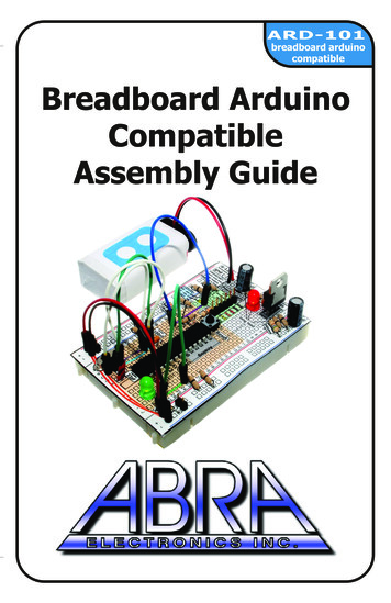
Transcription
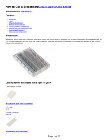
BreadboardIn this tutorial we will cover breadboards step by step and get deep into very detail so you can learn thefundamental principles involved, from basics to advanced, and how to use them to build electronicsprojects with the aid of examples and short videos. At the end of this tutorial, you will have a chance totest all areas of your knowledge through a quiz.In this tutorialIntroduction What is a breadboard?What’s the reason behind the name?Types of breadboardsBreadboard layout Breadboard terminologyWhat’s inside the breadboard?How to use a breadboard Which components are best to use with breadboards? An example of building a circuit using a breadboardCommon mistakesTips and tricksSafety instructionsQuizAnswers to the quiz
IntroductionWhat is a breadboard?The breadboard or solderless breadboard is the most popular tool used for prototyping (buildingtemporary electronic circuits and testing them before the final version is permanently designed) withoutany need for soldering.You can use it as an independent circuit to create your project, or it can be used as an auxiliary part of amain circuit such as Arduino or Raspberry pi.The breadboard has a user-friendly construction and quite a safe layout, which make it an important stepfor newcomers to electronics who wish to test their ideas in quick experiments. However, you can use thebreadboard to build all types of electronics projects, starting from very basic circuits to the mostcomplicated robotics.What’s the reason behind the name “breadboard”?You may ask “what does a breadboard have to do with electronics?” And if your imagination pictures afresh loaf on a piece of wood, then you are not far from guessing where the name comes from.The name “breadboard” goes way back to the days when people would literally use a piece of wood onwhich they sliced bread, in order to construct electronic circuits. They used nails and wires to connect upthe components. Nowadays, the new generation of “breadboard” is made from a rectangular piece ofplastic, but we still refer to them by the name “breadboard.”Breadboard circuit in the pastBreadboard circuit today
Types of breadboardBreadboards come in various brands and sizes to suit the requirements of the electronic circuit.Nevertheless, all breadboards share the same fundamentals and ideas.Here are some types of a standard breadboard:1. Full-size2. Half-size3. MiniFull-sizeHalf-sizeMiniMoreover, there are different colors of breadboards (white, blue, red, green, yellow, transparent).
Breadboard layoutWhat is the breadboard terminology?Almost all modern (full-size and half-size) breadboards have numerous holes, letters, numbers, and blueand red lines that give the breadboard its standard appearance. Here is the terminology you must know:LettersPrinted at the top and bottom of the breadboard are letters from “A” to “J” running horizontally anddividing the holes evenly into vertical lines.NumbersTo identify horizontal rows, numbers from 1 to 30 are printed on left and right edges on half-sizebreadboards, and to 60 or 63 on full-size breadboards. Some breadboards use skip-counting in fives, butit doesn’t change the main concept of row-numbering on breadboards.
Together, the numbers and letters guide you to locate a certain hole easily while building complicatedcircuits or during troubleshooting. For instance, hole “G15” is located at the intersection of column “G”and row “15.”
Horizontal RowThe rows or “Terminal strips” are where you are supposed to connect the electronic components. Rowsare identified by numbers, and each row contains five holes on each side (left and right) separated by amiddle divider. Every five holes in the same row are electrically connected, but they must be on thesame side.For example, in a row no. 10 the holes 10A, 10B, 10C, 10D and 10E are connected together, because theyare in the same row on the same side. But they are not connected to holes F to J on the right side of thebreadboard, because both sides are isolated by the middle divider.Vertical busThis consists of two vertical columns that are commonly known as “Power rails.” Each breadboardcontains two power rails located at the ends of both sides on the breadboard.The purpose of the power rails is to connect the circuit to an external power supply. One column isto connect the circuit with the positive voltage ( ) and the other column is to connect the circuit toground (-).
How to distinguish between positive voltage column and ground?Positive voltage column:- Located next to the red line- Marked by a plus ( ) sign (optional!)Ground column:- Located next to the blue or black line- Marked by a minus (-) sign (optional!)Note that breadboards are available from different manufacturers. Some breadboards use colored linesto identify power rails, other breadboards use colored lines with plus ( ) and minus (-) signs.Tips! It’s good to notice that in some full-size breadboards the red and blue (or black) lines are broken inhalf, which means the upper half of the power rails is electrically isolated from the lower half to enablethe use of one breadboard to connect two different circuits. If you wish to connect the two halvestogether, it’s enough to use jumper wires as shown below.
Two halves of the breadboard are connected via red and blue jumper wiresTips! The power rails on the left side are isolated from the second set of power rails on the right side.Use jumper wires if you want positive voltage and ground to be available on both sides. (Rememberto connect positive to positive and ground to ground.)Power rails from both sides are connected to each other via jumper wires
Central gutterA middle divider or “ravine” that runs vertically and divides the breadboard symmetrically into left andright sides. As we mentioned earlier, the halves of the breadboard are electrically isolated from eachother by the middle divider.This ravine has very important functions:1. It allows dual-in-line packages (DIPs) such as ICs to fit properly on the breadboard. As each pin ofan IC serves a unique purpose, this ravine keep the pins isolated from each other to avoid short circuits.2. It provides cooling for DIP components by allowing air to flow from beneath. ICs chip get warm undersome circumstances.Tips! Use an IC chip lifter or tweezers to remove ICs from the breadboard easily and safely.
How to use the breadboard?What’s inside the breadboard?If your curiosity drives you to check what’s inside the breadboard, you will see rows of conductive metallicclips under the holes.The clips have a spring-loaded feature that holds the leads of components firmly when you insert theminto the holes.Remember, every set of five holes in a row are electrically connected, because each metallic row containsfive clips. Under each row of five holes there is a metallic row of five clips: one clip under each hole!That means if you insert any component into one of the five clips, the rest of the clip’s holes in the samerow will be electrically connected to this component.The power rails consist either of one long metal bar with many clips or two isolated bars in the case ofbreadboards where the upper half is isolated from the lower half.Tips! As we mentioned, every set of five holes in the row are electrically connected by default; however,you can always connect other holes on the breadboard together by using a jumper wire, for example, orany other component such as a resistor.Which components are best to use with breadboards?Having explained how breadboards work from the inside, it’s easy to guess which components arecompatible with the breadboard.Almost all components that have leads and are known as THT (through the hole technology) componentscan be used on breadboards. Since there is no need for soldering, we can connect the componentssimply by pushing the leads into the hole’s metal clips.Tips! Some components do not have leads, such as variable resistors and DC motors, but you can stilluse them on the breadboard if you solder a wire to their terminals. Then you can use the wires as leadsto be pushed into the holes.
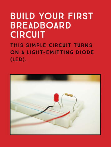
How to build a circuit using a breadboard?To build an electronic or electric circuit, it is highly recommended to follow a circuit schematic ordiagram. The circuit schematic is a pictorial representation of the circuit connections and uses a specialsymbol for each component.We will explain the circuit schematic in a separate tutorial, but we are going to use a simple example tolearn how to build a circuit using the breadboard.Attention! Before we convert the schematic into a real circuit, we must know the main purpose of thecircuit and what results it should give.Remember! When connecting the components to the breadboard we must focus on correct connectionrather the location of the components in the schematic, because a real circuit on a breadboard alwayslooks different than in the schematic.So, let’s start Given the schematic above, the circuit is intended to light the LED whenever the push button is pressed.Steps:1. Place the push button anywhere on the breadboard (do not put both leads on the same row).Connect it from one side to the ground bus (-) a via jumper wire.
2. Connect the other side of the push button directly to the resistor. “Directly” means there’s no needfor jumper wire (remember that the five holes in the same row are connected by default)3. Connect the negative lead (cathode) of the LED directly to the resistor
4. Connect the positive lead (anode) of the LED to the positive bus ( ) via a jumper wire.5. Finally, connect the ground wire (-) from the power supply to the ground bus (-) on the breadboard,then connect the positive wire ( ) from the power supply to the positive bus on the breadboard ( ).6. Press the push button to test the circuit. The LED should light up. ENJOY your first circuit If the circuit doesn’t work, check the connections carefully and follow the steps from the beginning.
Common mistakesSometimes you may wonder why your circuit is not working!Most probably you made a mistake!Connection mistakes on breadboards are not vital, since connections are temporary. You can easilyrearrange the circuit by removing or replacing components.But you must pay attention to some common mistakes and avoid them to save time and finish yourproject smoothly. Here are some mistakes you need to be aware of:Forgetting to connect both sides of the breadboard with jumper wiresAs we mentioned, the left side of the breadboard is totally isolated from the right side, and with somefull-size breadboards the upper half of the power rails is isolated from the lower half. Jumper wires willsolve the problem.Connecting leads to the wrong rowRemember! The five holes in the each row are electrically connected. Do not miss that row.The LED won’t work, because the resistor is connected to the wrong row.
The LED will work, because the resistor is connected to the correct row.Mixing positive ( ) and ground (-) wiresThis is much the same as connecting leads to the wrong row. If you mixed up positive ( ) with ground (-)your circuit is not going to work at all.Wrong connection, because the resistor is connected to the ground bus (-).
Good connection! The resistor must be connected to the positive bus ( ).Reversing polaritySome components have positive ( )and negative (-) leads, such as LEDs and electrolytic capacitors. Youmust consider the correct polarity to avoid damaging the components and the breadboard as well.WRONG! Anode ( ) must always be connected to positive bus ( ), and the Cathode (-) must be connectedto the ground bus (-).
Insufficient contact between leads and clipsIf you leave the leads not pushed firmly inside the breadboard holes, the connection between theconductive clips and components will be weak, this can result in an unstable circuit or not functioningcircuit.Connecting leads of one component in the same rowEach component has at least two leads, and each lead has a different purpose in the circuit. Avoid puttingthe leads of one component in the same row to prevent a circuit short. In the case of ICs, always placethem over the middle divider.The red LED and LM 358 IC are connected the wrong way. While the green LED and 555 IC are connectedproperly.Touching leadsAnother reason for a short the circuit is when components touch each other accidentally. Somecomponents have long leads, such as LEDs and resistors. Try to connect them apart from each other toavoid undesired lead contact.
General tips1. Color-code your circuit. Use red jumper wires for the positive ( ) bus and black wire forground (-). The color does not affect the current flowing through the jumper wire, but with colorcoding you can easily trace circuit connections.2. Use a flexible jumper wire to connect the breadboard with external components to makemovement easier and flexible.Breadboard connected to an external DC motor3. Use solid wires of appropriate length for the internal connections to avoid a “spaghetti” circuit.Spaghetti circuit
Solid wires make the circuit look better.4. If you are using mini breadboards and you find that your circuit requires more roomspace, thereare nubbins and slots on the sides that allow you to connect multiple breadboards together toenlarge the active surface.5. If your project requires you to stick the breadboard permanently (e.g. for a robotic car), you canpeel off the paper layer on the back and use the adhesive surface to attach the breadboard toany surface.Back adhesive layer
Safety instructions1. Do not connect the power supply terminals to each other. This would create a shortcircuit, which may damage the power supply or cause an explosion.2. Do not leave the breadboard connected to a power supply unattended.3. Do not touch the integrated circuit elements with bare hands when the main circuit islive. They are electrostatically sensitive components, and you may easily damagethem with the static charge build up in your body.4. To avoid static electricity, discharge yourself by touching grounded metal or useinsulated chip tweezers to hold the components.5. Do not remove or insert any component in the breadboard while the circuit is live.Disconnect the power from the circuit prior to working on it.6. It is essential to observe correct polarity when connecting certain components (e.g.electrolytic capacitors, piezoelectric speakers, LEDs, power supplies) to the circuit.Reversing the polarity of an electrolytic capacitor will break down the dielectric insidethe capacitor, which will eventually explode.7. If you ever see or smell smoke when building a circuit, you should immediatelydisconnect the power supply.8. Prevent water or any other liquids from getting onto the breadboard. If water spilledonto the breadboard, immediately unplug it from the supply, remove allcomponents, turn it over to allow the water to drain out through the holes, then putit in its original position and leave it to dry at normal room temperature. You can usecompressed air to dry it out, but do not use hot air, because the wet metal strips insidethe breadboard will rust faster when subjected to high temperature.9. Keep your workplace clean and in order.
Quiz1. Choose the correct statement:A. The vertical columns are identified by letters; rows are identified by numbers. The blue line isfor positive ( ,) while the red line is for ground (-).B. The vertical columns are identified by numbers; rows are identified by numbers. The blue line isfor positive ( ), while the red line is for ground (-).C. The vertical columns are identified by letters; rows are identified by numbers. The red line i sfor positive ( ,) while the blue line is for ground (-).2. Which holes are connected to the LED?
3. Which wire closes the circuit in order to light up the red LED?a. Blueb. Yellowc. Greend. Red4. Convert the schematic below into a real circuit using your breadboard, and follow the steps inthe tutorial.
Answers to the quiz1. The correct statement is Number 3.2. From the left side of the breadboard, row no. 10 (five holes from A to E) is to the LEDvia its negative lead (cathode), and the ground bus (-) is connected to the LED via the resistor.From the right side of the breadboard, row no. 10 (five holes from F to J) is connected to the LEDvia its positive lead (Anode), and row no. 15 (five holes) is connected to the LED via the yellowwire. The red wire is not connected to the LED at all.3.The green wire is the correct one to connect the positive lead (anode) to the positive bus( ) on the breadboard.4. Steps to connect two LEDs in parallel with a push button switch: Place the LEDs next to each other (both anodes ( ) connected in one row and cathodes (-)in another row). Take a resistor (of the correct value) and connect the anodes ( ) to the positive bus ( ) via theresistor Connect one side of the push button to the cathodes (-), and connect the other side to theground bus (-) via a jumper wire. Connect the power supply to your breadboard. Hurrah!
In our Electronic Experiments Kit we use the breadboard as the main component on which we carry outthe experiments. Read more about our educational kits on our website and start doing cool projects withthe breadboard.We hope you enjoyed this tutorial. If you liked it, share it with your friends and see other topics on ourwebsite to learn more about electronics through our online tutorials.
The breadboard has a user-friendly construction and quite a safe layout, which make it an important step for newcomers to electronics who wish to test their ideas in quick experiments. However, you can use the breadboard to build all types of electronics projects, starting from very basic circuits to the most complicated robotics.