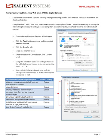
Transcription
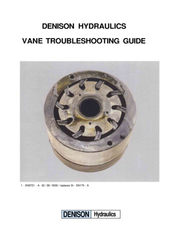
DENISON HYDRAULICSVANE TROUBLESHOOTING GUIDE1 - EN0721 - A 02 / 99 / 5000 / replaces SI - EN175 - ADENISON Hydraulics
VANE TROUBLESHOOTING GUIDE
VANE TROUBLESHOOTING GUIDEV - COMPONENT ANALYSIS CHARTPagesbushing cam 2424343444445MOTORPages1215PUMPside plates vanes46XX47484945XXX46X47XXXX4849
VANE TROUBLESHOOTING GUIDEVANE PUMP COMPONENTS DESIGNATIONPart nb.123456789101112131415part designationEnd capSquare section seal P1 & P2Back-up ring P1 & P2Pressure port plate P2Rotor-insert assembly P2Rear port plate P2BushCam ring P1 & P2O ringRotor-insert assembly P1Square section seal P1 & P2KeyKeyed shaftSplined shaftBall bearingPart nb.1617181920212223242526272829part designationRound section ringMounting capPin-vane holdout (P1 & P2)HousingVane P1 & P2Square section sealScrewDowel pinRear port plate P1Dowel pinPressure port plateScrewShaft sealScrew
VANE TROUBLESHOOTING GUIDECONTENTSIINTRODUCTION2I -1 PRESENTATION2I -2 HOW TO USE THIS GUIDE2I -3 WHY A DENISON VANE PUMP SHOULD NOT BREAK DOWN2I -4 BASIC PRECAUTIONS FOR A LONG LIFE TIME56II ANALYSIS OF FAILURES7II -1 MECHANICAL FAILURESII -2 THE CONSEQUENCES OF MECHANICAL FAILURES12II -3 PRESSURE FAILURES18II -4 PHYSICAL, CHEMICAL OR HYDRAULIC FAILURES24III SPECIFICS OF VANE MOTOR FAILURES AND CAUSES44IV TROUBLESHOOTING TABLE50IV -1 PUMPS51IV -2 MOTORS58V COMPONENT ANALYSIS CHARTFolded first page1
VANE TROUBLESHOOTING GUIDEIINTRODUCTIONI-1 PresentationThe main goal of this guide is to help all theDENIS ON vane pump users to understand theprincipal causes of destruction of these pumpsand motors in service. Our past experience hasshown that the failures, occurring in the first 500hours of service, are premature failures. Failing tofollow instructions or ignoring the correct appli-cation limits and functioning of the units inevitably leads to premature failures. It is important topoint out that 80 % of the failures are linked tofluid contamination incidents (chapter II-4).This guide comes as an addition to the existing"Installation, operation and overhaul instructions" available bulletin S1-EN081.I-2 How to use this guide "The most common causes", chapter II (pages 6 to 43): details of the major incidents you may encounter (cavitation, aeration, misalignment.) and their consequences on the vane pumps. While chapter III(pages 44 to 49) will concern the vane motors. "Fault finding while the pump is running", chapter IV (pages 50 to 60): the troubleshooting tablesfor vane pumps and motors. If you have a problem in working conditions, "the troubleshooting table" willhelp you to find out what is wrong (FAILURE-CAUSE-SOLUTION). "Interpret the physical damages on components", chapter V: The first page (folded) shows a chartwhich summarizes all the pictures of failed components. This will enable you to recognize the failed component and to understand the cause of this failure.I-3 Why a DENISON Vane pump should not break downUnlike most other hydraulic technologies, theDENISON vane pump design is hydraulicallybalanced. You cannot calculate the life time ofthese pumps by calculating the life time of the ballbearing as no internal load (neither axial norradial) is applied on the shaft. The only purpose ofthe ball bearing in the Denison vane pump is to2absorb any external shaft misalignment or abnormal coupling loads.As shown on the drawings hereafter, the two symmetrical high pressure zones have a self centeringeffect on the rotating components.This is a hydrostatic balanced pump, axially andradially.
VANE TROUBLESHOOTING GUIDEDENISON HYDRAULICSVane PumpsSingle series T6 - T7 - B-C-D-E sizesPubl. 034-67110-2 02/98/5000/FBDENISON Hydraulics3
VANE TROUBLESHOOTING GUIDEEach single vane is independently loaded in orderto always be maintained on the cam ring contour.The specific Denison pin design reduces the possible internal leakage, reduces the possiblevane/cam ring wear (due to a precise balancing ofthe forces under and over the vanes), lowers considerably the noise level, allowing higher pressurecapabilities, extends the life time.Added to this licensed pin design, Denison hasengineered the double vane lip technology. Thisvane technology combined with the pin designgives unique overall performances. The double lipsallow the pressure all around the vane to be thesame on the top as on the bottom and as on thesides of it. This is possible because of the doublelips and the balancing through the holes in thevanes. Here again, the components are hydrostatically balanced. Another advantage of the doublelip design is the fact that the first lip seals the lowpressure area and the other one seals the high pressure area. This increases the life time of the pumpwhen working with contaminated oil. The wear,due to the particles of pollution, will have a negative effect, mainly on the first lip. The second lip,working in the high pressure area, keeps its original seal to maintain high volumetric efficiency.This technology is unique because the wear iscompensated. The effect of contamination on theDenison vane design is not a major issue of pumpfailure as for other pump technologies.Every port plate and cam ring has a surface treatment to increase the life time capabilities.4On each cam ring, for example, a dry lubricantcoating is laid on the cam profile. This coatingwill assure, even in bad priming conditions, agood start-up minimizing the risk of micro-seizures. With this dry lubricant coating, the deficiency of oil is compensated but not replaced.This is done for short term deficiencies.Our passed experience shows that the most common failures are linked to the quality of the oil. Assoon as there is a lack of lubricity, the failure isimminent. In addition to the pressure and themechanical failures, all the problems are usually alack of lubrication (rupture of the film of oil). Thefollowings are some examples of the commoncauses:- air in the oil (cavitation, aeration),- solid large size particles,- chemical agents (water, wrong additives, tar.),- too high or too low viscosity,- overheating (shaft alignment),- flow of the system coming back to the pump,- poor quality of oil loosing its main chemicalcharacteristics,This is why good filtration, good thermal stability,good quality of oil, a good design (hose design,bleeder, tank design .), correct hydraulic knowledge (.) will always increase the life time of allhydraulic components.The DENISON vane pump technology is a heavyduty engineering design that will last years if elementary precautions are taken.
VANE TROUBLESHOOTING GUIDEI-4 Basic precautions for a long life time:The Denison vane products are designed for longlife. Some minor precautions can help to avoidpremature breakdowns:- have a correct air bleed at start-up,- always check the oil velocity (inlet & outlet).This should then give the correct sizes of hoses& connectors: maximum velocity of 1,9 m/sec.for the inlet & 6 m/sec. for the outlet,- no strainer on the inlet line is preferred (250microns minimum and check the pressure dropwhen the Viscosity rises),- always pay attention to the viscosity of the oilversus temperature. Even a small change in temperature can have a big effect on the viscosity. Agood quality return line filter is the best solution.- check the pressure at the inlet port, (position ofthe tank, shaft rotational speed.),- ratio flow/tank capacity: is cooling required ?- good shaft alignment is a classic "weakness", aswell as proper coupling with the driving source.The lubrication of these links is also somethingto look after,- proper oil selection versus application condition:viscosity index, viscosity grade (ISO 32,46,68.), environment (biodegradability, fire resistance, normal conditions), pumping temperaturerange, filterability, deaeration, thermal stabilityare the basics to consider for a good fluid,- if the pump is used on a very fast pressurecycling machine, attention should be paid to therelationship between the pressure rise/fall gradient and the inlet pressure in order to avoidcavitation. We recommend maximum limits of5000 bar per second (72500 PSI/ second) forpressure rise and 6000 bar per second (87000PSI) for presssure fall.5
VANE TROUBLESHOOTING GUIDEII ANALYSIS OF FAILURESII -1 MECHANICAL FAILURES7II -2 CONSEQUENCES OF MECHANICAL FAILURES12II -3 PRESSURE FAILURES18II -3-1 Pressure overshoot18II -3-2 Instant pressure overshoot18II -3-3 Consequences of instant pressure overshoot18II -3-4 Cycled overpressurization20II -3-5 Consequences of cycled overpressurization21II -3-6 Pressure gradients23II -3-7 Consequences of too high pressure gradients23II -4 PHYSICAL, CHEMICAL OR HYDRAULIC FAILURES624II-4-1 Start-up without a proper air bleed25II-4-2 Air pollution (Foaming-Aeration, Cavitation-Deaeration)25II-4-2-1 Aeration25II-4-2-2 Consequences of Aeration26II-4-2-3 Cavitation28II-4-2-4 Consequences of Cavitation29II-4-3 Solid particle contamination33II-4-4 Consequences of solid particle contamination33II-4-5 Water contamination37II-4-6 Consequences of Water contamination38II-4-7 Viscosity failures39II-4-8 Consequences of Viscosity failures40II-4-9 Unsuitable fluids41II-4-10 Unsuitable grease43
VANE TROUBLESHOOTING GUIDEIIANALYSIS OF FAILURESThe systematic analysis of failures permits thecauses to be determined logically, these failuresbeing either distortion, shearing, surface seizureor scoring.If the failure is shearing, we can almost certainlysay it is the consequence of a brutal or a fatiguefailure. A brutal failure is due to sudden increasein loads exceeding the material strength limit orits resistance to shocks. A fatigue failure is theresult of the tensile limit of the sensitive point of acomponent.Studying the crystalline faces will allow us todetermine the mechanical causes that provokedthe failure. This troubleshooting guide has beenprepared to allow everyone to quickly reach asatisfactory conclusion. A precise and professionalanalysis to determine the problem is not really thepurpose of this guide.II-1: MECHANICAL FAILURESMechanical failures are due to physical externalparameters that change the mechanical structureof the materials. The causes of these incidents areII-1-1 - Problems onshafts: bad alignment,bad mechanical link(bracket, chassis deformation, bad bell housing, too loose dampingelements.) can create:a) misalignmentmostly axial and radial shaft overloads. Rotarybending (flexion) and torsion (twisted) fatigue failures.consequence page- Fretting P 12, II-2-1- Shaft rupture P 12, II-2-2-1P 13, II-2-2-2- Rear bushing P 15, II-2-5-1P 15, II-2-5-2P 15, II-2-5-3- Cam ring marked P 15, II-2-6- Shaft seal problem P 16, II-2-7- Dissymmetrical wear on portplate P 16, II-2-8- Ball bearing worn or destroyed- Fretting P 12, II-2-1- Shaft rupture P 12, II-2-2-1P 13, II-2-2-2b) out of squareness- Rear bushing P 15, II-2-5-1P 15, II-2-5-2P 15, II-2-5-3- Cam ring marked P 15, II-2-6- Shaft seal problem P 16, II-2-7- Dissymmetrical wear on portplate P 16, II-2-8- Ball bearing worn or destroyed7
VANE TROUBLESHOOTING GUIDEII-1: MECHANICAL FAILURES (continuation)consequence pageII-1-1-1 - Too tight gapbetween the two coupling flanges (axialloads/radial loads).- Fretting corrosion P 12, II-2-1- Shaft rupture P 12, II-2-2-1P 13, II-2-2-2- Ball bearing worn out- Rear bushing P 15, II-2-5-1P 15, II-2-5-2P 15, II-2-5-3- Check with the coupling manufacturer to convenient clearancerequired depending on thetorque.II-1-1-2 - Unbalancedcoupling radial load.- Shaft rupture P 13, II-2-2-2II-1-1-3 - Too high loadon a belt driven system(belt drives not recommended).- Bushing P 15, II-2-5- Cam ring marked P 15, II-2-6- Shaft seal problem P 16, II-2-7- Dissymmetrical wear on portplate P 16, II-2-8II-1-1-4 - Non-homoki-netic transmission dueto unbalanced cardanshaft (or universal joint)means inconstant shaftspeed.- Shaft rupture P 13, II-2-2-2II-1-1-5 - Too greatmoment of inertia dueto heavy couplings (likechain couplings) orvery large diametercouplings.8- Bushing P 15, II-2-5- Cam ring marked P 15, II-2-6- Shaft seal problem P 16, II-2-7
VANE TROUBLESHOOTING GUIDEII-1: MECHANICAL FAILURES (continuation)consequence pageII-1-1-6 - Bracket chassis deformation (whenpump under load).- Shaft rapture P 12, II-2-2-1P 13, II-2-2-2- Bushing problems P 15, II-2-5- Marked cam ring P 15, II-2-6- Seal problems P 16, II-2-7- Wear on port plate P 16, II-2-8II-1-1-7 - Hose strain(reaction) force (brutalpressure compression /decompression, rigid- Shaft rapture P 12, II-2-2-1P 13, II-2-2-2- Bushing problems P 15, II-2-5hoses mounting- Marked cam ring P 15, II-2-6strain.).- Seal problems P 16, II-2-7- Wear on port plate P 16, II-2-8II-1-1-8 - Over torquelimits (too high pressure versus displacementfor the capacity of theshaft chosen).- Shaft rapture P 13, II-2-2-3(torsional fatigue)- Shaft wear P 14, II-2-3P 14, II-2-4II-1-2 - Badshaft/couplingconnection:II-1-2-1 - "Couplingscrew" not properlypositioned on the key(keyed shaft).- Shaft rapture P 12, II-2-2-1P 13, II-2-2-2- Rear bushing P 15, II-2-5-1P 15, II-2-5-2P 15, II-2-5-39
VANE TROUBLESHOOTING GUIDEII-1: MECHANICAL FAILURES (continuation)consequence pageII-1-2-2 - Bad manufacturing (machining)of the couplings:- bad diameter fit tolerance between the shaftdiameter and the coupling diameter- Fretting P 12, II-2-1- Shaft rupture P 13, II-2-2-3- Shaft worn out P 14, II-2-4- key way in the coupling is not properlycentered with the mainbore axis- Shaft rupture P 14, II-2-3P 14, II-2-4- bad heat treatment(too high or too low)II-1-2-3 - Shaft not pro- Wear of the splines P 14, II-2-3perly utilized (too smallsurface of spline or keyused)- Wear of the key P 14, II-2-4II-1-2-4 - Bad (or no)lubrication of splinedshafts/coupling.II-1-3 - Cartridgedowel pin not positioned correctly inthe housing.10- S
DENISON vane pump design is hydraulically balanced. You cannot calculate the life time of these pumps by calculating the life time of th e ball bearing as no internal load (neither axial nor radial) is applied on the shaft. The only purpose of the ball bearing in the Denison vane pump is to absorb any external shaft misalignment or abnor-