Transcription
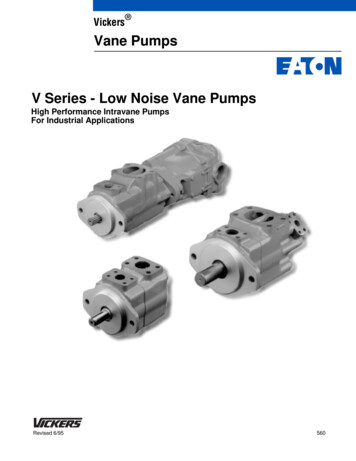
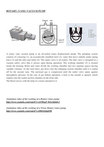
ROTARY (VANE) VACUUM PUMPA rotary vane vacuum pump is an oil-sealed rotary displacement pump. The pumping systemconsists of a housing (1), an eccentrically installed rotor (2), vanes that move radially under springforce (3) and the inlet and outlet (4). The outlet valve is oil-sealed. The inlet valve is designed as avacuum safety valve that is always open during operation. The working chamber (5) is locatedinside the housing. Rotor and vanes divide the working chamber into two separate spaces havingvariable volumes. As the rotor turns, gas flows into the enlarging suction chamber until it is sealedoff by the second vane. The enclosed gas is compressed until the outlet valve opens againstatmospheric pressure. In the case of gas ballast operation, a hole to the outside is opened, whichempties into the sealed suction chamber on the front side.The Rotor moves with the help of a motor attached to it.Animation video of the working of a Rotary (vane) pumphttp://www.youtube.com/watch?v AFHogF-9eGA&hd 1Animation video of the working of a Trivac Rotary (vane) pumphttp://www.youtube.com/watch?v IIKOx0JqE08
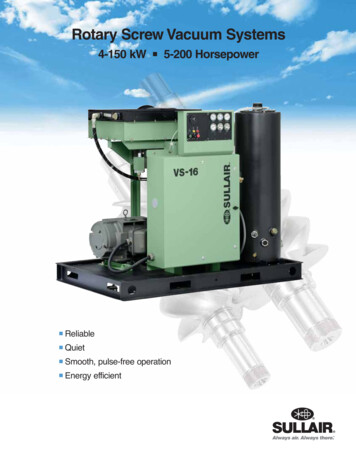
DIAPHRAGM VACUUM PUMPDiaphragm vacuum pumps are dry positive-displacement pumps. A crankshaft-driven connectingrod (4) moves the diaphragm (1) that is tensioned between head cover (2) and housing (3). Thespace between the head cover and the diaphragm forms the suction chamber (5). Diaphragm pumpsrequire inlet valves and outlet valves (6) to achieve gas displacement. Pressure-controlled shuttervalves made of elastomer materials are used as valves.First the diaphragm is pulled down, creating low pressure in the suction chamber. The inlet valve(left valve) opens and gas is sucked into the chamber. Because of high pressure on the exhaust side(right valve), it remains closed.Because the suction chamber is hermetically sealed off from the drive by the diaphragm, the pumpmedium can neither be contaminated by oil nor can aggressive media corrode the mechanics. Theharmful space between the outlet valve and the suction chamber results in only a limitedcompression ratio. This means that an ultimate pressure of only approximately 70 mbar can beattained with a single pump stage. Connecting multiple pumping stages in series can reduce ultimatepressure to 0.5 mbar. Lower pressures cannot be achieved, as in this case there is no longersufficient force to open the inlet valve.
SCROLL VACUUM PUMPScroll pumps are an excellent alternative to rotary vane pumps where oil free pumping is desirable.-2The ultimate vacuum achieved by a Scroll pump is 1x10 mbar.A scroll pump (also called as a spiral compressor, a scroll pump or a scroll vacuum pump) is adevice for compressing fluids such as liquids and gases.A scroll pump uses two interleaved Archimedean spiral scrolls to pump, compress orpressurize fluids. One of the scrolls is fixed, while the other orbits eccentrically without rotating,thereby trapping pockets of gas molecules between the scrolls.Video of the working of Edwards Scroll Vacuum Pumphttp://www.youtube.com/watch?v s3xulCRrjos
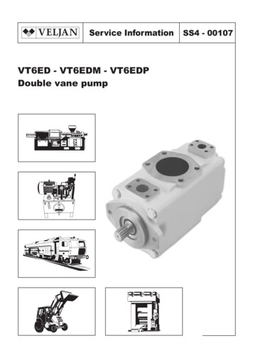
OIL DIFFUSION VACUUM PUMPThe oil diffusion pump is operated with an oil of lowvapor pressure.A high speed jet of the Oil is generated by boiling theOil and directing the vapor through a jet assembly.Note that the oil is gaseous when entering the nozzles.Within the nozzles, the flow changes from laminar,to supersonic and molecular. Often several jets areused in series to enhance the pumping action. Theoutside of the diffusion pump is cooled using either airflow or a water line. As the vapor jet hits the outercooled shell of the diffusion pump, the working fluidcondenses and is recovered and directed back to theboiler. The pumped gases continue flowing to the baseof the pump at increased pressure, flowing out throughthe diffusion pump outlet, where they are compressed to ambient pressure by the secondarymechanical forepump and exhausted.Diffusion pumps cannot discharge directly into the atmosphere, so a mechanical forepump istypically used to maintain an outlet pressure around 0.1 mbar.Diffusion pumps have no moving parts and as a result are quite durable and reliable. They canfunction over pressure ranges of 10 10 to 10 2 mbar. They are driven only by convection and thushave a very low energy efficiency and low cost per unit pumping speed when compared with othertypes of pump used in the same vacuum range.One major disadvantage of diffusion pumps is the tendency to backstream oil into the chamberbeing evacuated. This oil can contaminate surfaces inside the chamber or upon contact with hotfilaments or electrical discharges may result in carbonaceous or siliceous deposits.Generally cold traps and baffles are utilized between the chamber and the diffusion pump tominimize backstreaming, although this results in some loss of pumping ability.The oil of a diffusion pump cannot be exposed to the atmosphere when hot. If this occurs, the oilwill burn and has to be replaced.Animation video of the working of a Diffusion ource/Corporate/About Us/diffusion pump.swf
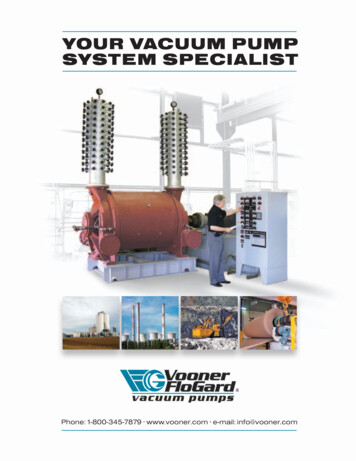
TURBO-MOLECULAR VACUUM PUMP (TMP)A turbo-molecular pump (TMP) or turbopump reduces the pressure of the chamber to which it isconnected from about 10-2 Torr to about 10-8 Torr. A TMP consists of a stack of rotors withblades, or slots, depending on the specific pump. In between rotor disks are stators, fixed discs thatcontain the same blades, or slots, as the rotors, but oriented in the opposite direction.The motor makes the rotor spin about the axis. The stators are fixed disks in between rotors, andthe vent is a hole through which we can let a gas through if we wish to bring the pump back to ahigher pressure. The big arrows show the flow of pumped molecules from the attached chamber.When the blades, spinning at 20000 rpm (about 2100 rad/s), hit the molecules, they impartmomentum on these. Because of the angle of orientation of the blades of the rotor and the stator,the molecules move down to the next rotor. This succession of rotor-stator pairs drives themolecules towards the exhaust, where they are collected by a backing pump.When the chamber is at atmospheric pressure, the flow of gases is described as "viscousflow", where the molecules move in bulk and interact with each other much more significantlythan they do with the walls of the container. Most turbopumps cannot work in this regime. Thereason is the force exerted by a blade on a molecule is not significant compared with the collisionsbetween the molecules, and so the general flow remains unaffected. For this reason, a rotary pumphas to remove the gas molecules before the turbopump is turned on, down to about 10-2 Torr. Atthis pressure, the flow is called "molecular flow", meaning that molecules are relatively free and,to a good approximation, do not interact with each other. In this regime, the turbopump impartsmomentum on the gas molecules independently, so they can properly go move downwardstowards the other end of the pump. Once turned on, the turbopump will work for quite a long timereducing the chamber pressure, until at some point the pressure will not go down significantly anylonger. This happens between 10-6 and 10-8 Torr.Video of the working of Oerlikon-Leybold Turbo-Molecular Pumphttp://www.youtube.com/watch?v XOca57gPsq4Video of the working of Agilent Vacuum TechnologyTurbo-Molecular Pumphttp://www.youtube.com/watch?v xIfOHrXyoJoParts of Agilent Technology TMPhttp://www.youtube.com/watch?v 1xZe1H2XHhM&list PL6755BEABF7E7D01D&hd 1
ION GETTER VACUUM PUMP (IGP)The ion pump operates between pressures ranging from 10-4 mbar to 10-10 mbar.An Ion getter pump consists of an array of positively charged, parallel axis, cylindrical anodes. Tothe left and right of this array are two chemically reactive titanium plates (whose normal vectorspoint along the axes of the anodes) which are kept at a negative electric potential. Still outside ofthese plates lie permanent magnets which establish a magnetic field whose lines lie along the axesof the anodes. A penning cell or trap is thus formed between each anode cylinder with the cathodetitanium plates at each end and the permanent magnets outside the plates.Once the ion pump has been evacuated to an appropriate starting pressure of 10-4 mbar, a positivehigh voltage is applied to the anodes. The electric discharge between the anode and the cathodeproduces an electron cloud within the penning cells. Because of the magnetic field induced bypermanent magnets, the electrons are forced on spiral orbits.Incoming neutral gas atoms and molecules are ionized after colliding with the electron plasmahaving sufficient energy. The electrons freed during the process become a part of the electron cloudand help ionizing other molecules themselves. The initial gas molecule is left as a positive ionwithin the positively charged high voltage anode. Under the action of strong electromagnetic forcesthe positive ions are accelerated towards the negatively charged Titanium cathode plates collidingwith it at a high kinetic energy.Upon collision, the positive gas ions react with the cathode, combining chemically with a cathodeatom. In this case, neutral atoms are set free from the cathode. This "sputtering" action distributescathode material throughout the ion pump, enabling fresh cathode material to be available forchemical combination (getter) with reactive gases. If the ionized gas molecules do not readily reactwith the cathode material, it is implanted into the cathode material or reflected under a definedangle. The ionized gas molecule becomes neutrally charged at the moment of impact.Hence the removal of gas molecules (evacuation) from the pressure system is either chemical orphysical and depends upon the gas species as well as the cathode material.Ion getter pumps require a pressure of 10-4 mbar and less for operation. At this pressure theelectron cloud and gas ionization occurs within each penning cell. At higher pressures, ionizationoccurs outside the anode area and hence proper electric field is not maintained. At these pressures,voltage applied to the anodes can damage the pump.Ion pumps have no moving parts and use no oil. They are therefore clean, need little maintenance,and produce no vibrations. These advantages make ion pumps well-suited for use in scanning probemicroscopy and other high-precision apparatus.
Diaphragm vacuum pumps are dry positivedisplacement pumps. A crankshaft- -driven connecting rod (4) moves the diaphragm (1) that is tensioned between head cover (2) and housing (3). The space between the head cover and the diaphragm forms the suction chamber (5). Diaphragm pumps requ