Transcription
DENISON HYDRAULICSgoldcup seriesclosed circuit piston pumpsP6, P7, P8Sservice informationPubl. LT3-00058-2 Replaces S1-AM025-ARevised 9/02E-Mail: denison@denisonhydraulics.comInternet: http://www.denisonhydraulics.comwww.comoso.com
CONTENTSPAGEinstallationtypical characteristicsfluid connectionsgeneraldescriptionmountingshaft informationpipingservice informationrecommended fluidsviscosityviscosity indextemperaturealternate fluidsmaintenancefluid cleanliness for new installationstart-up procedurecomparison of solid contamination classification systemtroubleshootingassembly tool drawings, T1, T2, T3, T4, T5disassemblyrework of wear partsassemblydrive shaft and bearingbarrel and auxiliary drive shaftrocker campistons and shoesmounting flange, cam & cradlehousinghousing, end cap, cam and barrelport blockmounting port block to housinggerotor and barrel holddownvalve block (before 7-93)valve block (after 7-93)valve block for special mounting of servo valve (before 7-93)valve block for special mounting of servo valve (after 7-93)output controlsinput controlsshaft and seal installationmechanical shaft seal assembly procedurecounter-balance servo stemrear drive adapterpilot valveshuttle valveshuttle valve mountingimportant instructionsinstructions for replenishing circuit isolation plughydraulic circuittest proceduregeneral requirementsbasic pump test(refer to manual S1-AM030 for controls service information)ordering codeseal kitscompletevalve blockHI-IQ valve blockshaft seal replacementshaft sealshuttle valveNote: New revisions are shown underlined.Pages are marked Revised where changes have been 6S23-15089
INSTALLATIONTYPICAL CHARACTERISTICSSpecificationTermP6P7P8 displacement at max. anglein.3/rev.cm3/rev6.00(98)7.25(119)8.00(131) pressure ports A & B max.continuousmax. )6000(414)3600(248)4350(300) speed, max. continuousrpm300030001800 flow, ports A or B @ 1500 RPM gpm(theoretical )L/min.38.9(147)47.1(178)51.9(196) flow, ports A or B @ 1800 RPM gpm(theoretical )L/min.46.8(177)56.9(214)62.3(236) flow, internal replenishing pump gpm@ 1800 RPM (theoretical )L/min.6.9(26.1)6.9(26.1)6.9(26.1) flow, auxiliary pump, externalat 1800 RPM (theoretical)(see note)gpmL/min.9.3(35.2)9.3(35.2)9.3(35.2) replenishing pressurepsibar200(14)200(14)200(14) servo 23-37) mounting-2 bolt flangeSAECCC shaft-splinekeyedSAECCC fluid connection ports A & BSAE-4 bolt pad for 6000split flangeinmm1-1/2(38.1)1-1/2(38.1)1-1/2(38.1) weight w/rotary servolbs.kg.335(152)335(152)335(152)Note: Any SAE-A or B mount pump may be used with the appropriate external driveThe product information, specifications, and descriptions contained in this publication have beencompiled for the use and convenience of our customers from information furnished by the manufacturer; and we can not, and do not, accept any responsibility for the accuracy or correctnessof any description, calculation, specification, or information contained herein. No such description, calculation, specification, or information regarding the products being sold has been madepart of the basis of the bargain, nor has same created or amounted to an express warranty thatthe products would conform thereto. We are selling the goods and merchandise illustratedand described on this publication on an "as is" basis, and disclaim any implied warranty,including any warranty of merchantability or warranty of fitness for any particular purposewhatsoever, with respect to the goods and merchandise sold. All manufacturer warrantiesshall be passed on to our customers, but we shall not be responsible for special, indirect, incidental, or consequential damages resulting from the use of any of the products or informationcontained or described on this publication. Further, we reserve the right to revise or otherwisemake product improvements at any time without notification.3www.comoso.com
INSTALLATIONportAAG, BGBCD1, D2D3DGDSFA, FBGHIKKAKGMSVA/VBsize1 1/2" 4 bolt SAE 6000 psiSAE - 6 straight thread1 1/2" 4 bolt SAE 6000 psiSAE - 16 straight threadSAE - 12 straight threadSAE - 16 straight threadSAE - 6 straight threadSAE - 4 straight thread1/4 - 18 dryseal NPTFSAE - 8 straight threadSAE - 8 straight threadSAE -16 straight threadSAE - 1 1/4 3000 psi, 4-bolt padSAE -16 straight threadSAE - 12 straight threadSAE - 6 straight threadSAE - 8 straight threadSAE - 8 straight threadSAE - 4 straight threadConversion Adapter Kit “A” mount S23-12438-0“B” mount letsystem pressure gage, ea. sideoutlet/inletinternal auxiliary pump inletcase drainreplenishing relief draincase pressure gageshuttle repl. pilot drain (ext.drain)control pressure gage, ea. sideint. aux. pump outlet to filterfilter returninlet to optional pump (gear pump)optional - vane pumpaux. replenishing portaux. repl. inlet to shuttlereplenishing pressure gageauxiliary servovalve drainservovalve inletindividual compensator vent
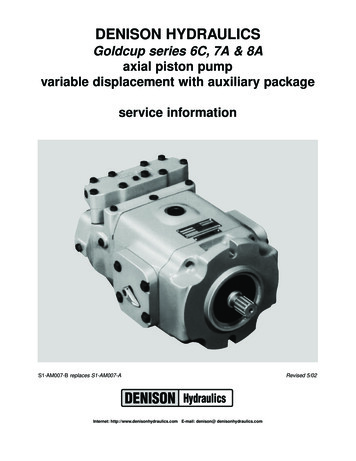
INSTALLATIONGENERALThe DENISON HYDRAULICS Goldcup 6, 7, and 8 axial piston pumps feature advancedesign concepts which are time proven and provide for advance pumping and controlconcepts. The instructions contained in this manual cover complete disassembly andreassembly of the unit. Before proceeding with the disassembly or reassembly of anyunit, this manual should be studied in order to become familiar with proper order andparts nomenclature.DESCRIPTIONThe use of a rocker cam to control the pump displacement provides a small packagesize, reduces wear, and speeds control response. The control vane actuator eliminateslinkage and backlash inherent in typical stroking cylinder designs.Standard controls for the Goldcup units are Rotary Servo and Compensator Override.Additional optional controls are also available.MOUNTINGThis pump is designed to operate in any position. The mounting hub and four bolt mounting flange are in full conformance with SAE standard. The pump shaft must be in alignment with the shaft of the driven load and should be checked with a dial indicator. Themounting pad or adaptor into which the fluid pump pilots must be concentric with the pumpshaft to prevent bearing failure. This concentricity is particularly important if the shaft isrigidly connected to the driven load without a flexible coupling.SHAFT INFORMATIONSplined: The shafts will accept a maximum misalignment of 0.006" TIR (.15 mm).Angular misalignment at the male and female spline axes must be less than .002” perinch radius (.002 mm per mm radius). The coupling interface must be lubricated. DENISON HYDRAULICS recommends lithium molybdenum disulfide or similar grease. Thefemale coupling should be hardened to 27-45 Rc and must conform to SAE-J498B(1971) Class 1 flat root side fit.Keyed: High strength heat treated keys must be used. Replacement keys must be hardened to 27-34 Rc. The key corners must be chamfered .030"-.040" (.75-1 mm) at 45 toclear radii that exist in the keyway.Splined or Keyed: Both types of shafts will accept a side load of 170 lbs. (77 kg) at thecenter of the spline or key, with a B10 life of 10,000 hours at 1800 RPM.PIPINGConnect inlet and outlet lines to the port block of the pump.The maximum case pressure is 75 PSI (5.17 bar) continuous, 125 PSI (8.6 bar) intermittent. Case pressures must never exceed inlet pressure by more than 25 PSI (1.7 bar).When connecting case drain line make certain that drain plumbing passes above highest point of the pump before passing to the reservoir. If not, install a 5 PSI (.3 bar) casepressure check valve to be certain the case is filled with oil at all times.The case leakage line must be of sufficient size to prevent back pressure in excess of 75PSI (5.7 bar) and returned to the reservoir below the surface of the oil as far from thesupply suction as possible. All fluid lines, whether pipe, tubing, or hose must be adequatesize and strength to assure free flow through the pump. An undersized inlet line will prevent the pump from reaching full speed and torque. An undersized outlet line will createback pressure and cause improper operation. Flexible hose lines are recommended. Ifrigid piping is used, the workmanship must be accurate to eliminate strain on the pumpport block or to the fluid connections. Sharp bends in the lines must be eliminated wherever possible. All system piping must be cleaned with solvent or equivalent beforeinstalling pump. Make sure the entire hydraulic system is free of dirt, lint, scale, or otherforeign material.Caution: Do not use galvanized pipe. Galvanized coating can flake off withcontinued use.SERVICE INFORMATIONThese hydraulic products are designed to give long dependable service when properlyapplied and their systems properly maintained. These general instructions apply to typical systems. Specific instructions for particular equipment can be developed from them.RECOMMENDED FLUIDSSee DENISON HYDRAULICS bulletin SPO-AM305 for more details.5Revisedwww.comoso.com
INSTALLATIONFILLING CASEIt is essential to make certain that the case (pump housing) is as full of fluid as possibleand remains full during operation and at rest.Always fill to the highest available point. Remove a plug or screw and allow the oil toescape through this point.Recommended fill points:Mounting orientation vertical, shaft up.D1 or D2 (drain) port in housingVent DG2 port in mounting flange (new units)or one of the upper screws which attach thecontrol. See installation drawing.Vertical, shaft down 1) or horizontaldrain ports to the sideD1 or D2 (drain port in housing.1) Vent DG (case gage) port in port block.MAINTENANCEThis pump is self-lubricating and preventative maintenance is limited to keeping systemfluid clean by changing filters frequently. Keep all fittings and screws tight. Do not operate at pressures and speeds in excess of the recommended limit. If the pump does notoperate properly, check the Trouble Shooting Chart before attempting to overhaul theunit. Overhauling is relatively simple and may be accomplished by referring to theDisassembly, Rework Limits of Wear Parts and Assembly Procedures.FLUID CLEANLINESSFluid must be cleaned before and continuously during operation by filters that maintain acleanliness level of NAS 1638 Class 8.START UP PROCEDURE Read and understand the instruction manual. Identify components and their function. Visually inspect components and lines for possible damage. Check reservoir for cleanliness and drain and clean as required. Check fluid level and fill as required with filtered fluid at least as clean as that recommended. Fill pump case with clean oil prior to starting. Check alignment of drive. Check oil cooler and activate it, if included in circuit. Check fluid temperature. Reduce pressure settings of relief valve. Make sure accurate pressure readings can bemade at appropriate places. If solenoids in system, check for actuation. Start pump drive. Make sure pump and motor fill properly. Bleed system of air. Recheck fluid level. Cycle unloaded machine at low pressure and observe actuation (at low speed, ifpossible). Increase pressure settings gradually in steps. Check for leaks in all lines especially inpump and motor inlet lines. Make correct pressure adjustments. Gradually increase speed. Be alert for trouble as indicated by changes in sounds, system shocks and air in fluid. Equipment is operational.6Revisedwww.comoso.com
TROUBLESHOOTINGTROUBLESHOOTINGComponent problems and circuit problems are often inter-related. An improper circuitmay operate with apparent success but will cause failure of a particular component within it. The component failure is the effect, not the cause of the problem.This general guide is offered to help in locating and eliminating the cause of problems bystudying their effects:effect of troublenoisy pumperosion on barrelports and portplatehigh wear inpump and motor7possible cause fault which needs remedyair in fluidleak in suction lineleak at shaft seallow fluid levelturbulent fluidreturn lines above fluid levelgas leak from accumulatorexcessive pressure drop in the inlet line from apressurized reservoirsuction line strainer acting as air trapcavitation influid too coldpump or motor fluid too viscousrotating group fluid too heavyshaft speed too highsuction line too smallsuction line collapsedsuction strainer too smallsuction strainer too dirtyoperating altitude too highboost or replenishment pressure too lowreplenishment flow too small for dynamic conditionsmisaligned shaft faulty installationdistortion in mountingaxial interferencefaulty couplingexcessive overhung loadsmechanical fault piston and shoe looseness or failurein pumpbearing failureincorrect port plate selection or indexeroded or worn parts in the displacement controlair in fluidsee abovecavitationsee aboveexcessive loadsreduce pressure settingsreduce speedscontaminantimproper filter maintenanceparticles in fluid filters too coarseintroduction of dirty fluid to systemreservoir openingsimproper reservoir breatherimproper line replacementwww.comoso.com
TROUBLESHOOTINGTROUBLESHOOTING(continued)8effect of trouble possible cause fault which needs remedyhigh wear inImproper fluidfluid too thin or thick for operating temperature rangepump and motorbreakdown of fluid with ct additives in new fluiddestruction of additive effectiveness with chemicalagingimproper repair incorrect partsincorrect procedures, dimensions, finishesunwanted water condensationin fluidfaulty breather/strainerheat exchanger leakagefaulty clean-up practicewater in makeup fluidpressure shocks cogging loadmechanical considerationsworn relief valve needed repairswornneeded repairscompensatorslow response in replace or relocatecheck valvesservo pr
basic pump test 41 (refer to manual S1-AM030 for controls service information) ordering code 43 seal kits complete S23-15092 valve block S23-00135 HI-IQ valve block S13-04226 shaft seal replacement S23-44302 shaft seal 623-00006 shuttle valve S23-15089 Note: New revisions are shown underlined. Pages are marked Revisedwhere changes have been .