Transcription
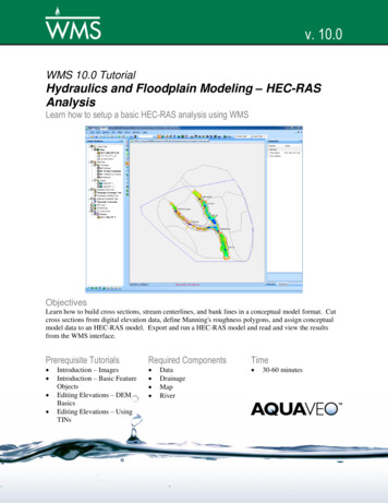
v. 10.0WMS 10.0 TutorialHydraulics and Floodplain Modeling – HEC-RASAnalysisLearn how to setup a basic HEC-RAS analysis using WMSObjectivesLearn how to build cross sections, stream centerlines, and bank lines in a conceptual model format. Cutcross sections from digital elevation data, define Manning's roughness polygons, and assign conceptualmodel data to an HEC-RAS model. Export and run a HEC-RAS model and read and view the resultsfrom the WMS interface.Prerequisite Tutorials Introduction – ImagesIntroduction – Basic FeatureObjectsEditing Elevations – DEMBasicsEditing Elevations – UsingTINsRequired Components DataDrainageMapRiverPage 1 of 17Time 30-60 minutes Aquaveo 2015
1Contents123456782Contents . 2Introduction . 2Objectives . 2Preparing the Conceptual Model . 24.1Getting a Background Image . 34.2Create a local copy of the images . 44.3Open Background Image . 54.4TIN Display Options . 54.5Creating the Coverages . 54.6Creating the Centerline and Bank Arcs . 54.7Naming the Centerline Arcs . 74.8Creating Land Use / Materials Coverage . 84.9Creating the Cross Sections . 94.10Extracting Cross Sections . 10Creating the Network Schematic . 11Creating the HEC-RAS Project File . 13Using HEC-RAS . 14Post-Processing . 16IntroductionHEC-RAS was developed by the U.S. Army Corps of Engineers Hydrologic EngineeringCenter. HEC-RAS performs a step backwater curve analysis for either steady state ortransient conditions to determine water surface elevations and velocities.3ObjectivesIn this exercise, you will learn how to use the WMS River tools to construct a HEC-RASsteady flow model. This includes the following:4 Building the conceptual model Mapping the conceptual data to a hydraulic model representation Running the simulation within HEC-RAS Viewing results in WMSPreparing the Conceptual ModelThe first step to creating an HEC-RAS model is to create a conceptual model whichdefines the river reaches (layout and attributes), the position of cross sections on thosereaches (orientation and station values), bank locations, and material zones. Theconceptual model will be used to create a network schematic inside the River module.We will create the conceptual model from a USGS quad map as well as scatteredbathymetric (elevation) data in the form of a TIN.Page 2 of 17 Aquaveo 2015
Hydraulics and Floodplain Modeling – HEC-RAS AnalysisWMS Tutorials1. Close all instances of WMS2. Open WMS3. Select Display Display Projection to set your current projection system.4. Select Global Projection, then the Set Projection button5. Set Projection to State Plane Coordinate System, Datum to NAD 83,Planar Units to FEET (U.S. SURVEY), and Zone to North Carolina (FIPS3200).6. Select OK7. Set Vertical Units to U.S. Survey Feet8. Select OK9. Select File Open10. Locate the hecras folder in the files for this tutorial. If needed, downloadthe tutorial files from www.aquaveo.com.11. Open “wmsras.tin”Skip sections 4.1 and 4.2 if you are not able to connect to the Internet using yourcomputer.4.1Getting a Background ImageUsing an Internet connection you can load a background image (Aerial photo or a topomap) for the project site. You can use any of the Get Data tools in WMS to load imagesfrom the internet.1. Select the Get Online Maps tooldown menuwill appear.located in the Add GIS Data drop-in the Get Data menu bar. The Get Online Maps dialog2. Select World Imagery and World Top Map and click OK.Page 3 of 17 Aquaveo 2015
WMS TutorialsHydraulics and Floodplain Modeling – HEC-RAS Analysis3. WMS will load the background image files. It will take a few momentsdepending upon your internet connection. Once done, you can see an aerialphoto and a topo map added to the background.4.2Create a local copy of the imagesThe images you just loaded are read in from a server and sometimes take a long time tozoom and pan around. You can create a local copy of the image to expedite suchnavigations.1. In the project explorer, under the GIS Data folder, right click one of theimages and select Export.2. Select OK to accept the suggested value of the resample ratio. A resamplemagnification factor of 1 means that the image will have exactly as manypixels as it is being displayed on the screen. You can increase the factor ifyou need a higher resolution image. But, note that it will take a longer timeto download.3. Assign a name to the image you are about to download and the locationwhere it will be saved. WMS will download and save the image in thespecified location in your local drive. You can see the download progress.4. Once the image has been downloaded, you can remove the bigger onlineimages (the ones that have a little globe on their icon). To do this, rightclick on the online image under the GIS Data folder and select Delete.5. Repeat the same process for the other image and this time set the resamplemagnification factor to 1.If you were able to successfully complete all the steps in sections 4.1 and 4.2 you can skipsection 4.3.Page 4 of 17 Aquaveo 2015
Hydraulics and Floodplain Modeling – HEC-RAS AnalysisWMS Tutorials4.3Open Background ImageIf you do not have reliable internet access, you should open an image showing the areawe are interested in modeling as follows:1. Select File Open2. Open “wmsras.jpg”4.4TIN Display OptionsThe TIN clutters the screen, yet we want to know where it is so we do not create ourconceptual model outside the domain of our bathymetric data. To better see the image,we will turn off the display of TIN triangles, vertices, and contours, and turn on the TINboundary. To do this:1. Right-click on the New TIN under Terrain Data in the Project Explorer andselect Display Options2. On the TIN tab, uncheck the Unlocked vertices toggle box (it may alreadybe unchecked)3. Uncheck the Triangles and the TIN Contours toggle boxes4. Ensure that the Boundaries box is checked5. Select OK4.5Creating the CoveragesWe need to create a centerline coverage for our reaches and a cross section coverage forour cross sections. These will form the core of our conceptual model.1. Right-click on the Coverages folder within the Project Explorer and chooseNew Coverage2. Change the coverage type to 1D-Hyd Centerline3. Select OK4. Create another new coverage and set its coverage type to 1D-Hyd CrossSection5. Select OK6. Activate the centerline coverage by single-clicking on its name in theProject Explorer4.6Creating the Centerline and Bank ArcsCenterline arcs are used to define the locations and lengths of the study reaches andassign their attributes. We will have a centerline following the main channel as well asthe tributary on the west. As the flows below the reservoir in the tributary on the East ofthe Leith Creek are small, we will disregard that reach in our simulation. To create thecenterline arcs:1. Before creating the feature arcs and to clearly see the referencebackground images, right click on the World Topo Map image you justPage 5 of 17 Aquaveo 2015
WMS TutorialsHydraulics and Floodplain Modeling – HEC-RAS Analysisconverted and select Set Transparency and set the imagetransparency to 40%.2. In the Map Module Select the Create Feature Arc tool3. Following the pattern in Figure 4-1, create the centerline of the mainchannel from upstream to downstream (HEC-RAS views a river inthe upstream to downstream direction and it will ultimately help definethe left bank and right bank characteristics) by clicking points on thecenterline one at a time. Double-click the last point to indicate that it isthe end of the centerline.Main ChannelWest TributaryFigure 4-1: Creating the Centerline arcs4. Create the arc for the west tributary, upstream to downstream, byclicking points on the centerline. Create the last point where thetributary meets the main channel by clicking on the main channelcenterline. This splits the centerline of the main channel into tworeaches.This defines the centerline for the model in this simulation. It will consist of two reachesin the main channel (divided by the tributary), and one reach in the west tributary.Bank arcs are used to define the locations of the banks and the over-bank distances. Thenext step is to create bank arcs along both sides of each centerline arc. To create the bankarcs:5. Select the Create Feature Arc tool6. Create new arcs where you estimate the bank locations to be, basedupon contours/colors (roughly follow the green area around thecenterline arcs) on the background image. Use Figure 4-2 as a guide.Page 6 of 17 Aquaveo 2015
Hydraulics and Floodplain Modeling – HEC-RAS AnalysisWMS TutorialsBanksFigure 4-2: Placement of Bank arcs1. Choose the Select Feature Arc tool2. Select all of the bank arcs (hold the SHIFT key down while selecting inorder to multi-select arcs)3. Select Feature Objects Attributes4. Change the Arc Type to Bank5. Select OK6. The background images are no longer necessary; uncheck the toggle boxnext to the images folder.4.7Naming the Centerline ArcsReaches are stream sections where the flow rates and other hydraulic conditions areassumed to be constant. A river can be comprised of one or more reaches, but only oneflow path. HEC-RAS has the ability to model multiple rivers (flow paths). To assignnames to our rivers and reaches:1. Double-click the uppermost reach in the main channel2. Make sure the Arc type is set to Centerline3. Select OK4. Enter Leith Creek for the River Name5. Enter Upper Main for the Reach Name6. Select OK7. Repeat steps 1 to 4 for each reach in the map as shown in Figure 4-3.NOTE: For the Lower Main reach you can choose Leith Creek from the river namecombo box instead of typing it in.Page 7 of 17 Aquaveo 2015
WMS TutorialsHydraulics and Floodplain Modeling – HEC-RAS AnalysisFigure 4-3: River and Reach Names4.8Creating Land Use / Materials CoverageOne of the properties HEC-RAS uses is roughness values. We will designate materials todifferent areas of our model. Later we will assign each material a roughness value. Thematerial zones are stored in WMS as an Area Property coverage. To load the materialsdata:1. Select File Open2. Open the file “Materials.map”3. Select Edit Materials4. Click the New button 5 times in order to create 5 new material types5. Rename the materials as shown below in Figure 4-4Figure 4-4: materials for use in the Area Property coveragePage 8 of 17 Aquaveo 2015
Hydraulics and Floodplain Modeling – HEC-RAS AnalysisWMS Tutorials6. If you wish, you may set the color and pattern to better match thedescriptions.7. Select OK to close the Materials Data dialog8. Make sure the newly created area property coverage, Materials, is active inthe Project Explorer9. Right-click on the Materials coverage and choose Properties10. Change the Coverage type to Area Property and enter “Materials” as thecoverage name11. Select OKNow that you have defined all the materials, you will assign a material type to eachpolygon in the Materials coverage.12. Select the Select Feature Polygon tool13. Double-click on the polygon that defines the river area (see Figure 4-5)14. Set the polygon type to Material and choose river from the drop-down list15. Select OK16. Using Figure 4-5 as a guide, define material types for the remainingpolygons (remember you can also double-click on a polygon to bring upthe attributes dialog)Figure 4-5: Materials used in HEC-RAS Simulation4.9Creating the Cross SectionsHEC-RAS associates most of its model data with cross sections and generates solutionsor output at the cross sections. Therefore, cross sections are the most important part of themap. HEC-RAS requires at least two cross sections on each reach. To create the crosssections:Page 9 of 17 Aquaveo 2015
Hydraulics and Floodplain Modeling – HEC-RAS AnalysisWMS Tutorials1. Set the current coverage to 1D-Hyd Cross Section by single-clicking on itin the Project Explorer2. Select the Create Feature Arc tool3. Create at least two cross sections on each reach by clicking a point on oneside of the reach then double-clicking a point on the other side of the reachas shown in Figure 4-6Figure 4-6: Cross section coverage4.10Extracting Cross SectionsIn the cross section coverage, all arcs are cross section arcs. Their position andorientation define the location of the cross sections in the system, but as of yet, they donot ha
HEC-RAS was developed by the U.S. Army Corps of Engineers Hydrologic Engineering Center. HEC-RAS performs a step backwater curve analysis for either steady state or transient conditions to determine water surface elevations and velocities. 3 Objectives In this exercise, you will learn how to use the WMS River tools to construct a HEC-RAS steady flow model. This includes the following: Building .