Transcription
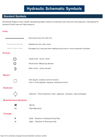
Hayward Hydraulics and Pump SizingFor Existing Pools Copyright 2011 Hayward Industries
Table of ContentsIntroductionHydraulic Terms & DefinitionsHydraulic ExampleHow To Determine GallonageTurnover RatesFriction LossTotal Dynamic HeadHow To Read Pump CurvesSpa & WaterfeaturesHow To Increase Energy EfficiencyPump Performance CurvesPage 1Pages 2-4Page 5Page 6Pages 7-8Pages 9-11Page 12Page 13Page 14Pages 15-20Pages 21-29
IntroductionHydraulicsDefinition: The branch of science concerned with the practical applications of fluids,primarily liquids, in motion. (2010 Britannica.com)Hydraulics are the bloodlines of a swimming pool’s pump & filtration system – an arterialsystem similar to the human body’s – a mechanical, pulsating system that cleanses,recycles and reliably maintains a healthy body and flow of water.This guide deals with the movement of water, and focuses on increasing yourunderstanding of the following:1.How much water do we have (pool capacity)?2.How fast can we safely move the water (Turnover Rate and Water Velocity)?3.How much resistance will this water meet while moving thru the system(Friction Loss)?4.How will we overcome this resistance (Pump Sizing)?5.How can we increase energy efficiency in regards to hydraulics and pumpselection?Page 1
Hydraulic Terms & DefinitionsGPMGallons Per MinuteTurnover RateThe amount of time required to circulate the entire volume of water through the system.Check with local regulations for the minimum required turnover rate.VelocityThe speed at which the water is flowing. Expressed in FPS or Feet Per Second. Currentrequirements:. 6 FPS Suction side (coming from pool), 8 FPS Return side (returning to pool),per APSP-7.Desired Flow rateThe flow rate between the minimum flow based on the Turnover rate and the maximum flowbased on water velocity. It is recommended to select a flow that is higher than the minimumto account for decrease in flow that naturally occurs as the filter becomes loaded with dirtand debris.Friction Head LossThe resistance to water flow, as expressed in FEET OF HEAD.Page 2
Hydraulic Terms & DefinitionsSystem Head LossWhen all system factors are added that can contribute to the resistance of flow. Alsocalled Total Feet of Head or Total Dynamic Head (TDH).Atmospheric PressurePressure caused by the weight of the atmosphere. Atmospheric pressure on the surfaceof the water is necessary for the pump to operate. At higher elevations, the pump has toproduce more vacuum to pull the water up the pipe, since there is less pressure pushingon the surface of the pool water. As we go up in elevation, this pressure decreases.Atmospheric Pressure at Sea level is 14.7 psi.For every 1000 ft of elevation 1.155 feet suction lift loss.Example: A pump that can pull 10’ suction lift at sea level can only do 8.845’ suction lift at1000’ elevation, or 4.225’ at 5000’ elevation.Static LiftDistance from the water level in the pool to the center of the impeller.Page 3
Hydraulic Terms & DefinitionsCavitationThe formation of vapor bubbles of a flowing liquid in a region where the pressureof the liquid falls below it’s vapor pressure.Common Symptoms of Cavitation A reduction in the flow of water. The formation of bubbles in a low pressure area of the pump volute. A noise that can be heard when the pump is running. Damage that can be seen on the pump impeller and volute.Example: If you have a pump that wants to pump 80 GPM, but a 1.5"suction line that will only provide 51 GPM, cavitation may occur.Page 4
ExampleThe following pages contain step-by-step instructions to answer the four questionslisted on Page 1 and ultimately determine the proper size pump for virtually anyexisting application. Example calculations are provided below each step based onthe following example: 16’ x 32’ rectangular pool, 3’ to 8’ deep 2” suction side and return side plumbing Existing 1 HP pump Filter pressure gauge reads 10 PSI (clean)Page 5
How to Determine GallonagePool TypeRectangularLength x Width x Average Depth x 7.5 pool capacity in gallonsOval:Length x Width x Average Depth x 6.9 pool capacity in gallonsRound:Length x Width x Average Depth x 5.9 pool capacity in gallonsFree Form:Divide the pool into the above shapes, then add together.Example 116’ x 32’ x 5.5’ x 7.5 21,120 gallonsAfter we know the amount of water, we can then determine what the properturnover rate must be.Page 6
Minimum Turnover RateTotal Gallons Turnover Hours 60 Minutes Minimum Turnover Rate Historically, Common turnover rates are 8-10 hours. Commercial rates vary, most common is 1 turnover in 6 hours.Example 2Gallons6 HourTurnover8 HourTurnover10 HourTurnover15,00050 GPM31 GPM25 GPM20,00067 GPM42 GPM34 GPM25,00083 GPM52 GPM42 GPM30,000100 GPM63 GPM50 GPM21,120 Gallons 8 Hours (assumed) 60 Minutes 44 GPM Minimum Turnover RatePage 7
Maximum GPM Flow RatesThe table below lists the maximum flow in GPM based on plumbing size and water velocity.APSP-7 Requires: 6 FPS Suction side, 8 FPS Return side maximum for residential pools.Pipe Size6 Ft/sec8 Ft/sec1.5”38 GPM51 GPM2”63 GPM84 GPM2.5”90 GPM119 GPM3”138 GPM184 GPMThe desired flow rate must be between the minimum turnover rate and the maximum flow rate.The average of the minimum and maximum rates is the Desired Flow Rate.Example 3Minimum Flow (Turnover Rate) 44 GPMMaximum Flow (Water Velocity) for 2” Pipe @ 6 FPS 63 GPMDesired Flow Rate 53.5 GPMPage 8
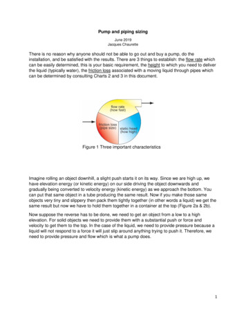
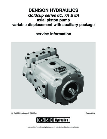
Friction LossEverything that the water must pass through within the circulation system – plumbing andequipment- creates resistance to flow or Friction Loss.A properly sized pump will have the ability to overcome the Total Dynamic Head of thesystem while, at the same time, providing flow that will satisfy Turnover Rate and WaterVelocity requirements.For new installations, it is possible to calculate the TDH by using reference tables andmanufacturer’s data to determine the friction loss associated with every component in thecirculation system.For existing installations, we will need to add the resistance from the suction side(vacuum) of the existing pump to the resistance of the return side (pressure) of the pump.Note this assumes the Static Suction Lift is offset by the water returning to the pool.Suction Side(From Pool)Return Side(To Pool)Page 9
Friction Loss – Suction SideA vacuum gauge can be used on the suction side of the system to provide avacuum reading in inches of mercury. The pump’s drain plug port that is closestto the front of the pump is an ideal place to attach the vacuum gauge.Take the vacuum reading of the pump and multiply the value by 1.13.This is the amount of Friction Loss for the suction side of the system.Example 419 inches of mercury x 1.13 21.47 ft. of water.Page 10
Friction Loss – Return SideTake the clean Filter Pressure, as measured on the filter gauge in PSI, andmultiply the value by 2.31.This is the amount of Friction Loss for the return side (pressure).Example 512 PSI x 2.31 27.72 ft. of water.Page 11
Total Dynamic HeadNow that we know the amount of resistance on the suction and pressure sides of the system,we can add these values together to find the Total Dynamic Head (TDH) for the entire system.Vacuum feet of water Pressure feet of water TDHExample 6 21.47 27.72 49.19 TDHWe now have all the information necessary to select the proper size pump.Example 7We need a pump that will provide53.5 GPM @ 49.19 TDH.Note: This only determines the TDH that the pump is producing at that specific flowrate with thecurrent state of all of the valves, etc. in the plumbing system, as well as the dirt load of the filter.This number can then be used with a performance curve to approximate the flowrate for thecurrent system condition, but any changes in valve position or filter load would change thisnumber.Page 12
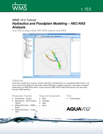
How To Read Pump Performance CurvesA pump curve has three factors:Total Feet of Head, GPM, and the actual performance curve for that pump.Knowing any two of the three variables allows you to find the third.Example 849.1953.5SP2610X15 (1.5 HP SuperPump) is one pump for our example.Page 13
Spa Turnover RatesSpa Jets normally require 10-15 GPM.Check with the manufacturer for specific flow rate requirements.The turnover rate for the pool may not be as large as the spa jet requirement.If the spa requires more than 20% of the pool turnover rate, a two pump systemshould be considered.Water Feature RatesIf the water feature(s) exceed 35 GPM, consider using a separate pump.If less than 35 GPM is required for the water feature(s), one pump may satisfy both flow rates.For new installations, remember to add all pipe and fittings of the water feature(s) to the TDHcalculations of the pool.Page 14
How To Increase Energy EfficiencyBy slowing down the speed of the water (velocity), the amount of resistance (TDH) in thecirculation system is drastically reduced.Reducing the TDH that the pump must overcome allows us to utilize smaller horsepowerpumps and/or operate pumps at lower speeds. Below is a list of benefits associated withmoving the water slower (reducing GPM flow rate).Note: If the flow rate (GPM) changes from the initial calculation, one must be carefulto consider the change in Turnover time.Benefits of Moving Water Slower1.2.3.4.5.6.Reduced TDH (lower water velocity)Reduced Energy Cost (lower kWh)Quiet operatonLess stress on the plumbing and equipmentWater is typically filtered to a smaller particle size.Better distribution of chemicals may reduce the amount of chemicals needed.Page 15
How To Increase Energy EfficiencyHow to Move Water Slower1.Pump Reduce the pump horsepower. Reduce speed of the pump to lower the GPM flow rate.2.System Increase the plumbing size and reduce the length of plumbing required. Use Fittings / elbows that account for less than resistance than others.Example: 45 elbows vs. 90 elbowsEnergy Saving Pump Types Energy efficient single speed pump offering the lowest flow required. 2-Speed PumpsVariable Speed PumpsPage 16
How To Increase Energy EfficiencyLower HP, Energy Efficient Single Speed Pump Features Low initial cost compared to multi-speed pumps. Greater efficiency verses older, higher horsepower pumpsCapacitor Start Induction Run (CSIR)Typical EfficiencyRange %40% - 55%Permanent Split Capacitor(PSC)45% - 60%Capacitor Start Capacitor Run(CSCR)55% - 75%Possible applications Pools with 1 ½ “ or 1 ¼” inch pipe Pools plumbed with Copper pipe Pools with 115 volt service only Very small pools with turnover rates under 8 hours.Page 17
How To Increase Energy Efficiency2-Speed Pump Features Utilize low speed for filtering, high speed for cleaning, spa use, etc. Controllers can be utilized to automatically switch from high speed to low speed. Excellent energy savings potential2 Speed Pump Applications Customers wanting more energy savings than offered by single speed pumps. Pool & Spa Combo with 2” plumbing lines. Applications in areas that require multi-speed pumps by law.Page 18
How To Increase Energy EfficiencyVariable Speed Pump Features Complete control of the pump operating speed. Ability to tailor the pump speed to specific applications. Highest energy savings potential of the three pump types.Variable Speed Pump Applications Applications needing three or more speeds (spas, water features, etc.) New pools where pipe size can be controlled.Pools with small diameter plumbing that do not require higher speed settings. When application calls for highest energy efficiency.Page 19
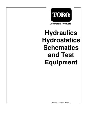
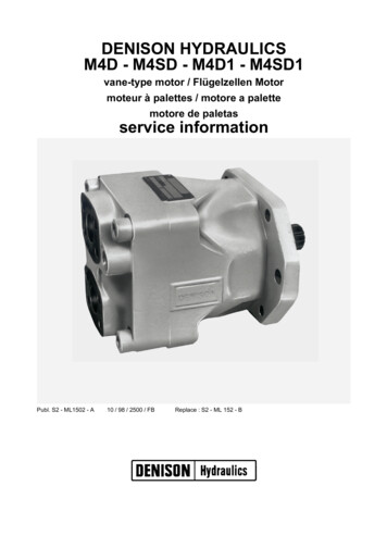
How To Increase Energy EfficiencyFor existing applications Replace pump and other older, less efficient equipment with more new, moreefficient models. Increase pipe size wherever possible thus reducing restriction to flow (TDH). Replace all 90 elbows with more efficient 45’s or short or long radius sweeps. Make sure the suction line to the pump is 4 to 6 times the pipe size diameter inlength to help prevent cavitation. For example: If plumbing is 2”, you should have8” –12” of straight pipe after the last turn and before the pump.12”Page 20
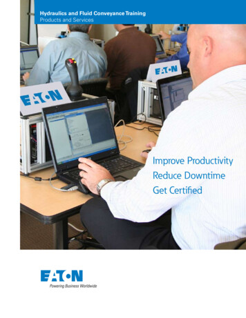
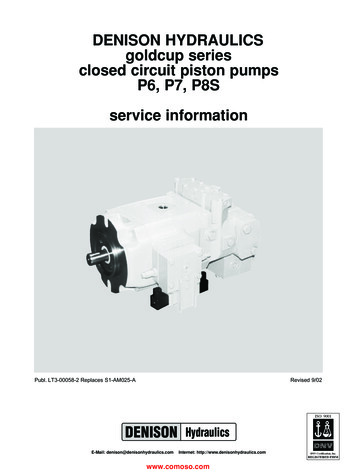
EcoStar Performance CurvePage 21
TriStar EE Full Rate Performance CurvePage 22
TriStar SE Max Rate Performance CurvePage 23
NorthStar Performance CurvePage 24
TriStar Waterfall Performance CurvePage 25
Super II Performance CurvePage 26
Super Pump Performance CurvePage 27
Max-Flo II Performance CurvePage 28
Max-Flo Performance CurvePage 29
Hydraulics are the bloodlines of a swimming pool’s pump & filtration system – an arterial system similar to the human body’s – a mechanical, pulsating system that cleanses, recycles and reliably maintains a healthy body and flow of water. This guide deals with the movement of water, and focuses on increasing your understanding of the following: 1. How much water do we have (pool .