Transcription
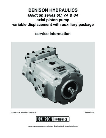
DENISON HYDRAULICSGoldcup series 6C, 7A & 8Aaxial piston pumpvariable displacement with auxiliary packageservice informationS1-AM007-B replaces S1-AM007-AInternet: http://www.denisonhydraulics.com E-mail: denison@ denisonhydraulics.comRevised 5/02
CONTENTSPAGEtypical -3fluid -------------------------5start up omparison of solid contamination classification ------6assembly tool 0rework of wear 12drive shaft & ------------------------------------------12barrel & auxiliary drive -----------------------------12cam/cradle /shoe/retainer ------------------------------13rocker cam, pistons & ------------------------------14mtg. flg./cradle/barrel/aux. shaft -----------------16housing g./end cap/cam/barrel -------------------------17port block ting port block to housing ----------------18gerotor & barrel ------------------------------------19valve block assembly (before ---------------------22valve block assembly (after -----------------------24valve block assembly for special mounting of servovalve (before 7-93)-------------------28valve block assembly for special mounting of servovalve (after 7-93)---------------------30shaft & seal erbalance servo stem -----------------------35control cover ctions for replenishing isolation -----------36gage --37P*P,P*D test procedure ------------------------------38P*V test procedure ------------------------------------40basic pump installation ---------------------------42technical data --------------------------------------44pump key al kits (see key sheet pg. 45 for information)pump complete less controlsvalve blockhi-iq valve blockshaft seal kit, SAE 127-2 mtg.shaft seal, SAE 127-2 mtg.shaft seal, SAE 152-4 3-00006623-00016S23-02303NOTE: New revisions are shown underlined. Pages are marked Revised wherechanges have been made.2 Revised
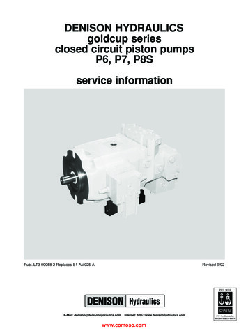
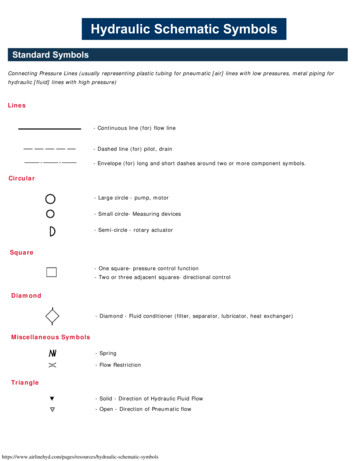
INSTALLATIONSpecificationTYPICAL CHARACTERISTICSFLUID CONNECTIONSFAHVAAGAVKTerm3Goldcup 6Goldcup 7Goldcup 8 displacement at max. anglein /rev.cm3/rev.6.0098,37.25118,88.00131 pressure continuouspsibar500034550003453600250 pressure intermittentpsibar600041460004144500310 speed, max. continuousRPM300030001800 flow, ports A or B @1800 RPM(theoretical)GPMl/min.46.817756.5213,862.3235,8 flow, repl. pump @ 1800 RPM(theoretical)GPMl/min.8.3331,68.3331,68.3331,6 servo pressure-closed circuitpsibar335-53523-37335-53523-37335-53523-37 servo pressure -open circuitpsibar150-52510-35150-52510-35150-52510-35 mounting-flangeSAE shaft-keyedSAE32-1, 44-1(C, D)32-1, 44-1(C, D)32-1, 44-1(C, D) shaft-splinedSAE32-4, 44-4(C, D)32-4, 44-4(C, D)32-4, 44-4(C, D) weight w/spg. ctd. rotary servolbs.kg.175791757917579 port A -closed circuit (system)SAE code 62 split flangein.mm1-1/238,11-1/238,11-1/238,1 port A -open circuit (inlet)SAE code 61 split flangein.mm250,8250,8250,8 port B (system)SAE code 62 split flangein.mm1-1/238,11-1/238,11-1/238,1 port AG,BG (A&B system gage)SAEstraight thread O-ring seal-6-66 port C (aux. pump inlet)straight thread O-ring sealSAE-16-16-16 port D1,D2 (case drains)straight thread O-ring sealSAE-12-12-12 port DG (case gage)straight thread O-ring sealSAE-6-6-6 port FA,FB (control pressures)drysealNPTF1/4”1/4”1/4” port G (aux. pump outlet)port H (aux. flow return)straight thread O-ring sealSAE-8-8-8 port K (aux. repl inlet)straight thread O-ring sealSAE-16-16-16 port KG (repl. gage)straight thread O-ring sealSAE-6-6-6 port V (common vent)port VA,VB (A&B side vents)straight thread O-ring sealSAE-4-4-4 port DG2 (case)straight thread O-ring sealSAE-4-4-4127-2, 152-4 127-2, 152-4 127-2, 152-4(C, D)(C, D)(C, D)KGBVBFBGDGD1DG2D2C3 RevisedBG
INSTALLATIONINTRODUCTIONThe DENISON HYDRAULICS Goldcup 6, Goldcup 7 and Goldcup 8 axial piston pumpsfeature advance design concepts which are time proven and provide for advance pumping and control concepts. The instructions contained in this manual cover complete disassembly and re-assembly of the unit. Before proceeding with the disassembly or reassembly of any unit, this manual should be studied in order to become familiar withproper order and parts nomenclature.DESCRIPTIONThe use of a rocker cam to control the pump displacement provides a small packagesize, reduces wear, and speeds control response. The control vane actuator eliminateslinkage and backlash inherent in typical stroking cylinder designs.Standard controls for the Goldcup units are rotary servo and compensator over-ride.Additional optional controls are also available.MOUNTINGThis pump is designed to operate in any position The mounting hub and two bolt mounting flange are in full conformance with SAE standard. The pump shaft must be in alignment with the shaft of the driving load and should be checked with a dial indicator. Themounting pad or adapter into which the fluid pump pilots must be concentric with thepump shaft to prevent bearing failure. This concentricity is particularly important if theshaft is rigidly connected to the driving load without a flexible coupling.SHAFT INFORMATIONSplined: The shafts will accept a maximum misalignment of .006” TIR, 0,15 mm. Angularmisalignment at the male and female spline axes must be less than .002” per inchradius, 0,002 mm per mm radius. The coupling interface must be lubricated. DENISONHYDRAULICS recommends lithium- molybdenum disulfide or similar grease. Thefemale coupling should be hardened to 27-45 Rc and must conform to SAE-J498B(1971) class 1 flat root side fit.Keyed: High strength heat treated keys must be used. Replacement keys must be hardened to 27-34 Rc. The key corners must be chamfered .03”-.04”, 0,75-1 mm at 45 toclear radii that exist in the keyway.SIDE LOADC- flange pumps will accept a side load of 170 lb., 77 kg, and D- flange pumps willaccept a side load of 215 lb, 97 kg, at the center of the spline or key, with a B10 life of10000 hours at 1800 RPM.PIPINGConnect inlet and outlet lines to the port block of the pump.The maximum case pressure is 75 PSI, 5,7 bar continuous, 125 PSI, 8,6 bar intermittent. Case pressures must never exceed inlet pressure by more than 25 PSI, 1,7 bar.When connecting case drain line make certain that drain plumbing passes above highest point of the pump before passing to the reservoir. If not, install a 5 PSI, 0,3 bar casepressure check valve to be certain the case is filled with oil at all times.The case leakage line must be of sufficient size to prevent back pressure in excess of75 PSI, 5,7 bar and returned to the reservoir below the surface of the oil as far from thesupply suction as possible. All fluid lines, whether pipe, tubing, or hose must be adequate size and strength to assure free flow through the pump. An undersize inlet line willprevent the pump from operating at full rated speed. An undersize outlet line will createback pressure and cause heat generation. Flexible hose lines are recommended. If rigidpiping is used, the workmanship must be accurate to eliminate strain on the pump portblock or to the fluid connections. Sharp bends in the lines must be eliminated whereverpossible. All system piping must be cleaned with solvent or equivalent before installingpump. Make sure the entire hydraulic system is free of dirt, lint, scale, or other foreignmaterial.CAUTION: Do not use galvanized pipe. Galvanized coating can flake off withcontinued use.SERVICE INFORMATIONThese hydraulic products are designed to give long dependable service when properlyapplied and their systems properly maintained. These general instructions apply to typical systems. Specific instructions for particular equipment can be developed from them.RECOMMENDED FLUIDSThe fluid recommended for use in these pumps and motors has a petroleum base andcontains agents which provide oxidation inhibition and anti-rust, anti-foam and de-aerating properties as described in DENISON HYDRAULICS standard HF-1. Where antiwear additive fluids are specified, see DENISON HYDRAULICS standard HF-0.4 Revised
INSTALLATIONVISCOSITYMax. at cold start - 7500 SUS, 1600 Cst(at low pressure, low flow, and if possible, low speed)Max. at full power - 750 SUS, 160 CstOptimum for max. life - 140 SUS, 30 CstMinimum at full power - 60 SUS, 10 CstVISCOSITY INDEX90 V.I. minimum. Higher values extend the range of operating temperature but mayreduce the service life of the fluid.TEMPERATUREDetermined by the viscosity characteristics of the fluid used. Because high temperaturesdegrade seals, reduce the service life of the fluid and create hazards, fluid temperaturesshould not exceed 180 F, 82 C at the case drain.ALTERNATE FLUIDSSome applications require fire-resistant fluids. They will give good service if the systemis originally designed for their use. Permissible fire resistant fluids include:TypeWater-in-oil invert emulsionsWater glycol solutionsPhosphate estersDENISON HYDRAULICS StandardHF-3HF-4HF-5Consult DENISON HYDRAULICS for design requirements and warranty limitations forservice with this class of fluids.See DENISON HYDRAULICS bulletin SPO-AM305 for more information.FILLING CASEIt is essential to make certain that the case (pump housing) is as full of fluid as possibleand remains full during operation and at rest.Always fill to the highest available point. Remove a plug or screw and allow the oil toescape through this point.Recommended fill points:Mounting orientation vertical, shaft up. D1 or D2 (drain) port in housingVent DG2 port in mounting flange (new units) orone of the upper screws which attach the control. See installation drawing.Vertical, shaft down 1) or horizontaldrain ports to the side.D1 or D2 (drain port in housing.1) Vent DG (case gage) port in port block.MAINTENANCEThis pump is self-lubricating and preventative maintenance is limited to keeping systemfluid clean by changing filters frequently. Keep all fittings and screws tight. Do not operate at pressures and speeds in excess of the recommended limit. If the pump does notoperate properly, check the troubleshooting chart before attempting to overhaul the unit.Overhauling is relatively simple and may be accomplished by referring to the disassembly, rework limits of wear parts, and assembly procedures.FLUID CLEANLINESSFluid must be cleaned before and continuously during operation, by filters that maintain acleanliness level of NAS 1638 class 8 (class 9 for 15 micron and smaller). This approximately corresponds to ISO 17/14. This fluid level cleanliness can usually be accomplished by the effective use of 10 micron filters. Better cleanliness levels will significantlyextend the life of the components. As contaminant generation may vary with each application, each must be analyzed to determine proper filtration to maintain the requiredcleanliness level.START UP PROCEDURES FORNEW INSTALLATION Read and understand the instruction manual. Identify components and their function. Visually inspect components and lines for possible damage. Check reservoir for cleanliness and drain and clean as required. Check fluid level and fill as required with filtered fluid at least as clean as that recommended. Fill pump case with clean oil prior to starting. Check alignment of drive. Check oil cooler and activate it, If included in circuit. Reduce pressure settings of relief valve. Make sure accurate pressure readings canbe made at appropriate places. If solenoids are included in system, check for actuation. Start pump drive. Make sure pump and motor fill properly. Bleed system of air. Re-c
The DENISON HYDRAULICS Goldcup 6, Goldcup 7 and Goldcup 8 axial piston pumps feature advance design concepts which are time proven and provide for advance pump-ing and control concepts.The instructions contained in this manual cover complete dis-assembly and re-assembly of the unit.Before proceeding with the disassembly or re-