Transcription
RS485 & Modbus Protocol GuideProducts Covered Quadratic Integra 1000 Switchboard Integra 1000 Integra 1540 Integra 1560 Integra 1580 Quadratic Integra 2000 System Protection Relay (SPR)Tyco Electronics UK LimitedCrompton InstrumentsFreebournes Road, Witham, Essex, CM8 3AH, UKTel: 44 1376 509 509Fax: 44 1376 509 511
The Information contained in this guide is for use only by installers trained to make electrical power & communications installations and is intended to describe thecommuications function of the products covered. However, Tyco Electronics has no control over the field conditions which influence product installation.It is the user's responsibility to determine the suitability of the installation method in the user's field conditions. Tyco Electronics' only obligations are those in TycoElectronics' standard Conditions of Sale for this product and in no case will Tyco Electronics be liable for any other incidental, indirect or consequential damagesarising from the use or misuse of the products. Crompton is a trade mark.Tyco Electronics UK LimitedCrompton InstrumentsFreebournes Road, Witham, Essex, CM8 3AH, UK2 of50935 509 Fax: 44 1376 509 511Phone:Page 44 1376http://energy.tycoelectronics.comRS485Guide 07/02 Rev 6
Introducing the MODBUS ProtocolThis document is intended to provide an introduction to the MODBUS implementation of Integra and SPRproducts. The document was generated in response to repeated questions from the field. The section atthe end of the document, “When things go wrong”, identifies a number of potential problems some ofwhich have been experienced in the field.The MODBUS protocol “defines a message structure that controllers will recognise and use, regardless ofthe type of networks over which they communicate. It describes the process a controller uses to requestaccess to another device, how it will respond to requests from the other devices, and how errors will bedetected and reported. It establishes a common format for the layout and contents of message fields.” Modbus Protocol Reference Guide, PI-MBUS-300 Rev. J. This document may be purchased from“Groupe Schneider, Basingstoke, England 44 (0) 1256 843184.There are a number of hardware configurations used for MODBUS networks, this guide will consider onlythe two wire RS485 network as that is the configuration currently supported by the SPR and Integra familyof products.MODBUS is a trademark of AEG Schneider Automation IncPage 3 of 35RS485 Guide 07/02 Rev 6
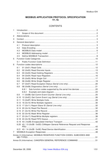
ContentsINTRODUCING THE MODBUS PROTOCOL.3CONTENTS .4WHAT IS RS485?.5WHAT IS HALF DUPLEX?.5CONNECTING THE INSTRUMENTS .5WHICH IS A AND WHICH IS B? .6MODBUS MESSAGES.7MODBUS MESSAGE FORMAT .7THE SERIAL TRANSMISSION MODES .9ASCII MODE .9RTU MODE .10MODBUS MESSAGE TIMING (RTU MODE).10HOW CHARACTERS ARE TRANSMITTED SERIALLY .11ERROR CHECKING METHODS .11PARITY CHECKING .12FUNCTION CODES.13PRODUCT SPECIFIC CONSIDERATIONS. .13MODBUS COMMANDS SUPPORTED .15READ INPUT REGISTERS .15READ HOLDING REGISTERS .16WRITE HOLDING REGISTERS .17DIAGNOSTICS .18WHEN THINGS GO WRONG.19PRODUCT INFORMATION .20EXCEPTION CODES.20START UP CONSIDERATIONS. .20IDENTIFYING IMPORTING, EXPORTING, LEADING AND LAGGING.21LINE TO LINE AND LINE TO NEUTRAL VOLTAGES: .21INSTRUMENT MODBUS REGISTERS .21INPUT REGISTERS .21HOLDING REGISTERS .22HOLDING REGISTERS SPECIFIC TO THE 1560 /1580 .22HOLDING REGISTER SPECIFIC TO THE SPR .25APPENDIX A: INSTRUMENT INPUT REGISTERS .29APPENDIX B: INSTRUMENT HOLDING REGISTERS .34Page 4 of 35RS485 Guide 07/02 Rev 6
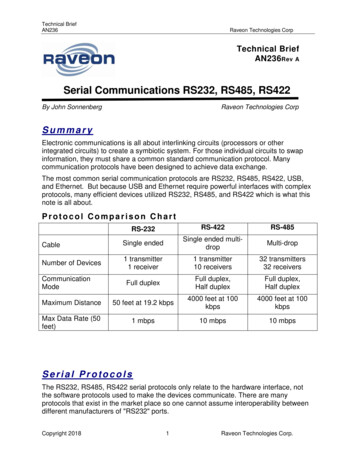
What is RS485?RS485 or EIA (Electronic Industries Association) RS485 is a balanced line, half-duplex transmissionsystem allowing transmission distances of up to 1.2 km. The following table summarises the RS-485Standard:PARAMETERMode of OperationDifferentialNumber of Drivers and Receivers32 Drivers,32 ReceiversMaximum cable length (metres)1200Maximum data rate (baud)10 MMaximum common mode voltage (Volts)12 to -7Minimum Driver Output Levels (Loaded) /- 1.5Minimum Driver Output Levels(Unloaded) /- 6Drive Load (Ohms)60 (min)Driver Output short circuit current Limit(mA)150 to Gnd, 250 to -7 or 12 VMinimum receiver input Resistance(kohms)12Receiver sensitivity /- 200mvFurther information relating to RS485 may be obtained from either the EIA or the various RS485 devicemanufacturers: Texas Instruments Maxim SemiconductorsWhat is half duplex?Half duplex is a system in which one or more transmitters (talkers) can communicate with one or morereceivers (listeners) with only one transmitter being active at any one time. For example, a “conversation”is started by asking a question, the person who has asked the question will then listen until he gets ananswer or until he decides that the individual who was asked the question is not going to reply.In a 485 network the “master” will start the “conversation” with a “Query” addressed to a specific “slave”,the “master” will then listen for the “slave’s” response. If the “slave” does not respond within a pre-definedperiod, (set by control software in the “master”), the “master” will abandon the “conversation”.Connecting the InstrumentsScreened twisted pair cable should be used. All “A” connections should be connected together using oneconductor of the twisted pair cable, all “B” connections should be connected together using the otherconductor in the pair. The cable screen should be connected to the “Gnd” terminal.Page 5 of 35RS485 Guide 07/02 Rev 6
A Belden 9841 (Single pair) or 9842 (Two pair) cable with a characteristic impedance of 120 ohms isrecommended, the cable should be terminated at each end with a 120 ohm, quarter watt (or greater)resistor.There must be no more than two wires connected to each terminal, this ensures that a “Daisy Chain or“straight line” configuration is used. A “Star” or a network with “Stubs (Tees)” is not recommended asreflections within the cable may result in data corruption.Which is A and Which is B?The A and B connections to the SPR and Integra Products can be identified by the signals present onthem whilst there is activity on the RS485 bus:Page 6 of 35RS485 Guide 07/02 Rev 6
MODBUS MessagesCommunication on a MODBUS Network is initiated (started) by a “Master” with a “query” to a “Slave”. The“Slave “ which is constantly monitoring the network for “Queries” will recognise only the “Queries”addressed to it and will respond either by performing an action (setting a value for example) or byreturning a “response”. Only the Master can initiate a query.In the MODBUS protocol the master can address individual slaves, or, using a special “Broadcast”address, can initiate a broadcast message to all slaves. The SPR and Integra products do not support thebroadcast address.MODBUS Message FormatThe MODBUS protocol defines the format for the master’s query and the slave’s response.The query contains the device (or broadcast) address, a function code defining the requested action, anydata to be sent, and an error-checking field.The response contains fields confirming the action taken, any data to be returned, and an error-checkingfield. If an error occurred in receipt of the message, or if the slave is unable to perform the requestedaction, the slave will construct an error message and send it as its response.QueryThe example illustrates a request for a single 16-bit Modbus tartAddress(Lo)Numberof Points(Hi)Numberof Points(Lo)ErrorCheck(Lo)ErrorCheck(Hi)Slave Address:8-bit value representing the slave being addressed (1 to 247), 0 is reserved forthe broadcast address. The SPR and Integra products do not support thebroadcast address.Function Code:8-bit value telling the addressed slave what action is to be performed. (3, 4, or16 are valid for Integra)Start Address (Hi):The top (most significant) eight bits of a 16-bit number specifying the startaddress of the data being requested.Start Address (Lo):The bottom (least significant) eight bits of a 16-bit number specifying the startaddress of the data being requested.Page 7 of 35RS485 Guide 07/02 Rev 6
Number of Points (Hi): The top (most significant) eight bits of a 16-bit number specifying the number ofregisters being requested.Number of Points (Lo): The bottom (least significant) eight bits of a 16-bit number specifying the numberof registers being requested.Error Check (Lo):The bottom (least significant) eight bits of a 16-bit number representing the errorcheck value.Error Check (Hi):The top (most significant) eight bits of a 16-bit number representing the errorcheck value.ResponseThe example illustrates the normal response to a request for a single 16-bit Register.SlaveAddressFunctionCodeByteCountData (Hi)Data(Lo)ErrorCheck(Lo)ErrorCheck(Hi)Slave Address:8-bit value representing the address of slave, which has just responded.Function Code:8-bit value which, when a copy of the function code in the query, indicates thatthe slave recognised the query and has responded. (See also ExceptionResponse).Byte Count:8-bit value indicating the number of data bytes contained within this responseData (Hi):The top (most significant) eight bits of a 16-bit number representing theregister(s) requested in the query.Data (Lo):The bottom (least significant) eight bits of a 16-bit number representing theregister(s) requested in the query.Error Check (Lo):The bottom (least significant) eight bits of a 16-bit number representing the err
RS485 or EIA (Electronic Industries Association) RS485 is a balanced line, half-duplex transmission system allowing transmission distances of up to 1.2 km. The following table summarises the RS-485 Standard: PARAMETER Mode of Operation Differential Number of Drivers and Receivers 32 Drivers, 32 Receivers Maximum cable length (metres) 1200 Maximum data rate (baud) 10 M Maximum common