Transcription
ImplementingRS-485 on AVRKhalate Sumant14th July, 2011
ContentsIContent1 Introduction1.1 Overview . . . . . . . . . .1.2 Requirements . . . . . . .1.3 Limitations . . . . . . . .1.4 Handshaking . . . . . . .1.5 Termination . . . . . . . .1.6 Pin labeling . . . . . . . .1.7 RS485 in Real World . . .1.8 Waveform example . . . .1.9 Differences between RS2322. . . . . . . . . . . . . . . . . . . . . . . . . . . . . . . . . . . . . . . . . . . . . . . . .and RS485.33444556672 Characteristics of RS48583 MAX485 IC94 Hardware114.1 Single Master and Slave . . . . . . . . . . . . . . . . . . . . . 114.2 Multi Master and Slave . . . . . . . . . . . . . . . . . . . . . . 13IIDatasheet15MAX485 . . . . . . . . . . . . . . . . . . . . . . . . . . . . . . . . . 16I
List of Figures1.1Waveform of 0xD3 transmitted on RS485 . . . . . . . . . . .3.1Pinout diagram of MAX485 and its connection . . . . . . . . 104.14.2Simple RS485 Communication . . . . . . . . . . . . . . . . . . 12Multi Master-Slave RS485 Communication . . . . . . . . . . . 1317
Part IContent2
Chapter 1IntroductionRS485 is the physical layer for many higher-level protocols, includingModbus 1 , Profibus 2 and other Fieldbus 3 systems, SCSI-2, SCSI-3, and BitBus. Unlike RS232, which has a transmit wire and a receive wire, RS485has a transmit wire pair. Typically one wire is labelled A and the other islabelled B, and the wires are twisted together (twisted pair). This allowsRS485 to transmit over much longer distances, using equivalent wires andequivalent transmitters and receivers, than RS232. Many RS485 implementations use 2 wires (1 pair). At all times, at most one device is transmitting onthe pair, and all the other devices on the network are listening (half-duplex).It is the responsibility of user software to ensure that several different devicesdon’t try to transmit at the same time, this can be a tricky coordination task.1.1OverviewRS485 only specifies electrical characteristics of the driver and the receiver.It does not specify or recommend any communications protocol. RS485 enables the configuration of inexpensive local networks and multi-drop communications links. It offers data transmission speeds of 35 Mbit/s up to 10m and 100 kbit/s at 1200 m. Since it uses a differential balanced line overtwisted pair (like RS422), it can span relatively large distances (up to 4,000feet (1,200 m)). A rule of thumb is that the speed in bit/s multiplied by thelength in meters should not exceed 108. Thus a 50 meter cable should notsignal faster than 2 Mbit/s.1It is a protocol developed by Modicom.It is another protocol developed by BMBF (German department of education and research)3Protocol developed by23
1.2. REQUIREMENTSThe recommended arrangement of the wires is as a connected seriesof point-to-point (multi-dropped) nodes, a line or bus, not a star, ring, ormultiply connected network. Ideally, the two ends of the cable will have atermination resistor connected across the two wires. Without terminationresistors, reflections of fast driver edges can cause multiple data edges thatcan cause data corruption. Termination resistors also reduce electrical noisesensitivity due to the lower impedance, and bias resistors are required. Thevalue of each termination resistor should be equal to the cable impedance(typically, 100 ohms for twisted pairs).1.2RequirementsA full-duplex RS485 system requires 3 twisted pairs, 2 twisted pairs for signalling, and another conductor for ground. This so-called four-wire RS485system requires 5 wires. A half-duplex system only requires 2 twisted pairsone twisted pair for signalling, and another conductor for ground. This socalled two-wire RS485 system requires 3 wires.The ground conductor can be eliminated in some cases, but it is safe tostick to Three wire system.1.3LimitationsStandard RS485 is limited to a maximum speed of 35 Mbps with a networklength of 12 meters, and 100 Kbps with a network length of 1200 meters.With interface devices that exceed standards and careful network design,higher throughput over longer cables is possible.With the use of Shielded twisted pair (STP) or Foiled twisted pair (FTP)cable the throughput can be increased even more.1.4HandshakingThere is no hardware handshaking in RS485. If handshaking is requiredfor RS485 it can be done using X-On / X-Off handshaking protocol. TheRS485 standard originally used half-duplex communication and handshakingsignals such as RTS / CTS to control the direction of data flow. Many USBto serial converters come with ADDC (Automatic Data Direction Control )to automatically sense and control data direction, making the handshakingsignal method obsolete.4
1.5. TERMINATION1.5TerminationPerhaps the most controversial part of RS485 is what to do at the end ofthe line. There are a wide variety of popular techniques, each of which worksgreat under one narrow range of conditions. Unterminated: This is the simplest system, but only works if boththe data rate and length are low enough. A good guideline for when itcan be used is to keep the product of the data rate (in baud) and thelongest end-to-end cable length below four hundred thousand. Numberof transmitters / receivers aren’t important (just keep them withinRS485 specification). This is the only case where a star bus topologyworks reliably. One-way resistor termination: Only works if there is only onetransmitter, which must be at the opposite end (from the resistor)of a linear bus. Two-way resistor termination: Only works with a linear bus, butallows transmitters only at the endpoints of the bus. AC termination: While AC termination may work well on backplanes, others discourage its use on RS485 lines: ”In practice, I havenever seen it”1.6Pin labelingThe EIA-485 differential line consists of two pins: A aka – aka TxD–/RxD– aka inverting pin B aka aka TxD /RxD aka non-inverting pin SC aka G aka reference pinThe SC line is the optional voltage reference connection. This is thereference potential used by the transceiver to measure the A and B voltages.The B line is positive (compared to A) when the line is idle (i.e, data is 1).In addition to the A and B connections, the EIA standard also specifies athird interconnection point called C, which is the common signal referenceground. These names are all in use on various equipment, but the actualstandard released by EIA only uses the names A and B.5
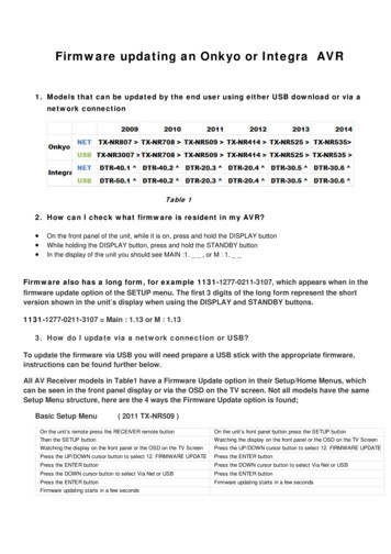
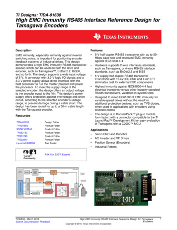
1.7. RS485 IN REAL WORLDHowever, despite the unambiguous standard, there is much confusionabout which is which, The EIA-485 signaling specification states that signalA is the inverting or 0 0 pin and signal B is the non inverting or 0 0 pin.This is in conflict with the A/B naming used by a number of differentialtransceiver manufacturers, including, among others. Texas Instruments, as seen in their application handbook on EIA422/485 communications (A non-inverting, B inverting). Intersil, as seen in their data sheet for the ISL4489 transceiver. Maxim, as seen in their data sheet for the MAX485 transceiverThese manufacturers are incorrect, but their practice is in widespreaduse. Therefore, care must be taken when using A/B naming.1.7RS485 in Real WorldNow being used commonly in the pro audio industry to control digital audioand signal processors such as the DBX driverack and other manufacturersequivalent products. Preferred to RS232 due to cheaper cabling run costsand the common availability of cables (similar to RJ-45 ). When wiring aRS485 network, always connect A to A, B to B, and G to GMany people recommend writing prototype software as if it will be connected to a half-duplex RS485 network. Then the software will work unchanged when connected to a full-duplex RS485 network, a RS232 network,and a variety of other communication media.Many people recommend wiring things up on a prototype with Category-5cable connected as point-to-point full-duplex RS485. The CAT-5 cable allowsyou to relatively quickly switch to half-duplex RS485, or the 3 wires of RS232,or a variety of other communication protocols without pulling any new cables.The point-to-point full-duplex RS485 network allows you to get the completeprototype system fully operational quickly, since it is easier to debug andmore immune to certain common problems on other systems (noise problemson RS232, turn-around problems on half-duplex RS485, etc.).1.8Waveform exampleThe image below shows potentials of the 0 0 and 0 0 pins of an EIA-485line during transmission of one byte (0xD3, least significant bit first) of datausing an asynchronous start-stop method.6
1.9. DIFFERENCES BETWEEN RS232 AND RS485Figure 1.1: Waveform of 0xD3 transmitted on RS4851.9Differences between RS232 and RS485 RS232 signal levels are typically -12 V to 12 V relative to the signalground. RS485 signal levels are typically 0 to 5 V relative to the signal ground. RS232 uses point-to-point unidirectional signal wires: There are onlytwo devices connected to a RS232 cable. The TxD output of a firstdevice connected to the RxD input of a second device, and the TxDoutput of the second device connected to the RxD input of the firstdevice. In a RS232 cable, data always flows in only one direction onany particular wire, from TxD to RxD. RS485 typically uses a linear network with bidirectional signal wires:There are typically many devices along a RS485 shared cable. TheA output of each device is connected to the A output of every otherdevice. In a RS485 cable, data typically flows in both directions alongany particular wire, sometimes from the A of the first device to theA of the second device, and at a later time from the A of the seconddevice to the A of the first device.7
Chapter 2Characteristics of RS485DescriptionModeMax number of driversMax number of receiversMode of operationNetwork topologyMax distance (acc. standard)Max speed at 12 mMax speed at 1200 mReceiver input resistanceDriver load impedanceReceiver input sensitivityReceiver input rangeMax driver output voltageMin driver output voltage (with load)8RS485Differential3232Full Duplex or Half DuplexMulti-Drop1200m (4000ft)35 Mbs100 kbs 12Ω54Ω 200mV-7.12V-7.12V1.5V
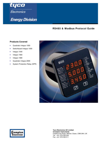
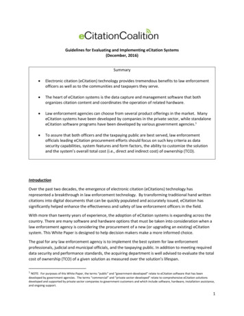
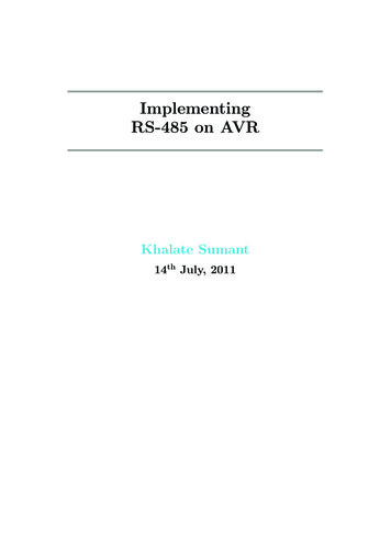
Chapter 3MAX485 ICThe MAX485 IC are low-power transceivers for RS-485 and RS- 422communication. Each part contains one driver and one receiver. The driverslew rates of the IC are not limited, allowing them to transmit up to 2.5Mbps.These transceiver draw between 120µA and 500µA of supply current whenunloaded or fully loaded with disabled drivers. Drivers are short circuitedprotected against excessive power dissipation by thermal shut-down circuitrythat places the driver output into High-impedance state. The receiver inputhas a fail-safe feature that guarantees a logic-high output if the input is opencircuit.The serial data on DI pin is transmitted on the bus and the data on busis received on RO pin. The direction of data on bus is controlled by RE andDE pins, these pins are connected together and eventually connected to thecontrol device. When RE and DE is low, data on the bus is received on RO. When they are high the data on DI, is transmitted on bus.9
MAX 485MAX 485Figure 3.1: Pinout diagram of MAX485 and its connection10
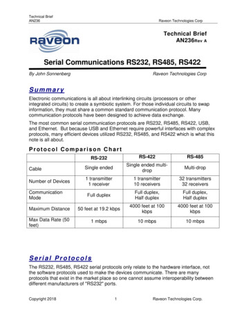
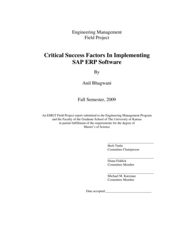
Chapter 4HardwareTo build the hardware you will require the following things.1. ATmega32 (AVR Family Micro-controller)2. MAX-4853. Twisted Pair Cable4.1Single Master and SlaveFirst we will build a simple hardware with one master and one slave,following are the instructions to building the hardware. First connect the RO pin of MAX485 to RxD pin of ATmega32, thenfollowed by DI pin to TxD pin. Connect the RE & DE pins of MAX485 to anyone i/o pin of ATmega32. Build the same hardware, as stated above and connect it to other side(i.e slave) side.11
4.1. SINGLE MASTER AND SLAVEThe following schematic shows you how to build thehardware1100E100EFigure 4.1: Simple RS485 Communication1The RO and DI pins MAX-485 pins are TTL compatible and not RS23212
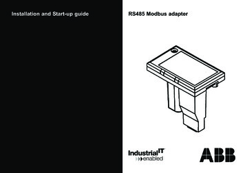
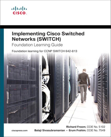
4.2. MULTI MASTER AND SLAVE4.2Multi Master and SlaveAfter you have done with simple point-to-point system, you can try complex systems with multi master and slave. In this section I have providedan example for two master and two slaves.100E.100E1212Figure 4.2: Multi Master-Slave RS485 Communication13
Reference WikipediaPowred by: LATEX 2εAuthor: Khalate Sumant14
Part IIDatasheet15
MAX 48516
19-0122; Rev 7; 6/03Low-Power, Slew-Rate-LimitedRS-485/RS-422 TransceiversThe MAX481, MAX483, MAX485, MAX487–MAX491, andMAX1487 are low-power transceivers for RS-485 and RS422 communication. Each part contains one driver and onereceiver. The MAX483, MAX487, MAX488, and MAX489feature reduced slew-rate drivers that minimize EMI andreduce reflections caused by improperly terminated cables,thus allowing error-free data transmission up to 250kbps.The driver slew rates of the MAX481, MAX485, MAX490,MAX491, and MAX1487 are not limited, allowing them totransmit up to 2.5Mbps.These transceivers draw between 120µA and 500µA ofsupply current when unloaded or fully loaded with disableddrivers. Additionally, the MAX481, MAX483, and MAX487have a low-current shutdown mode in which they consumeonly 0.1µA. All parts operate from a single 5V supply.Drivers are short-circuit current limited and are protectedagainst excessive power dissipation by thermal shutdowncircuitry that places the driver outputs into a high-impedance state. The receiver input has a fail-safe feature thatguarantees a logic-high output if the input is open circuit.The MAX487 and MAX1487 feature quarter-unit-loadreceiver input impedance, allowing up to 128 MAX487/MAX1487 transceivers on the bus. Full-duplex communications are obtained using the MAX488–MAX491, whilethe MAX481, MAX483, MAX485, MAX487, and MAX1487are designed for half-duplex applications.Features In µMAX Package: Smallest 8-Pin SO Slew-Rate Lim
RS485 network, always connect Ato A, Bto B, and Gto G Many people recommend writing prototype software as if it will be con-nected to a half-duplex RS485 network. Then the software will work un-changed when connected to a full-duplex RS485 network, a RS232 network, and a variety of other communication media. Many people recommend wiring things up on a prototype with Category-5