Transcription
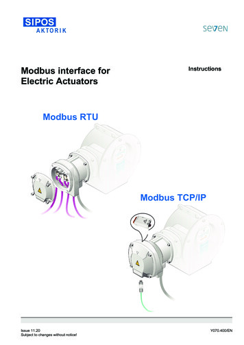
Modbus interface forElectric ActuatorsInstructionsModbus RTUModbus TCP/IPIssue 11.20Subject to changes without notice!Y070.400/EN
ContentsPage1General information31.11.2Safety instructions: Used symbols and their meaningsNotes to the operation instructions332The Modbus interface for SEVEN32.12.22.3General descriptionModbus interfaceModbus – Basic functions3443Technical Data73.13.2SEVEN with Modbus interfaceGeneral data of the Modbus interface7113.3Connection to the fieldbus system124Setting the communication parameters for Modbus144.14.2Communication parameters for ModbusOptions / tools for setting14145Using actuators with Modbus interface155.15.25.3Control via ModbusInhibiting of the local control unitFault messages on display1515156Broadcast mode and safety functions166.16.2Broadcast messagesModbus safety functions16167Redundancy for Modbus RTU168Connection status and fault signal178.18.2Connection statusBus communication fault/checksum .3.2Telegram structureMessage frame for communication via ModbusThree PDU types – communication procedureData modelFunction codes – supported servicesModbus RTU interfaceModbus TCP/IP interface (based on Modbus RTU)Modbus RTUModbus TCP/IP4556611111213Attachments Page 2Input RegistersHolding RegistersDiscretes InputCoilsTelegrams„Read Exception-Status“,„Report-Slave ID“ and„Read Device Identification“18-2425-34353637Y070.400/EN
1General information1.1Safety instructions: Used symbols and their meaningsWarning marks activities which, if not carried out correctly, can affect the safety of persons or property.Notice marks activities which have major influence on the correct operation. Non-observance of these notes may lead toconsequential damage.1.2Notes to the operation instructionsThis manual describes the Modbus interface for SEVEN electric actuators.You can find more detailed information about the electric actuators, including the electrical and mechanical connections, parameterizationand commissioning in the Y070.302/EN (PROFITRON/HiMod) and Y070.301/EN (ECOTRON) manuals.This manual is complete only in combination with the instruction manual of the respective actuator.The safety information contained in the instruction manuals must be heeded at all times when working with theactuators. This manual only contains specific information about the Modbus interface!2The Modbus interface for SEVENThe Modbus interface is pre-installed and tested in all devices that leave the factory "Modbus-capable"!2.1General description General information about ModbusModbus is an international, open fieldbus standard and allows the communication with field devices connected to the same network.As a fieldbus protocol which is easy to implement, Modbus is successfully used throughout the world. The application range includesautomation in the areas of manufacturing, processing and building. Basic characteristicsModbus determines the technical and functional features of a fieldbus system with which distributed digital field devices can beinterconnected. It is designed for fast data transmission on the field level.SEVEN actuator support the two Modbus network protocols: Modbus RTU for data exchange with RS-485 connection(RTU Remote Terminal Unit) and Modbus TCP/IP for data exchange via an Ethernet network(TCP/IP Transmission Control Protocol/Internet Protocol).SEVEN actuators with Modbus TCP/IP interface have an integrated network protocol converter (TCP/IP - RTU gateway)with fast web server.Modbus distinguishes between master and slave devices. Y070.400/ENMaster devices control the data traffic on the Bus. A master is allowed to send messages without an external request.Slave devices such as SEVEN actuators for example are field devices. They do not have bus access, i.e. they may onlyacknowledge received messages or, at the request of a master, transmit messages to that master. Slaves are also called“passive stations”.Page 3
The following generally applies: only 1 master may be active at a bus branch (mono-master bus system) the communication is always initiated by the master; the slaves have to respond to the requests of the masterThe master has two options for communication with the field devices (slaves):2.2 Unicast mode - direct request to acertain field device(slave address not equal to ”0“)."Standard" operation:Master sends a request to a fielddevice, to which the latter has torespond. Broadcast mode - general requestto all field devices(slave address ”0“).The master sends a request(telegram) to all bus stations, tosend an emergency command, forexample, to which none of the fielddevices may respond.For further information, refer tochapter 6.1.Modbus interface In 1- or 2-channel (not with FO and Ethernet) version. For ECOTRON, PROFITRON and HiMod. Electric standard connection of all SEVEN actuators for RS-485, FO as well as Ethernet. Modbus can be retrofitted at any time. User interface: SEVEN actuators can both be parameterized and controlled via Modbus, control mix also possible, e.g.:-Control via binary/analog inputs and-Observe/parameterize via fieldbus. Observe Modbus cable specifications!2.3 Modbus RTU : twisted, screened copper cable acc. to IEC 61158 resp. FO cable acc. to DIN VDE 0880 part 3, Modbus TCP/IP: cable recommendation Cat. 6A acc. to IEC IEEE 802.3.Modbus – Basic functions2.3.1 Telegram structureSerial data transmission is used as the basis, transmission is done bit per bit.Protocol data unit (PDU)The Modbus PDU (protocol data unit) consists of the function code and the actual data.Modbus PDUFunction codePage 4DataY070.400/EN
2.3.2 Message frame for communication via Modbus2.3.3 Three PDU types – communication procedureThree different communication types are used for communication.Request – request from DCS/controls (master)Response – for fault-free processing by the field device (slave)Exception reply: The field device returns the request with a modified function code(highest bit is set); the exception code contains information on the cause of the faultCommunication procedure: Fault-free FaultCauses for the fault: Message (request telegram) is incomplete Slave does not respond, fault counter is incremented by one The request in the message is generally not supported by the slave exception code Slave is in one of the fault states and cannot execute the request at the moment exception codeY070.400/ENPage 5
2.3.4 Data modelThe data model of the Modbus fieldbus is the mapping of the input and output values of a field device (e.g. SEVEN) on a storagestructure. Using bus commands, you may access the storage structure and therefore operate the field device.Available data types in the Modbus data model: There are 2 data types differing in size: 1-bit values and 16-bit values. Both data types are available in 2 versions: a Read-Only version and a Read-Write version. All in all, there are 4 different storage areas:Storage areaData typeAccess rightsDescriptionDiscretes InputCoilsInput ead-WriteRead-OnlyHolding Registers16-Bit-WordRead-WriteSignal end position OPEN/CLOSED, fault, etc.Control OPEN, CLOSE, EMERGENCY (per bit)Signal end position OPEN/CLOSED, fault, etc. as wellas actual position valueControl OPEN, CLOSE, EMERGENCY, setpoint aswell as parameter data2.3.5 Function codes – supported servicesThe master uses the so-called function code in the Modbus telegram to inform the slave: what it would like to read or write, whether it would like to request diagnostic data.Function codes are therefore commands to access the data model via bus. The function codes already determine the answer of the slave.There are several predefined function codes. For a detailed description of the function codes, refer to chapter 3.1.Example for a master request to the actuator:Read access to Input Register 1001: current actual position value*) hexadecimal presentation of the telegram valuesPage 6Y070.400/EN
3Technical Data3.1SEVEN with Modbus interfaceElectrical connection / Fieldbus connectionSupply voltageTolerancesAutomatic phase sequencecorrectionOptional external power supply ofthe electronics1-ph AC 110 - 115 V1-ph AC 220 - 230 V3-ph AC 190 - 200 V3-ph AC 380 - 460 VPermissible voltage tolerances:-10 %/ 15 %Frequency range:40 – 70 HzThe direction of rotation of the output shaft is independent of the phase sequence24 V DC 25 % (protected against polarity reversal)Current consumption of the electronics:Modbus RTU 1 channel:max. 160 mA,Modbus RTU 2 channel:max. 180 mA,Modbus TCP/IP:max. 190 mAVoltage output24 V DC, max. 125 mA (floating and protected against polarity reversal)Electrical connection withRound plug connector with 50-pin screw connections.Modbus interface Modbus RTU:RS 485 connection on integrated bus termination board with switchable bus terminationresistors. Modbus TCP/IPEthernet connection via M12 connector led out at the electrical connection.Max. lead cross section- Modbus RTU:1.5 mm²- Modbus TCP/IPM12 connector, D-coded- analog / binary signals:2.5 mm²- mains:6 mm²RS 485-interfaceEIA-485 (RS 485), cable recommendation: Copper cable acc. IEC 61158 refer to chapter 3.2.1 “Communication parameters of the Modbus RTU interface”(only Modbus RTU)Ethernet-interfaceIEC IEEE 802.3, cable recommendation: Cat. 6A refer to chapter 3.2.2 “Communication parameters of the Modbus TCP/IP interface”(only Modbus TCP/IP)Fiber optic interface(option with Modbus RTU)Overvoltage protection(option with Modbus RTU)Fiber optic interface for the realization of star and line structures. refer to chapter 3.2.1 “Communication parameters of the Modbus RTU interface”Protection of the electronics and motor against over voltage up to 6 kV on the bus terminals,at a guaranteed Modbus communication up to baud rate 115,200 Bit/sInputs, outputs / other featuresControlanalog / binary inputsanalog / binary outputsGalvanic separationModbus redundancy(option with Modbus RTU)Local controlsRemote controlY070.400/ENControl and feedback signal via ModbusECOTRON- 3 binary 24/48 V DC inputs(OPEN, CLOSE, STOP) details see “Parameterizing of Modbus”PROFITRON/HiMod- 5 binary 24/48 V DC inputs(OPEN, CLOSE, STOP, EMERGENCY,Mode)- 1 analog 0/4.20 mA input AI1 fore.g. positioner (option at PROFITRON)- 1 analog 0/4.20 mA input AI2 (option)Status transmission possible via Modbus.- 8 binary outputs (programmable)- 1 analog 0/4.20 mA output AO1- 1 analog 0/4.20 mA output AO2 (option)Status transmission possible via Modbus.- 5 binary outputs (programmable)- 1 analog output AO1for actual position value- Binary inputs and outputs- analog inputs and outputsHardware (separate FIFO memories and DC/DC-converters)Standard:- Drive Controller (option: lockable)- 2 indication lights for LOCAL (yellow) and REMOTE (blue)- Indication lights for CLOSE (yellow) and OPEN (green): run and end position indication- 2 indication lights (green and red) for status and fault signals(ECOTRON only)- Plain text status display on color graphics display(PROFITRON/HiMod only)- USB interface (ECOTRON: internally on control PCB;PROFITRON/HiMod: externally at the electronics housing)- Bluetooth interface for parameterizing and controlling(PROFITRON/HiMod only)Control by remote depending on the parameter setting of “Control mode“ and “Alternativecontrol mode “:- Conventional interface (24/48 V binary or 0/4-20 mA analog)- Fieldbus interfacePage 7
Parameters / functions actuatorParameter settings- via Modbus- menu based, via illuminated color graphics display with plain text display (operation withpassword-protection via Drive Controller of the local controls)(only PROFITRON/HiMod)- menu based, via illuminated LC display(only ECOTRON)- via the programming software COM-SIPOSLanguage settingsCS, DA, DE, EL, EN, ES, FI, FR, IT, NL, NO, PL, PT, RU, SV, TR, ZH(only PROFITRON/HiMod) other languages on requestOutput speed / positioning time- in 7 steps adjustable within the selected speed range(only ECOTRON)settings- continuous setting within the selected speed range(only PROFITRON/HiMod)Different settings possible for OPEN, CLOSE, EM. OP and EM. CLSoft startConstant torque with reduced speed in to and out of the end positions:- no overtorque- Starting current rated currentPositionerAdaptive three-step controller(option PROFITRON only)Setpoint via Modbus or analog 0/4.20 mA signal, (rising/falling slope)Adjustable automatic adaptation of the dead band based on the quality of the setpoint and(only PROFITRON/HiMod) feedback signals. Speed reduction before reaching the setpointProcess controllerSetpoint via analog input AI1 or AI2 (0/4 20 mA), via Modbus or fixed setpoint(option)(PROFITRON/HiMod only) Actual process value via analog input AI2 or AI1 (0/4 . 20 mA)Programmable travel dependentTravel dependent speed setting via up to 10 interpolation points (value pairs):output speedtravel [% OPEN] in 1 % steps – speed [rpm](option)(only PROFITRON/HiMod)External output speed settingSpeed setpoint via Modbus or analog 0/4 . 20 mA signal(option)(only PROFITRON/HiMod)Travel dependent freely adjustable The positioning times between up to 10 intermediate positions can be programmedpositioning timesindependently: travel 0.100 [% OPEN], positioning time 0 . 60000 [sec](option)(only PROFITRON/HiMod) For EMERGENCY operation via positioning time curve possible with adjustable factor.Torque-curve recordingRecording of up to 3 torque reference curves for pre-emptive valve monitoring:from the valvesampling rate in 1 % travel increments; can be saved and downloaded.(not for 2SG7 and 2SQ7) The recorded values are reference values and can deviate from the absolute values especially in(only PROFITRON/HiMod) the end positions and when changing output speeds.Retry torque blockAutomatic retry to get over torque block (max. 5 x programmable)(only PROFITRON/HiMod)DiagnosticsDiagnosis data- switching cycles/hour- number of switching cycles /
This manual is complete only in combination with the instruction manual of the respective actuator. The safety information contained in the instruction manuals must be heeded at all times when working with the actuators. This manual only contains specific information about the Modbus interface! 2 The Modbus interface for SEVEN