Transcription
Modbus-IDAMODBUS APPLICATION PROTOCOL SPECIFICATIONV1.1bCONTENTS1Introduction . 221.1 Scope of this document . 2Abbreviations . 23Context . 34General description . 354.1 Protocol description . 34.2 Data Encoding . 64.3 MODBUS Data model . 64.4 MODBUS Addressing model . 74.5 Define MODBUS Transaction . 8Function Code Categories .1065.1 Public Function Code Definition .11Function codes descriptions .126.16.26.36.46.56.66.76.8701 (0x01) Read Coils .1202 (0x02) Read Discrete Inputs.1303 (0x03) Read Holding Registers .1504 (0x04) Read Input Registers .1605 (0x05) Write Single Coil .1706 (0x06) Write Single Register .1907 (0x07) Read Exception Status (Serial Line only) .2008 (0x08) Diagnostics (Serial Line only) .216.8.1 Sub-function codes supported by the serial line devices .226.8.2 Example and state diagram .246.9 11 (0x0B) Get Comm Event Counter (Serial Line only) .256.10 12 (0x0C) Get Comm Event Log (Serial Line only) .266.11 15 (0x0F) Write Multiple Coils .296.12 16 (0x10) Write Multiple registers .306.13 17 (0x11) Report Slave ID (Serial Line only) .326.14 20 (0x14) Read File Record .326.15 21 (0x15) Write File Record .346.16 22 (0x16) Mask Write Register .366.17 23 (0x17) Read/Write Multiple registers .386.18 24 (0x18) Read FIFO Queue .416.19 43 ( 0x2B) Encapsulated Interface Transport .426.20 43 / 13 (0x2B / 0x0D) CANopen General Reference Request and ResponsePDU .436.21 43 / 14 (0x2B / 0x0E) Read Device Identification .44MODBUS Exception Responses .48Annex A (Informative): MODBUS RESERVED FUNCTION CODES, SUBCODES ANDMEI TYPES .51Annex B (Informative): CANOPEN GENERAL REFERENCE COMMAND .51December 28, 2006http://www.Modbus-IDA.org1/51
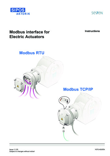
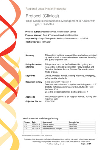
MODBUS Application Protocol Specification V1.1b1Modbus-IDAIntroduction1.1Scope of this documentMODBUS is an application layer messaging protocol, positioned at level 7 of the OSI model,that provides client/server communication between devices connected on different types ofbuses or networks.The industry’s serial de facto standard since 1979, MODBUS continues to enable millions ofautomation devices to communicate. Today, support for the simple and elegant structure ofMODBUS continues to grow. The Internet community can access MODBUS at a reservedsystem port 502 on the TCP/IP stack.MODBUS is a request/reply protocol and offers services specified by function codes.MODBUS function codes are elements of MODBUS request/reply PDUs. The objective of thisdocument is to describe the function codes used within the framework of MODBUStransactions.MODBUS is an application layer messaging protocol for client/server communication betweendevices connected on different types of buses or networks.It is currently implemented using:y TCP/IP over Ethernet. See MODBUS Messaging Implementation Guide V1.0a.y Asynchronous serial transmission over a variety of media (wire : EIA/TIA-232-E, EIA422, EIA/TIA-485-A; fiber, radio, etc.)yMODBUS PLUS, a high speed token passing network.MODBUS APPLICATION LAYERModbus on TCPTCPIPOtherMODBUS / HDLCMaster / SlaveEthernet II /802.3OtherPhysical layerEIA/TIA-232 orEIA/TIA-485EthernetPhysical layerFigure 1:MODBUS communication stackReferences1. RFC 791, Internet Protocol, Sep81 DARPA2AbbreviationsADUApplication Data UnitHDLC High level Data Link ControlHMIHuman Machine InterfaceIETFInternet Engineering Task ForceI/OInput/OutputDecember 28, 2006http://www.Modbus-IDA.org2/51
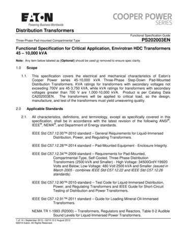
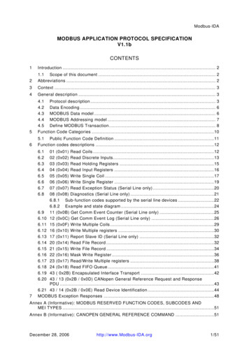
MODBUS Application Protocol Specification V1.1bIPInternet ProtocolMACMedium Access ControlMBMODBUS ProtocolModbus-IDAMBAP MODBUS Application ProtocolPDUProtocol Data UnitPLCProgrammable Logic ControllerTCPTransport Control Protocol3ContextThe MODBUS protocol allows an easy communication within all types of networkarchitectures.MODBUS COMMUNICATIONDrivePLCHMII/ OI/ OPLCI/ OMODBUS ON TCP/IPPLCHMIDeviceGatewayMODBUS ON RS485GatewayMODBUS ON RS232MODBUS ON MB GatewayPLCI/ OI/ ODriveI/ ODeviceI/ OFigure 2:Example of MODBUS Network ArchitectureEvery type of devices (PLC, HMI, Control Panel, Driver, Motion control, I/O Device ) can useMODBUS protocol to initiate a remote operation.The same communication can be done as well on serial line as on an Ethernet TCP/IPnetworks. Gateways allow a communication between several types of buses or network usingthe MODBUS protocol.44.1General descriptionProtocol descriptionThe MODBUS protocol defines a simple protocol data unit (PDU) independent of theunderlying communication layers. The mapping of MODBUS protocol on specific buses ornetwork can introduce some additional fields on the application data unit (ADU).December 28, 2006http://www.Modbus-IDA.org3/51
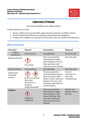
MODBUS Application Protocol Specification V1.1bModbus-IDAADUAdditional addressFunction codeDataError checkPDUFigure 3:General MODBUS frameThe MODBUS application data unit is built by the client that initiates a MODBUS transaction.The function indicates to the server what kind of action to perform. The MODBUS applicationprotocol establishes the format of a request initiated by a client.The function code field of a MODBUS data unit is coded in one byte. Valid codes are in therange of 1 . 255 decimal (the range 128 – 255 is reserved and used for exceptionresponses). When a message is sent from a Client to a Server device the function code fieldtells the server what kind of action to perform. Function code "0" is not valid.Sub-function codes are added to some function codes to define multiple actions.The data field of messages sent from a client to server devices contains additionalinformation that the server uses to take the action defined by the function code. This caninclude items like discrete and register addresses, the quantity of items to be handled, andthe count of actual data bytes in the field.The data field may be nonexistent (of zero length) in certain kinds of requests, in this casethe server does not require any additional information. The function code alone specifies theaction.If no error occurs related to the MODBUS function requested in a properly received MODBUSADU the data field of a response from a server to a client contains the data requested. If anerror related to the MODBUS function requested occurs, the field contains an exception codethat the server application can use to determine the next action to be taken.For example a client can read the ON / OFF states of a group of discrete outputs or inputs orit can read/write the data contents of a group of registers.When the server responds to the client, it uses the function code field to indicate either anormal (error-free) response or that some kind of error occurred (called an exceptionresponse). For a normal response, the server simply echoes to the request the originalfunction code.ClientServerInitiate requestFunction codeData RequestPerform the actionInitiate the responseFunction codeData ResponseReceive the responseFigure 4:MODBUS transaction (error free)For an exception response, the server returns a code that is equivalent to the originalfunction code from the request PDU with its most significant bit set to logic 1.December 28, 2006http://www.Modbus-IDA.org4/51
MODBUS Application Protocol Specification V1.1bClientModbus-IDAServerInitiate requestFunction codeData RequestError detected in the actionInitiate an errorException Function codeReceive the responseFigure 5:Exception codeMODBUS transaction (exception response))Note: It is desirable to manage a time out in order not to indefinitely wait for an answer which will perhapsnever arrive.The size of the MODBUS PDU is limited by the size constraint inherited from the firstMODBUS implementation on Serial Line network (max. RS485 ADU 256 bytes).Therefore:MODBUS PDU for serial line communication 256 - Server address (1 byte) - CRC (2bytes) 253 bytes.Consequently:RS232 / RS485 ADU 253 bytes Server address (1 byte) CRC (2 bytes) 256 bytes.TCP MODBUS ADU 253 bytes MBAP (7 bytes) 260 bytes.The MODBUS protocol defines three PDUs. They are : MODBUS Request PDU, mb req pdu MODBUS Response PDU, mb rsp pdu MODBUS Exception Response PDU, mb excep rsp pduThe mb req pdu is defined as:mb req pdu {function code, request data},wherefunction code [1 byte] MODBUS function code,request data [n bytes] This field is function code dependent and usuallycontains information such as variable references,variable counts, data offsets, sub-function codes etc.The mb rsp pdu is defined as:mb rsp pdu {function code, response data},wherefunction code [1 byte] MODBUS function coderesponse data [n bytes] This field is function code dependent and usuallycontains information such as variable references,variable counts, data offsets, sub-function codes, etc.December 28, 2006http://www.Modbus-IDA.org5/51
MODBUS Application Protocol Specification V1.1bModbus-IDAThe mb excep rsp pdu is defined as:mb excep rsp pdu {exception-function code, request data},whereexception-function code [1 byte] MODBUS function code 0x80exception code [1 byte] MODBUS Exception Code Defined in table"MODBUS Exception Codes" (see section 7 ).4.2 Data EncodingMODBUS uses a ‘big-Endian’ representation for addresses and data items. This meansthat when a numerical quantity larger than a single byte is transmitted, the mostsignificant byte is sent first. So for exampleRegister size16 - bits)4.3value0x1234the first byte sent is0x12then 0x34Note: For more details, see [1] .MODBUS Data modelMODBUS bases its data model on a series of tables that have distinguishing characteristics.The four primary tables are:Primary tablesObject typeType ofDiscretes InputSingle bitRead-OnlyCoilsSingle bitRead-WriteInput Registers16-bit wordRead-OnlyHolding Registers16-bit wordRead-WriteCommentsThis type of data can be provided by an I/O system.This type of data can be alterable by an applicationprogram.This type of data can be provided by an I/O systemThis type of data can be alterable by an applicationprogram.The distinctions between inputs and outputs, and between bit-addressable and wordaddressable data items, do not imply any application behavior. It is perfectly acceptable, andvery common, to regard all four tables as overlaying one another, if this is the most naturalinterpretation on the target machine in question.For each of the primary tables, the protocol allows individual selection of 65536 data items,and the operations of read or write of those items are designed to span multiple consecutivedata items up to a data size limit which is dependent on the transaction function code.It’s obvious that all the data handled via MODBUS (bits, registers) must be located in deviceapplication memory. But physical address in memory should not be confused with datareference. The only requirement is to link data reference with physical address.MODBUS logical reference numbers, which are used in MODBUS functions, are unsignedinteger indices starting at zero. Implementation examples of MODBUS modelThe examples below show two ways of organizing the data in device. There are differentorganizations pos
The MODBUS application data unit is built by the client that initiates a MODBUS transaction. The function indicates to the server what kind of action to perform. The MODBUS application protocol establishes the format of a request initiated by a client. The function code field of a MODBUS data unit is coded in one byte. Valid codes are in the