Transcription
AN-023Protege Controller ModBUS Slaveand Register MapApplication Note
The specifications and descriptions of products and services contained in this document were correct at the timeof printing. Integrated Control Technology Limited reserves the right to change specifications or withdrawproducts without notice. No part of this document may be reproduced, photocopied, or transmitted in any formor by any means (electronic or mechanical), for any purpose, without the express written permission of IntegratedControl Technology Limited. Designed and manufactured by Integrated Control Technology Limited. Protege and the Protege Logo are registered trademarks of Integrated Control Technology Limited. All other brand orproduct names are trademarks or registered trademarks of their respective holders.Copyright Integrated Control Technology Limited 2003-2011. All rights reserved.Publication Date: October 20112AN-023 Protege Controller ModBUS Slave and Register Map Application Note October 2011
ContentsProtege System 5Application Note Information .5About ModBUS 6ModBUS Register Maps .6Register Reference Description .6Service Configuration 7Programming The Service .7LCD Keypad Programming .7Starting The Service.9Protege System Management Suite Programming .9Register Configuration 11Map Structure .11Physical PGM Outputs Coil Address Map .11System Controller PGM Output Coils .11LCD Keypad PGM Output Coils .1216 Zone Input Expander PGM Output Coils .13Two Reader Expander (All Models) PGM Output Coils .1416 PGM Output Expander PGM Output Coils .15Analog Input/Output Expander PGM Output Coils .16System Doors Output Coils .16System Automation Control Output Coils .17Zone Coil Translation Functions .17Control Panel Zone Coil Translation Functions .17LCD Keypad Zone Coil Translation Functions .18Zone Expander Zone Coil Translation Functions.18Two Reader Expander Zone Coil Translation Functions .19Input Address Map .19System Controller Zone Input Address.20LCD Keypad Zone Inputs .2016 Zone Input Expander Zone Inputs .21Two Reader Expander Zone Inputs .2216 PGM Output Expander Zone Inputs .224 Channel Analog Input/Output Expander Zone Inputs.22System Controller Trouble Zone Input Address .23LCD Keypad Trouble Zone Input .24AN-023 Protege Controller ModBUS Slave and Register Map Application Note October 20113
Zone Expander Trouble Zone Input .25Two Reader Expander Trouble Zone Input .2616 PGM Output Expander Trouble Zone Input .274 Channel Analog Input/Output Expander Trouble Zone Input .27Input Register Address Map .28System Controller Analog Inputs .28System Controller Information .29Schedule Status .29Register Address Map .30Area Status Register Map .31Area Extended Status Register Map.32Area User Current Count Register Map .32Door Status Register Map .33PGM Outputs Register Map .34Variable Values Register Map .34Remote ModBUS Register Map .34References 35ModBUS References .35Source Code For ModBUS Drivers.35Contact 364AN-023 Protege Controller ModBUS Slave and Register Map Application Note October 2011
Protege SystemThe ICT Protege System is a powerful integrated alarm and access control management system designed toprovide integration with building automation, apartment complex control and HVAC in one flexible package.Communication is over a proprietary high speed protocol across an encrypted local area network and AESEncrypted Proprietary RS-485 module network. Using modular-based hardware design, system installers havethe flexibility to accommodate any installation from small to large, residential or commercial.Application Note InformationThis Application Note describes the interface of the Protege System Controller to a ModBUS RTU Slave Networkand the register map associated with the ModBUS RTU Slave communication service.Application notes are provided as is without any implied warranty or intended use and are written by IntegratedControl Technology as an aid in programming and connecting devices to the Protege System.AN-023 Protege Controller ModBUS Slave and Register Map Application Note October 20115
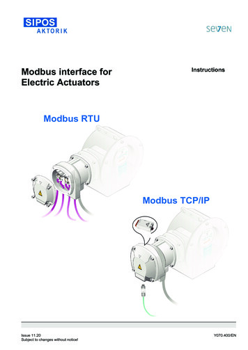
About ModBUSThe following information describes the operation of Modbus as it relates to the Protege System Controller. Formore detailed information on Modbus, you may also refer to the Modicon ModBUS Reference Guide,PI-MBUS-300 Rev J, available via download from www.public.modicon.com.The ModBUS protocol provides an industry standard method that ModBUS devices use for parsing messages.This protocol was developed by Modicon, Incorporated, for industrial automation systems and Modiconprogrammable controllers. ModBUS devices communicate using a master-slave technique in which only onedevice (the master) can initiate transactions (called queries). The other devices (slaves) respond by supplying therequested data to the master, or by taking the action requested in the query. A slave is any peripheral device (I/Otransducer, valve, network drive, or other measuring device) which processes information and sends its output tothe master using ModBUS. The Protege System Controller operates as a slave device, while a typical masterdevice is a host computer running appropriate application software.Masters can address individual slaves, or can initiate a broadcast message to all slaves. Slaves return a responseto all queries addressed to them individually, but do not respond to broadcast queries. A master’s query consistsof a slave address (or broadcast address), a function code defining the requested action, any required data, andan error checking field. A slave’s response consists of fields confirming the action taken, any data to be returned,and an error checking field. Note that the query and response both include a device address, plus a functioncode, plus applicable data, and an error checking field. If no error occurs, the slave’s response contains the datarequested. If an error occurs in the query received, or if the slave is unable to perform the action requested, theslave will return an exception message as its response (see ModBUS Exceptions on the modbus.org website).The error check field of the message frame allows the master to confirm that the contents of the message arevalid. Additionally, parity checking is also applied to each transmitted character in its data frame.ModBUS Register MapsModBUS devices usually include a Register Map. ModBUS functions operate on register map registers tomonitor, configure, and control module I/O. A register map is provided in this document for the Protege SystemController. You will also find it helpful to refer to the register map as you review the functionality that is required tobe integrated with the Protege System Controller.ModBUS registers are organized into reference types identified by the leading number of the reference address:Register Reference Description0xxxxx Read/Write Discrete Outputs or Coils. A 0x reference address is used to drive output data to a digitaloutput channel.1xxxxx Read Discrete Inputs. The ON/OFF status of a 1x reference address is controlled by the correspondingdigital input channel.3xxxxx Read Input Registers. A 3x reference register contains a 16-bit number received from an externalsource—e.g. an analog input signal.4xxxxx Read/Write Output or Holding Registers. A 4x register is used to store 16-bits of numerical data (binary ordecimal), or to send the data from the CPU to an analog output channel.Not all ModBUS functions operate on register map registers. For example, the Report Slave ID and Reset Slavefunctions do not operate on register map locations.Standard ModBUS networks employ one of two types of transmission modes. ASCII Mode, or RTU Mode. Thetransmission mode defines the bit contents of the message bytes transmitted along the network, and how themessage information is to be packed into the message stream and decoded.The mode of transmission is selected within the Protege ModBUS Slave Service along with other serial portcommunication parameters (address, baud rate, parity, etc.) as part of the service configuration. The ModBUSRTU Slave Service in the Protege System Controller supports the Binary Mode only and ASCII mode is notsupported due to the increased processing time required.6AN-023 Protege Controller ModBUS Slave and Register Map Application Note October 2011
Service ConfigurationThe following steps show how to configure the service. If you are connecting to a live ModBUS Network ensurethat your Slave ID and related information is accurate and that you have tested the connection with a test suite orother application first.iUse a test suite or application such as TopServer to communicate with your ModBUS Service prior todeployment in to a live network. This will allow verification of the points and registers.Programming The ServiceTo program the service ensure that you have the Slave ID and Communication Parameters from the hostapplication. In the example below we have a slave ID of 01 and default parameters of 9600 baud and even parity.LCD Keypad ProgrammingIf you are not sure about navigation within the Protege LCD Keypad review the installation and reference manual.The default insta
Application Note Information This Application Note describes the interface of the Pr otege System Controller to a ModBUS RTU Slave Network and the register map associated with the ModBUS RTU Slave communication service. Application notes are provided as is without any implied warranty or intended use and are written by Integrated
